



Abstract
This article explores the acoustic characteristics and the relevant flow features of jets impinging on permeable plates. Noise generated due to the interaction of the jet with permeable plates is compared with jets impinging on an impermeable plate and the corresponding free jet. This study systematically measures various parameters, including pore size, porosity, and pressure drop, to precisely quantify the permeability of the plates using the Forchheimer equation. The focus is on investigating the impact of permeability on noise reduction. An acoustic study is performed by carrying out blow-up and blow-down tests to find the effect of permeability at different nozzle pressure ratios and different nozzle-plate spacings. An extensive directivity study is conducted to find the directionality of acoustic emissions and calculate acoustic power. It is found that the overall sound pressure level is lower for the jets impinging on the permeable plates compared to the impermeable plates in subsonic cases. It is also observed that the insertion of the permeable plates in supersonic jets generates less noise compared to the corresponding free jet. It is found that most of the tones are absent in the case of permeable plates for supersonic jets, whereas the tones are present with lesser amplitude compared to jets impinging on impermeable plates for subsonic and transonic jets. Finally, flow measurement and flow visualization studies are carried out to understand the flow physics responsible for the noise variance. This study illuminates that the passage of flow through the porous plate results in the reduction of wall-jet velocities, thereby suppressing the turbulent mixing noise. The absence of shock oscillations in front of the permeable plate is identified as the cause of the mitigation of impinging tones.
Introduction and state of the art
High-speed impinging jets display interesting flow and acoustic features and are employed in various propulsion and heat transfer applications. Examples include turbine blades, laser systems, medical equipment, fusion blankets, electronic chips, etc. Thus, they span across a multitude of physical, hydrodynamic, and acoustic scales. The high rate of heat, mass, and momentum exchange makes these flows very attractive in many applications. As a consequence of flow, they also contain other features responsible for noise emission, resulting in broadband noise, turbulent mixing noise, and Mach wave radiation at high speeds. In addition to this, there are instabilities, which are responsible for the production of very painful discrete tones caused by the interaction of vortical structures with the shock-cells and impingement plate. Noise is generally an undesirable consequence causing health concerns 1 or structural fatigue damage. 2
The impingement flow scenario comprises the free jet, the impingement region, and the wall jet region. The factors that influence an impingement system are the nozzle pressure ratio (NPR) of the issuing jet, initial conditions of the flow, jet-to-plate spacing, plate dimensions, plate characteristics, etc. A brief review of the literature on impinging jet noise is presented by the authors elsewhere, Dhamanekar and Srinivasan. 3 The detailed work of impinging jet noise can be found in review articles.4,5 Some important effects of the nozzle plate spacing, nozzle pressure ratio, and impingement surfaces on impingement noise are discussed below.
Marsh 6 experimented with a 1.5-inch diameter subsonic air jet with 0.66 exit Mach number impinging perpendicularly on a large, flat, rigid plate. He found that the wall jet part of the impinging jet causes a considerable increase in broadband noise and observed a steady and intense tone when the nozzle-plate spacing is twice the diameter of the nozzle. He observed that the spectrum of noise is modified as the nozzle-plate spacing increases; the amplitude and frequency of the dominant tone decrease and the sharp peak transforms into a broadband-like hump. Experiments by Smith and Powell 7 showed that such a resonant effect enhances the sound intensity with an increase in the plate size. The stand-off shock wave becomes unstable when it is in a pressure recovery region of the free jet.
Golubkov et al 8 observed strong acoustic emissions when central compression shock interacts with a small plate in the jet path. When the jet impinges on a large plate, Semiletenko et al. 9 found oscillations of the shock waves ceased when there is enough nozzle-plate spacing to accommodate a second compression shock ahead of the plate.
Wagner 10 argued that a feedback mechanism existed, wherein the sound produced by the impingement of vortices on the plate traveled upstream through the jet core, causing disturbances in the shear layer. Neuwerth 11 found eight phases of feedback loops and concluded that round jets can produce both symmetric and asymmetric modes. Olsen et al. 12 reported that the phenomenon existed at the nozzle-plate spacing of 4.7 and 7.05 diameters, but it was much less intense, while Preisser and Block 13 did not report any tones for five to 10 diameters nozzle-plate spacing. The Reynolds number for these situations was relatively large, about half a million, although Wagner's was the smallest. Thus, other factors besides the Reynolds number must have a strong influence on the degree of instability. Pieris et. al. 14 studied the vortex dynamics of impinging high aspect ratio planar jet and showed the effects of Reynolds number and impingement height on the vortex evolution. Schloth 15 indicated that the flow-field of the impinging jet is characterized mainly by a strong rise in static pressure in the impingement region near the surface and by the boundary layer development in the wall jet region. Ho and Nosseir 16 found that the noise measured perpendicular to the jet axis is produced by two different physical phenomena. One is the impact of the large coherent structures on the plate and the other is concerned with the initial shear layer instability. The noise generated by the impingement of the coherent structures on the plate is dominant compared to other sources. Krothapalli 17 showed impinging tones appear to originate from the impingement region, whereas, choked jet tones emerge from around the end of the third shock cell.
Levin and Wardwell 18 showed that even though the flow structures of an ideally-expanded supersonic jet and an under-expanded impinging jet significantly differ, both can produce discrete impinging tones depending on operating conditions. Henderson et al. 19 observed the production of impinging tones when a Mach disk occurs in the flow and cessation when the first or second shock waves attain a conical shape. Further, they supported the hypothesis that the axial motion of the stand-off shock produced a pulsatile wall jet, resulting in the production of tones.
Kumar et al.
20
observed that the shear layer is dominated by a helical mode of instabilities for
There are several efficient possibilities to disrupt the feedback loop, such as shear layer alteration (shear layer thickening, shear layer excitation, etc.,) or obstructing the upstream propagating acoustic waves [Alvi et al.]. 27 Based on these concepts, many attempts were made to suppress the feedback mechanism. For instance, Petrie 28 mitigated impinging tones by using three methods. First, by introducing disturbances into the shear layer at the jet exit to modify the initial disturbance responsible for instability; Second, by changing the plate geometry to alter the acoustic wave strength/frequency responsible for the feedback loop; Third, by inserting disturbances at the stagnation region. Elavarasan et al. 29 destroyed the feedback loop by inserting a baffle plate near the nozzle exit in the outside ambient flow region. Kastner and Samimy 30 used Hartmann tube fluidic actuators and steady injection; Sarpotdar et al. 31 employed Powered Resonance Tube (PRT) actuators whereas, Alvi and group27,32 applied microjets to control the noise. Fluidic inserts are applied to reduce the noise produced by jets impinging on aircraft carrier deck. 33 Sankaran et al. 34 examined the reduction in the sound pressure level (SPL) by water injection and found that the water injection does not significantly affect the low-frequency mixing noise, but it suppresses the mid-frequency broadband shock-associated noise and appreciably influences the high-frequency fine-scale mixing. Salehian and Mankbadi 35 showed that water injection from the ground plane reduces the far-field sound by about 2–3 dB at low frequencies (up to 4 kHz). Dhamanekar and Srinivasan 36 studied the flow and acoustic variation due to the jet impinging on inclined plates and found the reduction or enhancement of the acoustic radiation depends on the noise location measurement, standoff distance, and nozzle pressure ratio. Whereas, Qi et. al. 37 showed the jet impinging on inclined grooved surfaces produces less noise compared to smooth inclined surfaces. Dhamanekar and Srinivasan's findings revealed that the central protrusion on the impinging plate exhibits greater efficacy in attenuating tones within supersonic impinging jets compared to those present in subsonic impinging jets. 38 Recently, Lubert et al. 39 conducted a comprehensive review of the research conducted by NASA over the past 50 years on the physics underlying the generation and mitigation of noise from launch vehicles. Different noise reduction techniques for impinging jets can be found in the review articles of Jiang et al., 5 and Salehian and Mankbadi. 40
Thus, from a review of the literature on jet impingement noise reveals that studies on the effect of a porous plate are scarce. However, one can find the use of a porous coating to reduce aerodynamic drag and noise of circular cylinders, 41 especially vortex shedding noise 42 or trailing edge noise. 43 Recently, Karthikeyan and Venkatakrishnan 44 observed that replacing the solid launch platform with a perforated one leads to lower noise levels than the solid one but still higher than the case where the launch platform is absent. Wiley and Kumar 45 studied the impingement of a supersonic under-expanded jet on plates of different permeability/perforations. They found that the acoustic intensity can be reduced by making the obstacle permeable. The impinging surface used in the present work is quite different from the perforated plates used by other researchers.44,45 That is, in most cases isotropic porous media is used whereas, in the present work, an anisotropic porous media is used. Further, their measurement is limited to near-field at one or two points. This was the motivation for the present work wherein detailed investigations of noise production from jets impinging on different permeable plates are carried out. It may be noted that the words ‘permeable’ and ‘porous’ have been used interchangeably in this article. The paper outline is as follows: First the experimental setup and uncertainties in the measurements is discussed. In the next section, impingement plate characteristics are specified using various techniques. Subsequent sections are dedicated to comprehensive discussions of the acoustic results obtained during both blow-up and blow-down tests, as well as an in-depth investigation of directivity. Further, an attempt is made to support the acoustic data using flow measurement and flow visualization. Finally, the article concludes with a concise summary of the key findings and insights presented in the work. Before, discussing the experimental setup, procedures, and results, noise sources and generation mechanism is briefly described in the next subsection.
Noise sources in free and impinging jet
Depending upon the flow conditions, free or impinging jets produce various types of noise such as turbulent mixing noise, shock-associated noise, screech, and impinging tones. The profound intricacies of noise generation in both free and impinging jets are meticulously elucidated in the illustrious review article authored by Edgington-Mitchell. 4
Turbulent mixing noise
Turbulent mixing noise is generated due to the interaction between the flow structures in the shear layer of the jet/wall-jet with the surrounding ambient air. Turbulent mixing noise is caused by the large and small-scale turbulent structures in the jet mixing layers. The noise produced by large-scale structures is dominant over small-scale structures. The turbulent mixing noise of jets consists of high and low-frequency noise, regardless of the jet exit condition. The spectrum of turbulent mixing noise is generally broadband. High-frequency noise is produced by the fine-scale turbulence near the nozzle exit due to the instabilities in the shear layer and the low-frequency noise is generated by the large turbulence structure away from the nozzle exit. High-frequency noise is dominant in the sideline and upstream directions. The directivity of turbulent mixing noise is highly affected by the convection of noise sources and the refraction of noise due to the jet flow velocity. 46 These effects depend on the jet and ambient conditions. In the case of an impinging jet, in addition to the free jet, the wall jet produced by the flow deflection is responsible for turbulent mixing noise. Turbulent mixing noise produced by wall-jet consists of both free shear layer and boundary layer noise. This enhances the noise of the impinging jet by 10–15 dB more than the corresponding free jet configuration.
Shock-associated noise
Subsonic and perfectly expanded supersonic jets emit noise, only due to the turbulent mixing process. Imperfectly expanded jets contain shock cell structures in the flow due to the mismatch of pressure and flow direction. The interaction between these quasiperiodic shock cells and the downstream propagating large-scale structures in the shear layer generates shock-associated noise. Shock-associated noise can be divided into broadband shock-associated noise (BBSAN) and discrete frequency or screech noise.
Broadband shock-associated noise
The distinct features of the broadband shock-associated noise are the peak frequency and the spectral bandwidth of it increases in the upstream direction. The amplitude and frequency of peak Broadband shock-associated noise (BBSAN) increases and decreases, respectively, with temperature for over-expanded jets. Whereas, for under-expanded jets exact opposite take place. Tam
47
showed using a stochastic model that, the BBSAN intensity scales with the shock strength and the peak Strouhal number of BBSAN depends on the fully expanded jet Mach number M
j
and the observation angle. The intensity of BBSAN is directly proportional to
Screech
Screech is the most pronounced word in aeroacoustics. This is a very strong discrete tone present in the spectrum of incorrectly expanded jets at certain conditions. Screech is clearly visible as a distinct tone and its frequency falls close to the BBSAN. Powell
48
proposed that a feedback loop is responsible for the generation of a screech tone. The well-known feedback can be explained as follows, “The coherent vortical structures developing at the shear layers are convected downstream and interact with the oscillating shock cells producing strong acoustic waves. The interaction between upstream propagating acoustic waves with the nozzle lip and the thin shear layer stimulates new instability waves which travel downstream, thus closing the feedback loop”. Screech exhibits different oscillation modes such as axisymmetric, helical, and flapping. There is a lot of work has been done to understand the noise generation mechanism and their frequency prediction, and finally, various methods were employed to reduce this noise. Gao and Li
49
found the multimode screech frequency formula as,


The properties such as intensities, frequencies and oscillation modes of screech tones depend on the Mach number, temperature, the nozzle lip thickness and initial conditions of jet, as well as ambient atmospheric conditions and the presence of sound reflecting surfaces in the immediate environment of the jet. The free jet experimental setup is validated using screech formula, the details are discussed in Dhamanekar and Srinivasan. 3
Impinging tones
This special type of noise occurs when any obstacle is placed at a particular position in the jet path. These tones occur both in subsonic and supersonic impinging jets and they differ from the screech by their generation mechanism. In the case of a subsonic impinging jet these tones occur due to the feedback loop, whereas in the case of a supersonic impinging jet, either feedback loop or random shock oscillation is responsible for impinging tones. The feedback loop in the case of impinging jet can be explained as, “vortical instabilities in the shear layer at the nozzle exit are formed between the jet and ambient air. These instabilities are amplified as they convect downstream. When these instabilities encounter the obstacle, normal to the jet axis, they produce strong pressure fluctuations that propagate upstream as acoustic waves along the jet column or outside it. When these acoustic waves reach the nozzle exit, they further excite the shear-layer disturbances resulting in the shedding of new vortices. The vortical instabilities and acoustic waves form the feedback loop”. Depending on the obstacle shape various tones can be produced, such as plate, edge, hole, or ring tones. Impinging tonal frequency shows staging phenomenon
50
for flat smooth plate and is given by equation (3).

Experimental setup and uncertainties
Test facility
The test facility consists of the air supply system and jet facility in an anechoic environment. The air is compressed using an air compressor and stored in the two reservoirs with a total capacity of 20 m3. The compressor and reservoirs are located outside the laboratory so that their noise is isolated from the jet facility. The compressor can pressurise the reservoir up to a 7.5 bar gauge. The 4-inch pipe is used to supply the compressed air from the reservoir to the settling chamber. The air is dried using moisture remover and purified using a filter, before the settling chamber. A pressure-regulating valve is used to regulate the pressure inside the settling chamber. The experiments are carried out in an anechoic chamber of size 2.5 m × 2 m × 2 m (wedge tip-to-tip) as shown in Figure 1. Impinging jet facility inside the anechoic chamber.
Square pyramidal polyurethane foam wedges are glued to all inner surfaces of the chamber. The cut-off frequency of the chamber is 700 Hz, determined using inverse square law. The chamber has two windows to permit the entrainment of air and its exit. The cold free-jet test facility consists of a settling chamber fixed inside the anechoic chamber and has dimensions of 380 mm internal diameter and 700 mm length. The settling chamber is converged from 380 mm to 43.5 mm over a length of 100 mm, wherein, the required orifices are mounted using a disk holder.
Flow disturbances are mitigated by flow conditioning meshes of progressive fineness and the structure-borne acoustic disturbances are lowered by coating the inner wall of the settling chamber with polyurethane foam. In front of the jet facility, a linear traverse is fixed on which the plates of the required size can be mounted. The traverse can be used for varying the spacing between the jet exit and the plate. To reduce the reflections of acoustic radiation, metallic surfaces such as the settling chamber, disk-holder, traverse, etc. are covered with acoustic foam.
Instrumentation
The acoustic data is acquired using ¼-inch microphones (B&K 4939 and PCB 377A01). The sensitivity of the microphones used is 4 mV/Pa, and both microphones possess a flat frequency response in the range of 4 Hz–70 kHz within ±1 dB. The microphone signal is acquired at a sampling rate of 150000 samples/sec. Aliasing errors in the microphone signals are eliminated by passing the signal through a low-pass analog filter (Krohn-Hite, Model-3364) at 70 kHz. A National Instruments data acquisition board (NI-PCI-6143) is used for acquiring the microphone data. A piezo-resistive pressure transducer (Endevco Model 8510C-100) is used for continuous pressure measurement inside the settling chamber during blow-up and blow-down studies. An angular traverse is used to study the directivity pattern. The microphone survey is carried out along a circular path with the jet exit as the centre, and the microphone always facing the centre. The circular path spans from the downstream to the upstream angles, in the range of 35° to 135° with an increment of 5° using angular stepper motor traverse controlled by a LabVIEW program. A thermocouple is used to measure the temperature inside the settling chamber. Flow velocity measurements are made using a 1 mm outer diameter pitot tube connected to MARTEL digital manometer T-140
Uncertainty analysis
The microphones are calibrated using a B&K pistonphone type 4228 calibrator (single point calibration at 250 Hz and 124 dB). The piezo-resistive transducer employed for pressure measurement during blowdown has an uncertainty of ±0.2% of full scale. The anechoic room environment (28°C and relative humidity, 80%) is nearly constant with a maximum temperature variation of ±1°C and ±2% variation in relative humidity for each trial of the experiment. The sound pressure level reported here is relative to the reference pressure of 20 µPa. The frequency resolution based on the FFT (Fast Fourier Transform) size is 37 Hz over the range of frequency from 700 Hz to 70 kHz. The overall measurement error in acoustic data (OASPL - OverAll Sound Pressure Level (dB reference 20 μPa)) including repeatability errors is within ±1.0 dB. The microphone positioning error is within ±1.0 mm and the microphone angle is within ±1°. The error in the nozzle-plate spacing is ±0.2 mm and the uncertainty in pitot velocity measurement is 2%. The validation of free-jet and impinging jet results are described in detail in Dhamanekar and Srinivasan 3 and therefore not repeated here.
Permeable (Porous) plate specifications
In the present work, three plates of the dimension 200×200×22 mm and another plate of the dimension 200×200×50 mm made up of ceramics are used. These ceramic porous plates are made from SiC-Al2O3 powders using polymeric foams as a mould of uniform pores. Porous plates consist of several interconnected openings called pores. This structure provides less flow resistance compared to impermeable plates. Three different parameters are used to define the characteristics of porous plates, i.e., the number of pores, porosity, and pressure drop. First, generally, the manufacturer specifies porous plates using PPI (pores per inch) unit, counting the number of pores per unit length. In the present work 10, 20, and 30 PPI are used. Second, these plates can be specified using porosity. Porosity can be defined as the ratio of void volume in the specimen to the total volume of the specimen. To measure the porosity commonly water displacement or air volume methods are used. This work uses the water displacement/water immersion method to find the porosity of all the plates. The porosity of all the plates is nearly 75%. Finally, an important specification of such plates in flow problems is the pressure drop. The pressure drop is measured for all the porous plates under various conditions. It is found that the pressure drop per unit length increases as the pores per inch increase for all inlet velocities. Further, the pressure drop increases with an increase in inlet velocity as shown in Figure 2. Forchheimer
51
described the pressure drop using velocity as follows, Pressure drop across various plates at various inlet velocities. Specification of porous plates used in the experiments. (a) Porous plate with holding arrangement (b) Arrangements of microphones during blow-up and blow-down process.



Blow-up and blow-down tests
Blow-up and blow-down tests are performed to find the effects of permeability with respect to NPR. A jet from a 10 mm diameter (d) orifice and three plates of almost equal porosity with different permeability and pore sizes are used. The plates of pore sizes 10, 20, and 30 PPI with 200×200 mm cross-section and 22 mm thickness are used. This study is carried out for three nozzle plate spacings, h/d = 3.0, 4.0, and 5.0. During these tests, both the near-field and the far-field data are collected. Three near-field microphones placed at R/d = 15 from the jet exit and normal to each other showed that the acoustic propagation is almost axisymmetric, as shown in Figure 4. Similarly, both the near-field and the far-field microphones showed no hysteresis effect during blow-up and blow-down (Figure 5) as observed in the impermeable impinging jet [Dhamanekar and Srinivasan].
3
Further, the trends observed in near and far-field are the same. Microphones 2, 3, and 4 show almost similar trends, whereas Microphone 1 shows a similar trend with some lesser amplitude compared to others as it is far away from the jet. Comparison of microphones placed at different locations during blow-down tests for 30 PPI at h/d = 5.0. Comparison of blow-up and blow-down study for various h/d, using a microphone placed at R/d = 15 and θ = 90o (a) 30 PPI (b) 20 PPI (c) 10 PPI.

Figures 5 and 6 show that OASPL increases as NPR increases in the subsonic region irrespective of stand-off distance for all porous plates. The OASPL values shoot up and decrease in the initial supersonic region (NPR ∼ 2) like impinging jets on impermeable plate.
3
Then the OASPL shows an increasing trend with increasing reservoir pressure up to NPR∼ 2.7. A sharp increase in OASPL is observed at h/d = 3.0, 4.0 and 5.0 for 30 PPI, whereas at h/d = 4.0 and 5.0 for 20 PPI. However, for 10 PPI this increase in OASPL is observed at NPR∼2.9 for h/d = 5.0 only. For 30 PPI, OASPL decreases for NPR = 2.9, 3.2, and 3.3 at h/d = 3.0, 4.0, and 5.0, respectively. For 20 PPI, OASPL decreases for NPR = 3.2 and 3.3 at h/d = 4.0 and 5.0 respectively, whereas, for 10 PPI it decreases for NPR = 3.1 at h/d = 5.0. With a further increase in NPR, OASPL gradually increases for all cases. This trend is observed in both near-field microphones (Figure 5) and far-field microphones (Figure 6). Further, it is observed that in subsonic impinging jets, OASPL shows non-monotonic behavior with respect to h/d. This is mainly due to the different levels of damping of shear layer/vortices impact and hence the acoustic feedback loop. However, in the case of supersonic impinging jets, the OASPL increases with an increase in h/d for all porous plates which is contradictory to the impermeable impinging jet case. The phenomena happening at very close stand-off distances such as h/d ≤ 2.0 are discussed later, in the section on directivity studies. The next subsection deals with spectral analysis to identify the contributing modes to OASPL. The subsection also deals with toneless spectra calculations. Comparison of blow-up and blow-down study for various h/d, using a microphone placed at R/d = 40 and θ = 90o (a) 30 PPI (b) 20 PPI (c) 10 PPI.
Spectral analysis
The blow-up and blow-down test spectra of noise from jets impinging on permeable and impermeable plates revealed that most of the supersonic impinging tones are absent in the case of permeable plates for all h/d cases. However, there are few tones are observed for 2.75 < NPR < 3.25 with a frequency equal to screech frequency. Figures 7 and 8 clearly show that subsonic and transonic tones are still present for permeable plates at h/d = 4.0 and 5.0. Figures 7(a) and 8(a) show that the spectra of the impermeable plate at h/d = 4.0 and 5.0 respectively, are both rich in turbulent mixing noise and broadband shock-associated noise. Whereas Figure 7(b)–(d) shows a reduction in both turbulent mixing noise and broadband shock-associated noise apart from attenuation of tones at h/d = 4.0 for permeable plates. Similarly, Figure 8(b)–(d) shows a reduction in noise at h/d = 5.0 for permeable plates. However, a comparison of Figures 7 and 8 reveal that an increase in spacing results in an increase in both turbulent mixing and broadband shock-associated noise for permeable plates. The jumps observed in Figures 5 and 6 are due to the tones in the corresponding spectra (Figures 7 and 8). However, in the case of supersonic impinging jets, it is difficult to conclude whether the tones are caused by impingement feedback or screech feedback. The difficulty is because these tones are absent at higher NPR and small nozzle-plate spacing. Comparison of spectra for h/d = 4.0 using a microphone placed at R/d = 40 and θ = 90o (a) Impermeable (i) (b) 30 PPI (c) 20 PPI (d) 10 PPI. Comparison of spectra for h/d = 5.0 using a microphone placed at R/d = 40 and θ = 90o (a) Impermeable (i) (b) 30 PPI (c) 20 PPI (d) 10 PPI.

Toneless OASPL comparison
Tones in the spectra are removed for all the cases as discussed in Dhamanekar and Srinivasan.
3
Figure 9 Comparison of toneless OASPL at R/d = 15 and θ = 90o, for free jet and jet impinging on various permeability plates during the blow-down process at h/d (a) 3.0,(b) 4.0, and (c) 5.0.
Directivity study
In this section, first, the effects of nozzle plate spacing and nozzle pressure ratio for plates with different permeability are discussed. Second, the effect of plate permeability on noise at various angles is demonstrated in some cases. Third, spectral analysis is carried out to demonstrate the directory of various frequencies. Finally, the acoustic power of the jet impinging on various permeable plates is compared.
Effect of nozzle-plate spacing and NPR
The directivity study is performed as discussed in Dhamanekar and Srinivasan.
3
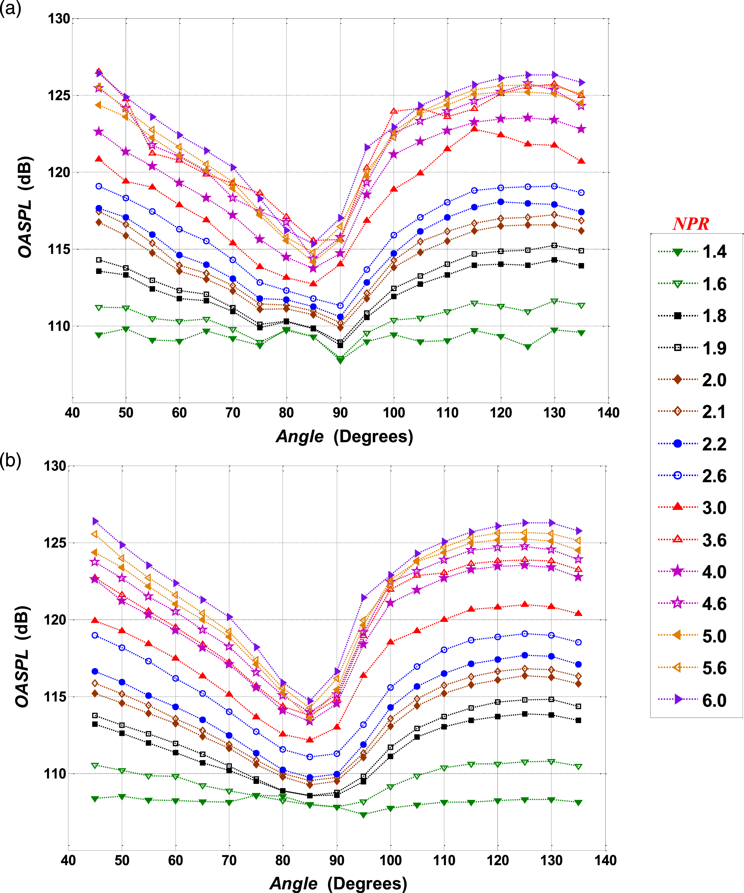
It is carried out for 9 nozzle plate spacings varying from h/d = 0.5 to 3.0 with an interval of 0.5d and from h/d = 4.0 to 6.0 with an interval of d and NPR is varied from 1.4 to 6.0 with an interval of 0.2. In this article, only h/d = 1.0 and 6.0 are discussed. Figures 10(a) and 11(a) show the effect of NPR at h/d = 1.0 and 6.0, respectively for the impermeable plate. Tones are either weak or absent in the case of h/d = 1.0. However, after the removal of these weak tones for h/d = 1.0, the OASPL varies linearly with NPR, and the directivity pattern is similar for all NPR, as shown in Figure 10(b) Effect of NPR on directivity pattern at R/d = 40, for jet impinging on an impermeable plate placed at h/d = 1.0 (a) with tone (b) without tone. Effect of NPR on directivity pattern at R/d = 40, for jet impinging on an impermeable plate placed at h/d = 6.0 (a) with tone (b) without tone.

Similar experiments are conducted for plates of different permeability values. It is found that the OASPL values on both sides of the plate are comparable, unlike the impermeable plate, due to the air passage through the pores. Figures 12 and 13 show the directivity pattern variation with NPR for 20 PPI plate at h/d = 1.0 and 6.0, respectively. It is observed that the OASPL decreases in front of the plate and increases behind the plate when compared to the impermeable plate. When the plate is close to the jet exit, the OASPL value is higher downstream of the plate compared to upstream, as shown in Figure 12. Further, it is found that for larger nozzle-plate spacing, the OASPL upstream of the plate increases as shown in Figure 13. Similar results are observed for 10 and 30 PPI permeable plates. Like the impermeable plate, some non-linearity in OASPL is observed with NPR for permeable plates, due to the presence of tones. Figures 12(b) and 13(b) show a linear variation of toneless OASPL with NPR. Effect of NPR on directivity pattern at R/d = 40, for jet impinging on the permeable plate (20 PPI) placed at h/d = 1.0 (a) with tone (b) without tone. Effect of NPR on directivity pattern at R/d = 40, for jet impinging on the permeable plate (20 PPI) placed at h/d = 6.0 (a) with tone (b) without tone.
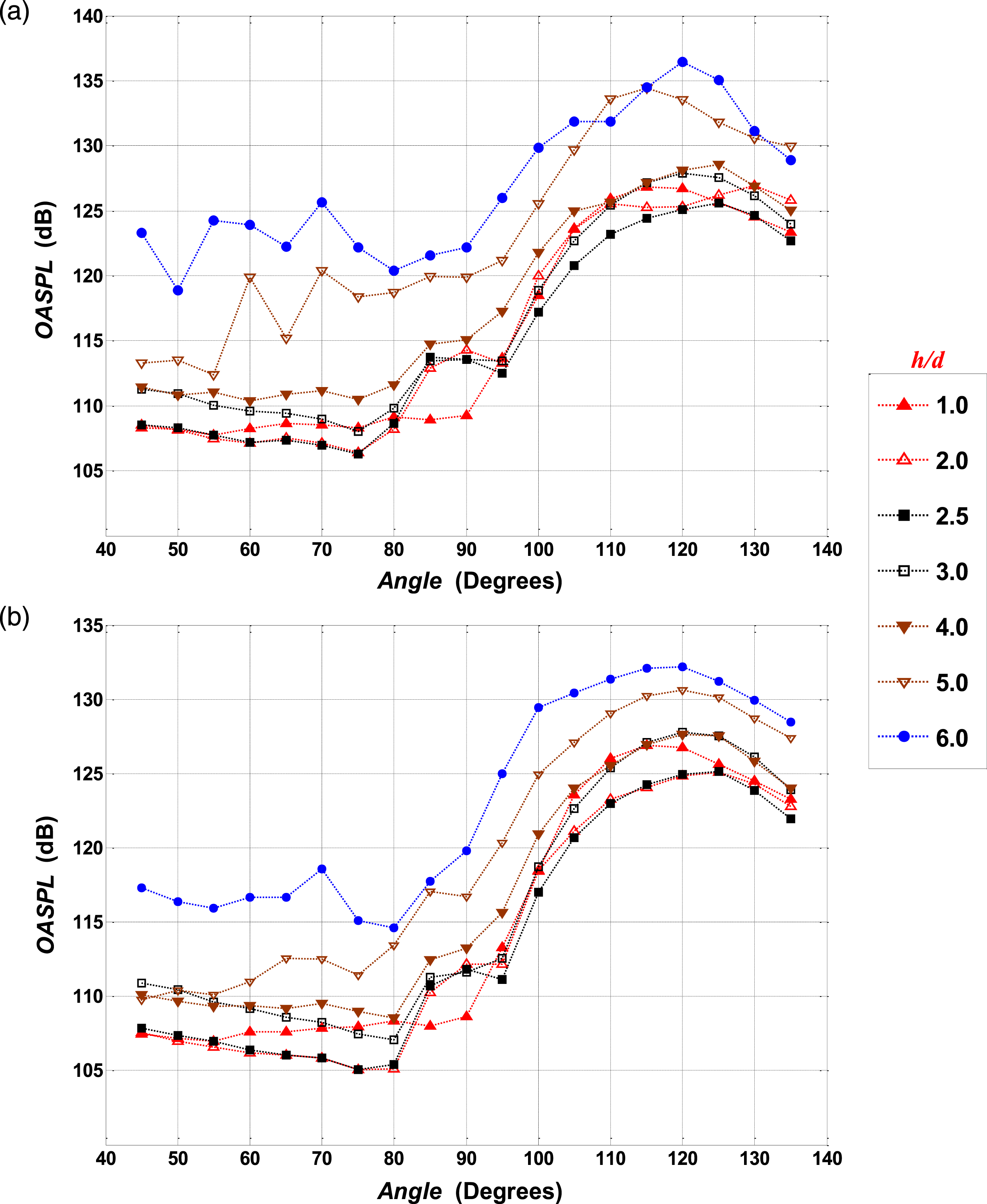
The effect of h/d is demonstrated for subsonic and supersonic conditions in Figures 14 and 15, respectively, for the impermeable plate. Similarly, Figures 16 and 17 are used to show the effect of h/d for jet impinging on a plate with 20 PPI at subsonic and supersonic conditions, respectively. Figure 14(a) clearly shows that OASPL increases with h/d up to h/d = 2.0 and then decreases. The maximum OASPL for NPR = 1.6 is found at h/d = 2.0. Similarly, in all subsonic cases, it is found that the maximum OASPL occurs at h/d = 2.0 due to the subsonic impinging tones. The maximum toneless OASPL is found at h/d = 1.0 [Figure 14(b)] instead of h/d = 2.0 [Figure 14(a)]. This is because the tonal strength is maximum for h/d = 2.0, compared to other standoff distances in the case of subsonic jets. Further, it is found that the OASPL variation with h/d is not clear in the case of supersonic-impinging jets compared to subsonic-impinging jets. Figure 15(a) shows that the maximum OASPL occurs at h/d = 5.0 and 6.0 for NPR = 4.0, depending on the direction. However, the toneless OASPL is maximum at h/d = 6.0 in all directions indicating the effect of tonal directivity. Like subsonic impinging jets, the toneless OASPL is not maximum at h/d = 2.0 for supersonic impinging jets. This is due to the presence of broadband shock-associated noise. In the case of permeable plates, the directivity pattern shows a decrease in OASPL from 35o to 85o-90o, and then a gradual increase up to 100o-120o depending on NPR and h/d, and then again, a decreasing trend. Figures 16(a) and 17(a) show the directivity pattern of OASPL for NPR = 1.6 and NPR = 4.0, respectively. The maximum OASPL occurs depending on the occurrence of tones. However, the toneless OASPL increases with h/d for all NPR for jets impinging on permeable plates. Figures 16(b) and 17(b) are used to show the toneless directivity pattern variation with h/d. These figures demonstrate that as h/d increases, the OASPL increases, and the trend becomes comparable to the free jet directivity pattern. The toneless OASPL directivity pattern is identical for all h/d values at constant NPR and all NPR at constant h/d for the particular permeable plate. In the next subsection, the effect of permeability on the directivity pattern is explained. Effect of h/d on directivity pattern at R/d = 40, for jet impinging on impermeable plate for NPR = 1.6 (a) with tone (b) without tone. Effect of h/d on directivity pattern at R/d = 40, for jet impinging on impermeable plate for NPR = 4.0 (a) with tone (b) without tone. Effect of h/d on directivity pattern at R/d = 40, for jet impinging on a permeable plate of 20 PPI for NPR = 1.6 (a) with tone (b) without tone. Effect of h/d on directivity pattern at R/d = 40, for jet impinging on a permeable plate of 20 PPI for NPR = 4.0 (a) with tone (b) without tone.


Effect of permeability
The directivity tests are performed for the impermeable plate (baseline) and three permeable plates at different h/d and NPR configurations. It is observed that the directivity patterns for all permeable plates are similar. Figure 18 is used to show the effect of permeability on OASPL at various angles, for different conditions. It is already seen in section 3 that the increase in permeability results in the reduction of OASPL. The directivity patterns in Figure 18 also shows the reduction in OASPL with permeability for all angles in front of the plate. Even though the mass flow rate or velocity behind the 10 PPI plate is more compared to 20 and 30 PPI, the OASPL is less for 10 PPI compared to others. This is due to the propagation of sound generated at the front side of the plate. However, the variation in the OASPL behind the plate is not only due to the flow permeability effect but also due to the sound absorption by the plate and transmission losses. OASPL directivity pattern at R/d = 40, for jet impinging on various permeability plates for (a) NPR = 1.8 at h/d =1.0, (b) NPR = 1.8 at h/d = 4.0, (c) NPR = 5.0 at h/d = 1.0 and (d) NPR = 5.0 at h/d = 4.0.
Spectral analysis
For three plates of different permeability and one impermeable plate placed at different positions and operated at various jet exit pressures, spectral analysis is carried out. In total, 360 cases are studied, and only some of the special cases are discussed here. The tonal behaviour is almost the same for all permeable plates. Figures 19–21 are used to show the directivity patterns for the frequency range of 1000 ≤ f ≤ 70000. Figure 19(a), (c), and (e) shows that the amplitudes at all the frequencies are higher in front of the plate when compared to the rear-side of the plate, due to the sound shielding (transmission losses) by the impermeable plate. The maximum SPL is found around 95° ≤ θ ≤ 110° for jet impinging on the impermeable plate at h/d = 2.0. Directivity pattern of SPL for frequency range 1000 ≤ f ≤ 70000 at R/d = 40, for jet impinging on Impermeable plate (a, c, e) and 20 PPI (b, d, f) placed at h/d = 2.0 for different NPR. Directivity pattern of SPL for frequency range 1000 ≤ f ≤ 70000 at R/d = 40, for jet impinging on Impermeable plate (a, c, e) and 20 PPI (b, d, f) placed at h/d = 2.0 for different NPR. Directivity pattern of SPL for frequency range 1000 ≤ f ≤ 70000 at R/d = 40, for jet impinging on Impermeable plate (a, c, e) and 20 PPI (b, d, f) placed at h/d = 5.0 for different NPR


For a particular h/d, the maximum SPL location depends on the jet velocity, wall jet velocity, and the refraction effect. Further, it is observed that the maximum SPL location shifts towards the jet axis as the nozzle-plate spacing increases. Generally, maximum SPL is observed around the wall jet spread angle. Figure 19(b), (d), and (f) shows similar patterns of SPL distribution in the front and rear-side of the plate for permeable plates. The maximum SPL is found around 110° ≤ θ ≤ 130° and behind the plate around 45°. It is also seen that the subsonic tones (Figure 19(a)–(d)) and transonic tones are present (Figure 19(e) and (f)) for both impermeable and permeable plates. However, the tonal amplitude is less for permeable plates. Figure 20 compares impermeable and permeable plates at h/d =2.0 for supersonic conditions. It is found that the turbulent mixing noise behavior is similar for permeable and impermeable plates in the subsonic case. However, due to the air passing through the permeable plate, there is an increase in the noise levels behind the plate. The discrete tones observed in the impermeable plate at supersonic conditions are absent for all permeable plates at h/d = 2.0. Figure 20(a) and (c) shows that impinging tones are present for the impermeable plate placed at h/d = 2.0 for NPR = 2.0 and 3.0. Figure 20(b) and (d) indicates that such tones are absent for jets impinging on permeable plates. Figure 20(e) shows the rich BBSAN for impermeable plates however BBSAN is absent for the jets impinging on permeable plates, as shown in Figure 20(f). Similar results are found for different h/d values. However, the supersonic impinging tones are observed at h/d ≥ 4.0 for a small range of NPR (Ref. jumps in OASPL at 2.8 ≤ NPR ≤ 3.2 as seen in Figures 5 and 6). Figure 21(a) and (b) shows strong and weak impinging tones at h/d = 5.0 and NPR = 3.0 for impermeable and permeable plate (20 PPI), respectively. However, the tones observed at h/d = 5.0 for NPR = 4.6 in the case of an impermeable plate, (Figure 21(c)) completely disappear when the plate is replaced by a 20 PPI permeable plate (Figure 21(d)). Similar results are observed for 10 and 30 PPI plates. Further, a detailed study reveals that the occurrences of these tones in the case of permeable plates are not due to the acoustic wave generated by the presence of the plate. These tones are generated at 2.8 ≤ NPR ≤ 3.2 are due to the oscillations of the second shock, like the free jet screech tones. Figure 21(c) and (e) show the presence of BBSAN for θ ≥ 110° in case of an impermeable plate. Whereas, for permeable plates, Figure 21(d) and (f) show the absence of BBSAN and the presence of weak BBSAN at NPR = 4.6 and NPR = 6.0, respectively.
Presence of tones in different configurations*.

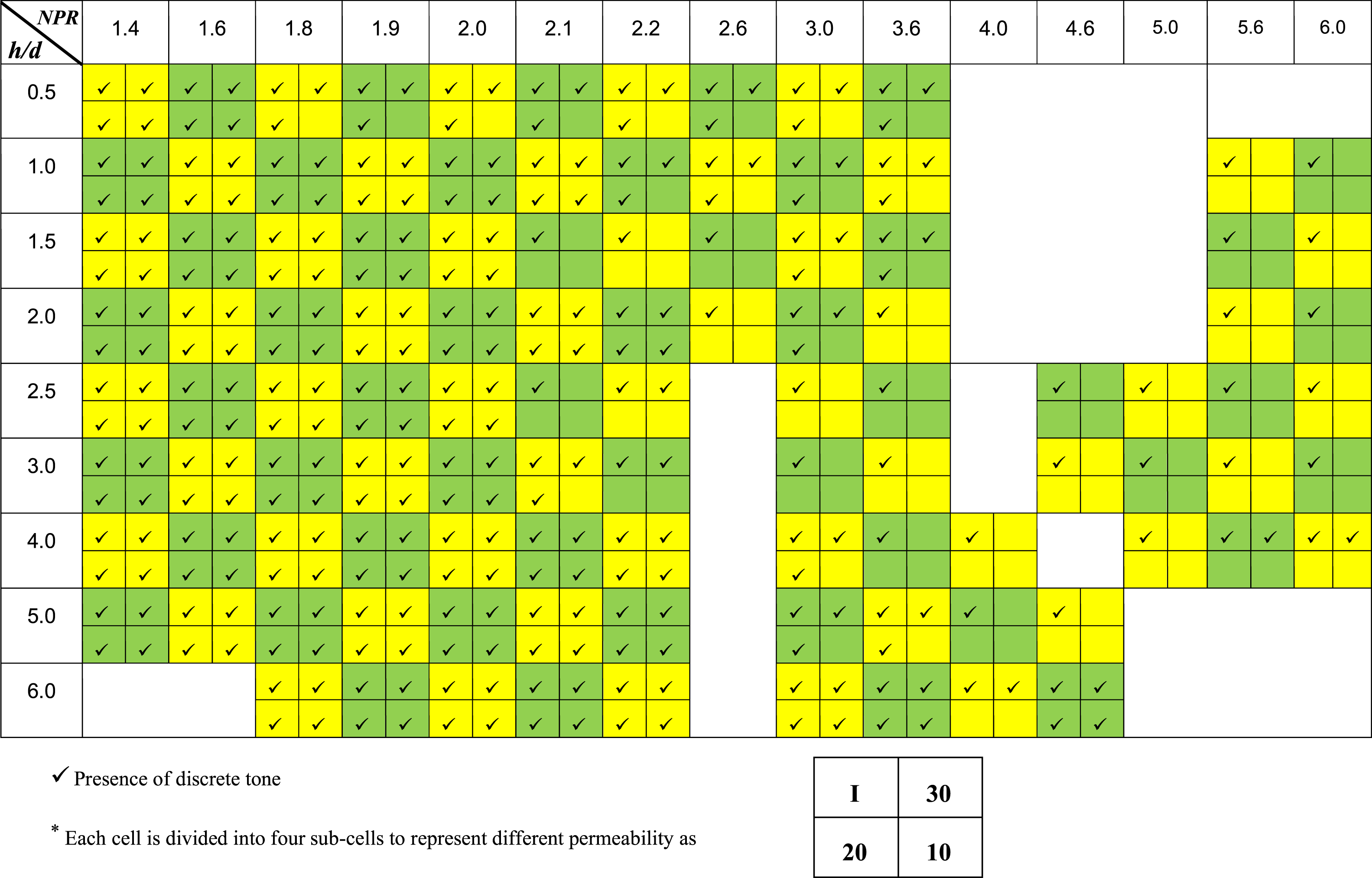
The absence of tones in the case of a supersonic jet impinging on the porous plate is contradictory to the observation of Wiley and Kumar. 45 However, the plates used in the present study are completely different from theirs. While the porous plates used in the present study have interconnectivity of pores, Wiley and Kumar 45 used perforated plates (through holes across the plate without any interconnectivity). Therefore, instead of using perforated plates, it is better to use porous plates with interconnectivity, as shown in Figure 3. This can reduce broadband noise as well as attenuate high amplitude impinging tones.
First, the spectral variation at R/d = 40 and θ = 135° is demonstrated for plates of different permeability values at subsonic and supersonic conditions. Then the tonal directivity is explored for the subsonic condition. Figure 22 shows the spectral comparison of the impermeable and permeable plates. Figure 22(a) indicates the presence of impinging tones for all the plates. It is seen that six impinging tones are present for all the plates studied irrespective of permeability. However, the amplitude and frequency of these tones vary with permeability in the subsonic region. In general, it is observed that the frequency increases and amplitude decrease with an increase in permeability. Apart from this, the low-frequency noise is dominant in the case of impermeable plates compared to permeable plates. Figure 22(b) shows dominant tones for the impermeable plates in the supersonic regime. These tones completely disappear when the plate is replaced by a permeable one. Spectral comparison of various permeable plates at R/d = 40 and 135o from jet axis for (a) h/d = 2.0 and NPR = 1.8 and (b) h/d = 5.0 and NPR = 4.6.
However, Table 2 shows some tonal appearance in the case of permeable plates. These are very weak tones compared to the tones present in the case of impermeable ones (not shown here). Further, the acoustic power of these plates is compared in the next subsection to see the overall effect.
Acoustic power
Similar to OASPL, acoustic power shows a non-monotonic variation with NPR and h/d due to the presence of impinging tones. Figure 23(a) shows the acoustic power variation with NPR and h/d for jet impinging on the impermeable plate. For this case, the acoustic power increases with an increase in h/d up to h/d = 2.0 and then decreases for NPR ≤ 2.0, whereas, for NPR > 2.0 the acoustic power shows a non-monotonic variation. The acoustic power of jet impinging on permeable plates is less compared to jet impinging on the impermeable plate for all NPR and h/d. Acoustic power variation with NPR and h/d for jet impinging on (a) Impermeable (b) 30 PPI and (c) 20 PPI plate.
It is interesting to observe that while the introduction of an impingement plate in front of a supersonic jet is expected to increase the noise, the contrary occurs if the plate is permeable. Figure 23(b) and (c) shows that the acoustic power is higher for a subsonic jet impinging on a permeable plate compared to the corresponding free jet, with the exact opposite happening for supersonic jets. Furthermore, it shows that the acoustic power increases with an increase in NPR at constant h/d and vice-versa. The enlarged view of Figure 23(b) and (c) shows that in supersonic regions for all h/d, the acoustic power decreases with an increase in permeability (h/d =2.5 and 6.0 are not shown). This is due to the absence of tones and mitigation of BBSAN in the case of permeable plates. Whereas, in the subsonic regions, the diluted subsonic tones are present and hence show non-linear behavior with respect to permeability for NPR 1.2-2.5. To understand, the subsonic tone strength reduction with respect to permeability requires a damping coefficient of the material, which is beyond the scope of this study.
Flow measurement
Measurements of wall jet velocity and flow velocity behind the plate are carried out using a pitot tube for jets impinging on impermeable and permeable plates. This measurement clarifies the turbulent mixing noise variation due to permeability.
Wall jet velocity measurement
The wall jet velocity measurement is carried out at r/d = 10 (where r is the radial distance from the centre of the plate as shown in Figure 1 for both permeable and impermeable plates at h/d = 5.0. It is found that a drastic reduction occurs in the wall jet velocity in the case of permeable plates (Figure 24). For simplicity, the maximum wall jet velocity is compared for the impermeable plate and 20 PPI plate in Figure 24. The cause of noise reduction in the permeable plate is the reduction of the mean velocity of the wall jet on the porous plate compared to the impermeable plate. The radiated acoustic power for the jet is given as (Blake)
52
Comparison of maximum wall jet velocity at r/d = 10 for h/d = 5.0.


where U
wj
is the wall-jet mean velocity, and functions f
2
, and f
3
incorporate the dependence of acoustic power on Reynolds and Mach numbers and the spacing. In present impinging plate keeping other parameter constant and neglecting nonlinearities involved due to the presence of feedback loop, it can be written as
Thus, from the Figure 24, it may be concluded that porosity causes reduction in the wall jet velocity and thereby reducing the acoustic power of jet impingement noise in front-side of the plate. It is very difficult to see the difference between wall jet velocity profiles of different permeable plates, as wall jet velocity variation is within the uncertainty limit of the digital manometer used in the present study.
Flow velocity behind the plate
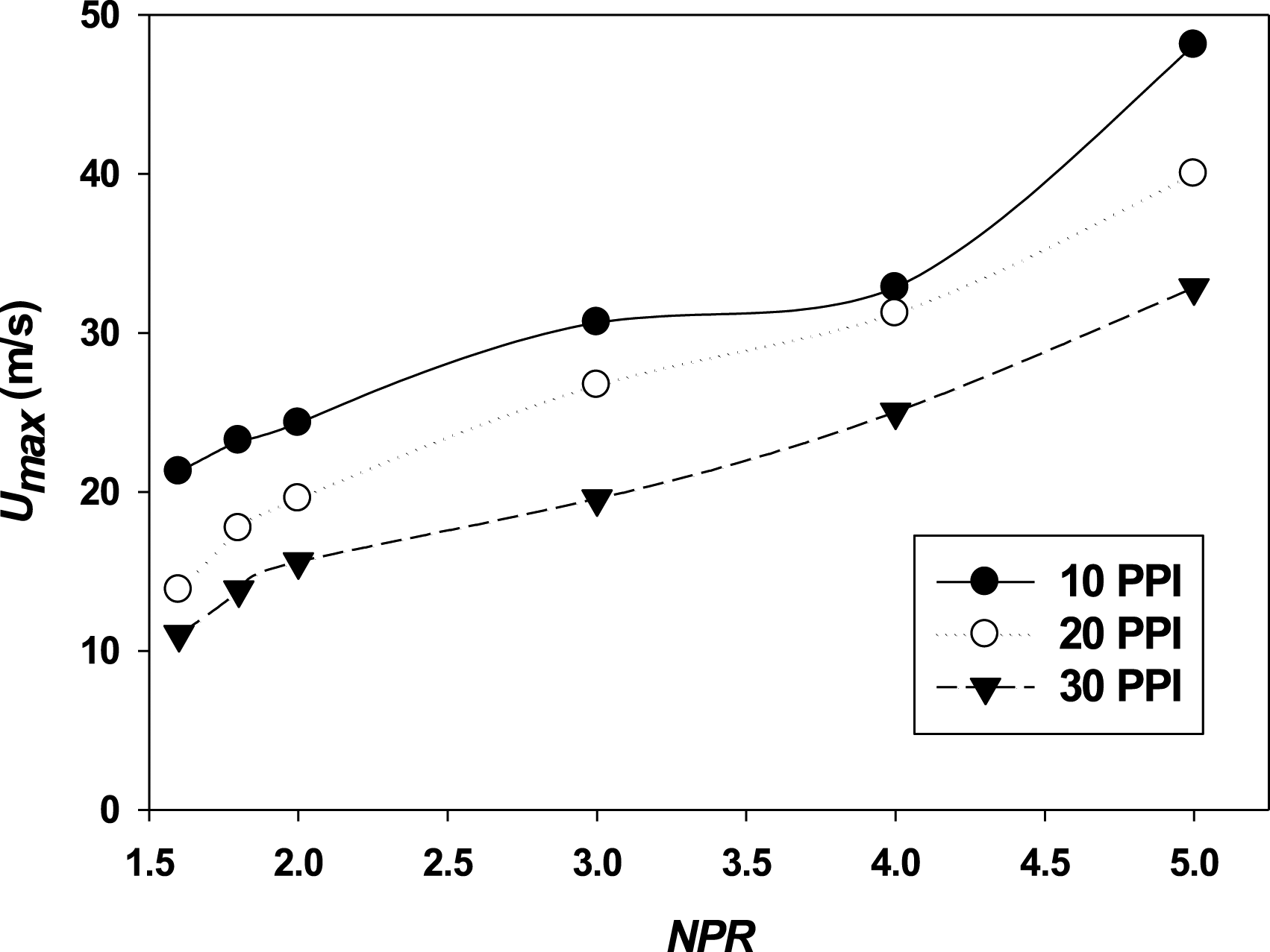
For obtaining further insights into the flow structure of jets impinging on porous plates, flow velocity behind the plate is measured at different locations. It is found that the velocity profile shows a smooth and almost symmetric variation beyond s/d = 4.0 (where s is the axial distance from the centre of the plate as shown in Figure 1, as shown in Figure 25. Therefore, the profiles are compared at s/d = 5.0 for different NPR in Figure 26. It is clear from Figure 26 that irrespective of NPR and porosity, the profile is symmetrical at s/d = 5.0. Hence, the maximum velocity at s/d = 5.0 is compared for various porosities at different NPRs. It is seen from Figure 27, that the maximum velocity is higher for 10 PPI compared to 20 and 30 PPI. One would expect that the higher velocity on the rear-side of the plate would lead to an increase in the noise level on the rear-side. However, the velocity field on the rear-side seems to play a much insignificant role compared to the sound propagation from the upstream side to the rear side through the plate. These aspects are understood from the results presented in Figures 24, 27, and 18. However, a detailed investigation of sound propagation through the porous plate is beyond the scope of the present study. Velocity profiles at various s/d for jet impinging on 30 PPI plate placed at h/d = 5.0 and NPR = 3.0. Velocity profiles of jet impinging on impermeable plate (a) 10 PPI and (b) 20 PPI placed at h/d = 5.0 for various NPR measured at s/d = 5.0. Comparison of Maximum velocity behind the plate at s/d = 5.0 for jet impinging on different permeability plates placed at h/d = 5.0 for various NPR

Flow visualization
The flow measurement carried out in the previous section is an intrusive method and measures only the time-averaged velocities. Therefore, the usefulness of such studies is limited to aspects such as turbulent mixing noise. However, unsteady effects such as the appearance and disappearance of tones cannot be resolved. Therefore, high-speed flow visualization is performed. The schlieren images are captured with the speed of 72000 frames per second with a resolution of 192×192 pixel-size. In the case of subsonic impinging jets, it is found that the coherent structures and their interaction with the obstacle are responsible for the impinging tonal feedback.16,17 Figure 28 shows a cycle of coherent structure generation and interaction with the impermeable plate located at h/d = 3.0 for NPR = 1.8. A similar phenomenon is observed for permeable plates, albeit with less intensity (pictures not shown). One complete flow oscillation cycle for jet impinging on an impermeable plate located at h/d = 3.0 and NPR = 1.8.
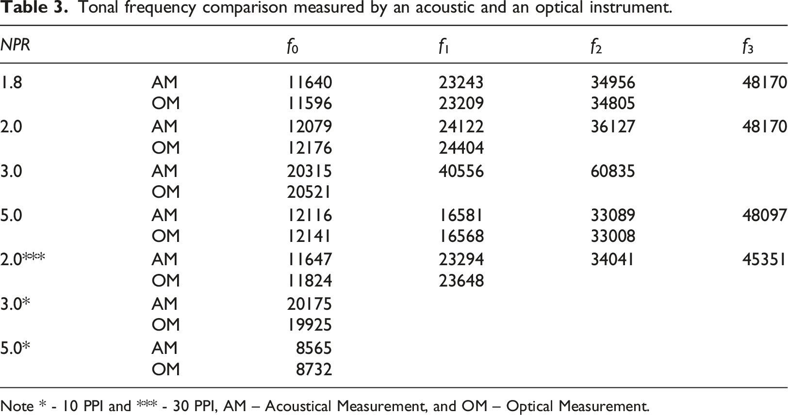
In the case of supersonic jets, the impinging tones are due to the feedback loop created by the acoustic waves generated by the shock oscillation. To demonstrate the shock oscillation six sequential images are chosen for jet impinging on permeable and impermeable cases. Figure 29(a) shows the shock oscillation in front of the impermeable plate, whereas the shock oscillation is not found in the case of any permeable plate [Figure 29(b)] Flow captured for jet impinging on (a) Impermeable plate (b) 20 PPI placed at h/d = 3.0 and NPR = 3.0. Tonal frequency comparison measured by an acoustic and an optical instrument. Note * - 10 PPI and *** - 30 PPI, AM – Acoustical Measurement, and OM – Optical Measurement.
Conclusion
In this comprehensive exploration, an in-depth investigation was conducted into the acoustic characteristics and pertinent flow parameters associated with jets impinging on a diverse range of permeable plates. A thorough comparison was made between the acoustic behavior of jets on permeable plates, impermeable plates, and free jets. Through meticulous blow-up and blow-down tests on various plate configurations, it was revealed that the noise levels decrease as the permeability increases within the NPR range of 1.5 to 6.0 and stand-off distances ranging from 0.5 to 6.0.
Notably, the investigation uncovered an intriguing absence of hysteresis when jets impinge on permeable plates, in stark contrast to the behavior observed with impermeable plates. Even though the OASPL is lower for subsonic jets impinging on permeable plates, the trend of variation with NPR remains like that of jets impinging on impermeable plates. Moreover, the introduction of permeable plates in supersonic jets results in reduced noise compared to the corresponding free jet, with the noise reduction increasing as the nozzle-plate spacing decreases.
Spectral analysis revealed a remarkable absence of most supersonic impinging tones in the case of permeable plates across all stand-off distances. However, subsonic and transonic tones still persist for jets impinging on permeable plates. Surprisingly, an increase in spacing leads to an increase in both turbulent mixing and broadband shock-associated noise for permeable plates, contradicting the behavior observed with impermeable plates. The toneless OASPL for permeable cases is significantly lower than that for impermeable cases across all NPR values, and it further diminishes with increasing permeability.
Additionally, a detailed directivity study demonstrated that both the OASPL and toneless OASPL increase with rising NPR at all angles for all plate configurations. While both subsonic and transonic tones are present for jets impinging on both impermeable and permeable plates, the amplitude of these tones is notably lower for permeable plates. Intriguingly, most cases of jets impinging on permeable plates exhibit an absence of supersonic impinging tones and broadband shock-associated noise. This suggests that permeable plates not only serve as a passive noise control mechanism for impinging jets but also for free jets operating under supersonic conditions. Placing permeable plates at strategic positions not only mitigates impinging tones but also reduces broadband shock-associated noise and turbulent mixing noise.
The investigation also involved flow measurements, which highlighted that the reduction in wall jet velocity is the key factor responsible for the decrease in turbulent noise observed with permeable plates. Furthermore, the alteration in the directivity pattern observed in permeable plates is attributed to the flow passing through the plate to the rear side and the propagation of sound through the pores of the permeable plate. Visualizing the flow provided compelling evidence that the absence of shock oscillation in front of the permeable plate contributes to the remarkable absence of impinging tones.
In conclusion, this comprehensive study unveils significant insights into the acoustic characteristics and flow parameters of jet impinging on various permeable plates. Permeable plates demonstrate remarkable potential as passive noise control mechanisms for supersonic impinging and free jets. They effectively mitigate impinging tones, reduce broadband shock-associated noise, and suppress turbulent mixing noise, offering significant acoustic performance improvements across engineering applications. The technique's only limitation is the need for careful selection of stand-off distances to achieve optimal noise reduction. Overall, permeable plates provide a powerful and versatile method for noise suppression, revolutionizing engineering practices and creating quieter environments.
Footnotes
Declaration of conflicting interests
The author(s) declared no potential conflicts of interest with respect to the research, authorship, and/or publication of this article.
Funding
The author(s) received no financial support for the research, authorship, and/or publication of this article.
