



Abstract
This paper introduces a passive protrusions to reduce undesirable structural loading and high-amplitude noise radiation in axisymmetric cavities, are common in industries, including pipelines and aerospace. A comprehensive experimental investigation of the pipe-cavity noise control system is conducted, exploring various protrusion locations and lengths at different Nozzle Pressure Ratios (NPRs). The study examines protrusions placed at the leading, trailing, and both leading and trailing edges of the axisymmetric cavity. Additionally, detailed experiments are performed to analyze the impact of protrusion lengths on unsteady cavity pressure and far-field noise radiation. Cavity pressure fluctuations and far-field noise levels are measured for both cases: with and without protrusions in the pipe-cavity setup. The Proper Orthogonal Decomposition (POD) technique is applied to the time-resolved Schlieren images to show the effect of passive protrusions on the exit jet flow structure. Results demonstrate that a protrusion located at the trailing edge yields superior noise reduction compared to other configurations. The efficacy of this protrusion in mitigating cavity noise is attributed to its ability to efficiently alleviate the feedback mechanism responsible for cavity noise generation and break down the recirculation region within the cavity system. Significant noise reduction, approximately 4 dB, is achieved at lower NPRs, and substantial noise reductions are also observed for the underexpanded jet condition.
Introduction
Axisymmetric cavities can produce high-amplitude acoustics and vibrations in pipeline industries, causing significant damage to structural parts and emitting strong resonance noise in the far-field. The flow over an axisymmetric cavity has been widely studied due to its relevance to many applications such as flow-induced vibration of power and process plant components, 1 coupling of flow and acoustics of annular flow restrictors in rocket combustion chambers, 2 dynamic behavior of flow and combustion in cavity flame holders of scramjet combustors,3–7 generation of acoustic energy in gate valves of steam pipelines, 8 and whistling behavior in side branch and periodic axisymmetric cavities, such as corrugated pipes. 9 Thus, the flow through the cavity can generate different modes of oscillations, such as longitudinal, 10 radial, 11 and diametral modes,12,13 due to the lock-on behavior of the shear layer oscillation and the natural frequency of the pipe-cavity system. Investigations of the diametral acoustic mode of the axisymmetric cavity have been reported in numerous applications, such as turbine valves,14,15 rockets,16–19 combustion chambers, 20 and pipes.21,22
Cavity-associated vibrations and acoustics can be effectively reduced using appropriate control strategies, divided into active and passive approaches. Active control methods rely on periodic actuation to disrupt the positive relationship between flow instabilities and acoustic oscillations in the resonator, leading to increased dampening and reduced noise levels, for example, upstream and cavity floor mass injection, loudspeakers, oscillating spoilers, and piezoelectric vortex generators. In contrast, passive control methods involve the modification of geometric features and do not require any periodic actuation. Examples of such methods include leading and trailing edge chamfers, fences, cylinders, steps at the leading edge of the cavity, leading-edge spoilers, and vortex generators.
Understanding the mechanism behind noise generation in a cavity is essential for devising effective control methods.23,24 The noise is primarily generated through complex interactions between the flow field and the cavity’s geometry, which can create strong acoustic feedback loops. As high-speed flow passes over the cavity, a shear layer forms at the cavity opening due to the interaction between the boundary layer and the cavity’s edges. This shear layer is highly susceptible to instabilities, which can cause oscillations and vortex shedding. These vortices impinge on the downstream edge of the cavity, generating sound waves that propagate upstream, interact with the shear layer at the leading edge, and create a feedback loop that amplifies the cavity resonance. The leading and trailing edges of the cavity are critical in this noise generation process. Modifications to these edges can alter the feedback loop by disrupting the vortex shedding and reducing the impingement of vortices on the cavity edges, thereby reducing noise.25,26 For instance, geometrical modifications such as chamfering or rounding the trailing edge of the cavity have been shown to weaken the feedback loop and attenuate cavity noise. 26 Additionally, introducing upstream obstacles like vortex generators and splitter plates can break up the coherent structures in the shear layer, reducing cavity resonance pressure fluctuations and noise. 27 A numerical study explored the use of leading-edge compression ramps, expansion surfaces, and mass injection for noise control in supersonic rectangular cavities. The results demonstrated that the compression ramp effectively weakens the shear layer, thereby reducing the sound pressure. 28 Similarly, upstream dimple-induced periodic vortex shedding has been employed to regulate flow oscillations within an open cavity. The dimples transition the laminar boundary layer to a turbulent state at the leading edge, thickening the boundary layer and stabilizing the shear layer. 29
The numerical work using LES 30 showed that modifications to the trailing edge of the open cavity were more effective in reducing noise than those to the leading edge. Specifically, the trailing-edge modification reduced the tonal noise by 18.7% and the overall sound pressure level (OASPL) by 6.04 dB in the far-field. In comparison, the longer leading-edge modification resulted in a tonal noise reduction of 30% and an OASPL reduction of 3.53 dB, while the shorter leading-edge modification achieved an 87.5% reduction in tonal noise and a 0.58 dB reduction in OASPL. The vortex shedding was weakened, resulting in an increased shear layer, due to the incorporation of a sub-cavity and an inclined baffle. Sunroof buffeting noise was reduced through the utilization of the sub-cavity, which had been positioned near the leading edge of the sunroof. 31 Experimental and numerical approaches were employed 32 to attenuate supersonic cavity noise using a sub-cavity within the main cavity. It was concluded that sub-cavities at both walls were more effective in attenuating the cavity noise than those at the front and rear. This is likely due to the avoidance of the direct impingement of the separated shear layer at the trailing edge of the cavity, resulting in a reduction of pressure fluctuations. 32 Moreover, placement of the sub-cavity alters the basic resonance mechanisms, such as fluid dynamic and fluid resonance oscillations. 32 Very few studies have investigated noise control in an axisymmetric cavity. A passive control approach was implemented using vortex generators, azimuthal dephasors, and compliant boundaries to reduce the self-sustained oscillation within the cavity, thereby decreasing axisymmetric cavity noise. 27 Adding a chamfer to the upstream and downstream edges of the cavity proved to be an effective strategy for reducing gate valve tonal noise. 24 Subsequent experiments to reduce trapped acoustic noise by implementing chamfers, rounding, and the addition of delta spoilers at the upstream and downstream edges of the cavity 33 indicated that this method was an effective tool for attenuating cavity resonance. In contrast to these passive approaches, active methods, such as cavity floor mass injection, have also been explored for controlling cavity resonance. Sarohia and Massier 34 attempted to control axisymmetric cavity noise through cavity floor mass injection, studying the noise generation mechanism for laminar and turbulent flows with varying cavity aspect ratios. Although active methods like mass injection can be effective in certain scenarios, they are often more complex, costly, and difficult to implement in practical applications, especially in industrial settings. Adding a chamfer to the upstream and downstream edges of the cavity proved to be an effective strategy for reducing gate valve tonal noise. 24 Subsequent experiments to reduce trapped acoustic noise by implementing chamfers, rounding, and the addition of delta spoilers at the upstream and downstream edges of the cavity 33 indicated that this method was an effective tool for attenuating cavity resonance. In contrast to these passive approaches, active methods, such as cavity floor mass injection, have also been explored for controlling cavity resonance. Sarohia and Massier 34 attempted to control axisymmetric cavity noise through cavity floor mass injection, studying the noise generation mechanism for laminar and turbulent flows with varying cavity aspect ratios. Although active methods like mass injection can be effective in certain scenarios, they are often more complex, costly, and difficult to implement in practical applications, especially in industrial settings.
Passive methods, such as geometric modifications (e.g., chamfers, spoilers), are often preferred because they are simpler, more cost-effective, and easier to implement and maintain. A comprehensive literature review reveals that the leading and trailing edges of a cavity play a key role in sound generation and mitigation. Hence, the effective alteration or placement of passive control devices near the leading and trailing edges of the cavity could effectively mitigate the noise level. This process is hypothesized to result from a feedback loop caused by oscillations in the shear layer and acoustic fields. To reduce the pressure fluctuations within the cavity, passive control method is proposed in the present study: using protrusions at various locations and of varying lengths. An initial set of experiments are conducted to identify the location with the greatest noise reduction capability. Subsequent experiments varied the protrusion length at the optimized location to maximize the noise reduction. A parametric study was performed to evaluate the effect of protrusions on the cavity noise in a wide range of jet flow speeds. Cavity pressure fluctuations and far-field acoustics were monitored to assess the sensitivity of the noise reduction to the position and length of the protrusion. Additionally, the downstream jet flow structure of the pipe-cavity without and with passive control is studied using the Proper Orthogonal Decomposition (POD) method.
Experimental setup
Anechoic jet facility and pipe-cavity system
Unsteady cavity pressure and far-field noise measurements are conducted at the Indian Institute of Technology Madras anechoic jet facility. The schematic of the test facility and the pipe-cavity system is illustrated in Figure 1. Acoustic foams are affixed to the wall, and the anechoic chamber has a cut-off frequency of approximately 700 Hz. A 4-inch pipe supplies filtered, dried air to the settling chamber, with a pressure regulator positioned upstream to regulate the stagnation pressure. This regulator maintains a constant air pressure entering the settling chamber at the desired level. The pipe-cavity assembly is attached to the end of the settling chamber for the duration of the experiments. It consists of an inlet pipe (length l
up
= 30 mm, diameter d
p
= 10 mm), an axisymmetric cavity (length L = 20 mm, depth D = 15 mm), and an outlet pipe (length l
dp
= 60 mm, diameter d
p
= 10 mm). The schematic of the anechoic jet facility is shown, with an inset detailing the pipe-cavity system and its nomenclature.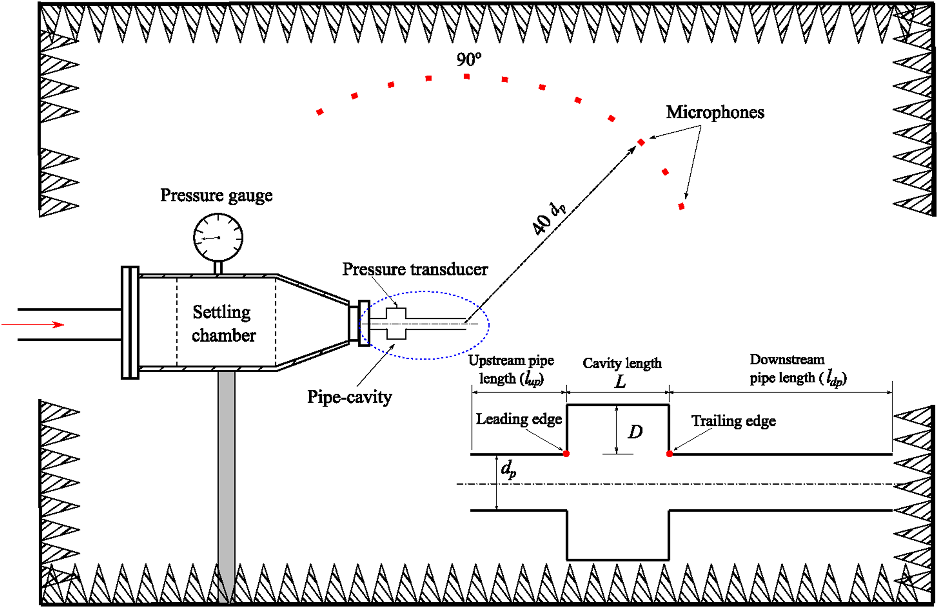
To reduce cavity pressure fluctuations and pipe-cavity jet noise radiation, a passive coaxial ring is attached at different positions within the cavity. Figure 2 illustrates the ring as a rectangular protrusion in a two-dimensional plane. The schematic in Figure 2 also shows the positions of the protrusions and the associated terminology within the pipe-cavity. The protrusions are located at the leading edge (LE), trailing edge (TE), and both leading and trailing edges (LE & TE). The protrusions have a length of l = 3 mm, a radius of r = 7.5 mm, and a thickness of t = 3 mm. To compare their effectiveness, a baseline cavity without protrusions is also evaluated. Experiments are conducted on protrusions with various locations, a fixed length, and thickness. The location is then optimized, and investigations are undertaken with varying protrusion lengths ranging from 3 mm to 6 mm in increments of 1 mm. Protrusions are tested for a wide range of nozzle pressure ratios (2.0 ≤ NPR ≤5.0), encompassing both low and moderate under expanded jet conditions. The schematics of (a) Baseline model and protrusions at (b) Leading Edge (LE), (c) Trailing Edge (TE), and (d) Leading and Trailing Edges (LE & TE).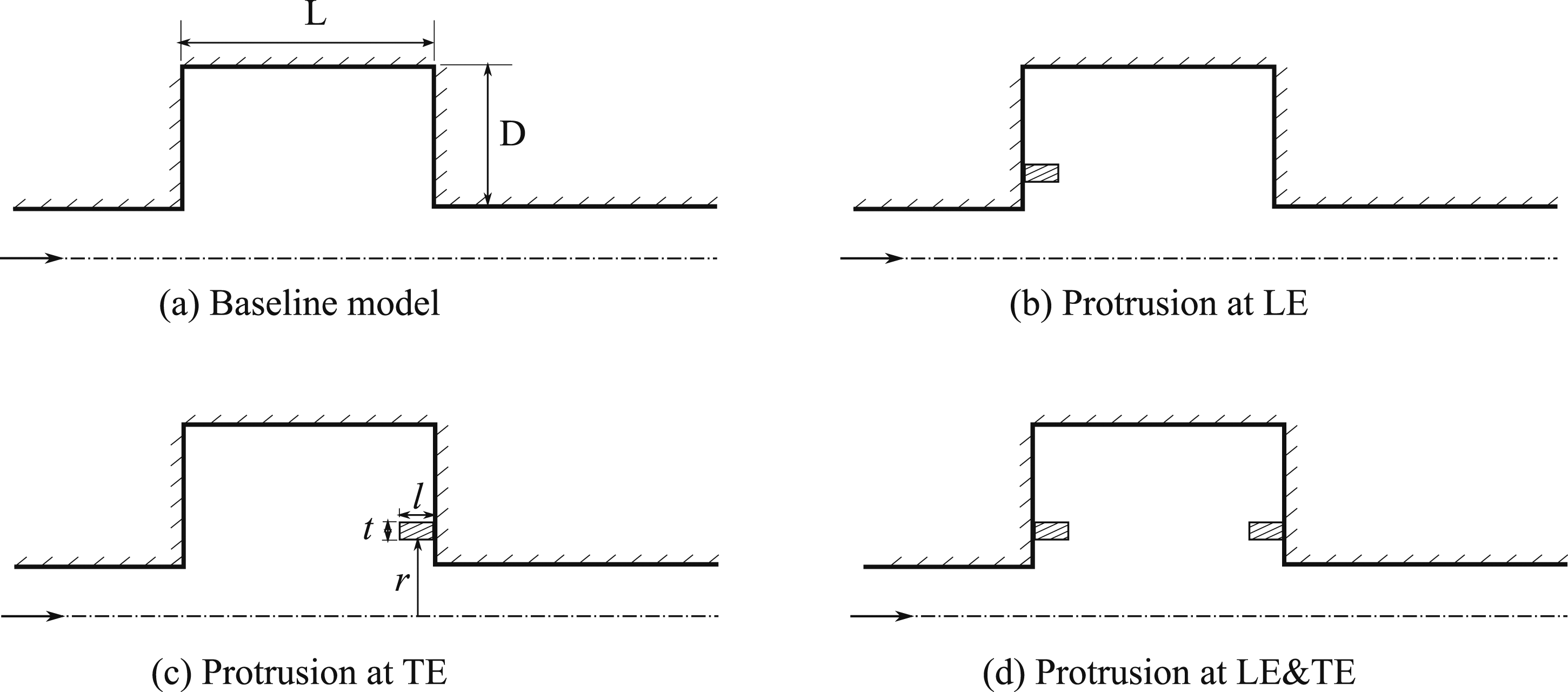
Instrumentation and uncertainty analysis
PCB Piezotronics M101A06 pressure transducers and 1/4 inch free-field condenser PCB microphone (PCB-377A01) are used to measure cavity pressure fluctuations and far-field acoustic measurements, respectively. Both transducer and microphone are calibrated before experiments and found to have sensitivities of 1.45 mV/kPa and 3.4 mV/Pa at 250 Hz, respectively. The transducer, positioned at L/2, is placed at the wall of the cavity, and the microphone is located 40d p away from the jet center. Experiments are conducted with a sampling rate of 150-kilo samples per second and acoustic spectra are computed using the Welch’s method. 35 An analog filter is used to avoid aliasing error, and the results are presented in terms of spectral analysis, root mean square of the cavity pressure (P rms ), and the directivity analysis is also performed using OASPL. The uncertainties and repeatability of measurements in this experimental study are as follows: The diameter of all circular pipes is measured with an uncertainty of ± 0.04 mm, and the piezoresistive pressure transducer with an uncertainty of ± 0.2% of full scale. Microphone positioning uncertainty is ± 1 mm, while the angular traverse used for the directivity study had a positioning error of ± 1o. Sound pressure levels are referenced to 20 μPa, with a repeatability error estimated at ± 1 dB.
The dynamics of downstream jet structures are investigated using high-speed Schlieren imaging technique. A simple inline schlieren arrangement for jet flow visualization is used. Photron PFV4 software captures high-speed schlieren images. A variable-intensity LED emits green light, refracted through lenses with a test section in between. Images are acquired using a Photron FASTCAM UX 100 high-speed camera at 32 kHz, with a knife-edge adjusting sensitivity by cutting 50% of light.
Results and discussion
The protrusions are expected to reduce noise by affecting the feedback mechanism, which helps dissipate sound waves, and by alleviating the recirculation vortex structure within the cavity, which disrupts sound propagation. To investigate noise attenuation levels, root mean square pressure (P
rms
) and spectral analysis of cavity pressure fluctuations and sound pressure spectra, as well as the OASPL of far-field noise, are performed. Results demonstrate that these two primary mechanisms effectively reduce noise and pressure fluctuations on the surface of the cavity. Firstly, the baseline acoustics, i.e., without protrusion, are presented to provide the nature of cavity pressure and associated far-field noise. Figure 3 illustrates the power spectrum and coherence spectrum of cavity pressure fluctuations and far-field noise at an NPR of 2.0, with the microphone positioned at θ = 40°. The data show that the axisymmetric cavity produces high-amplitude narrowband tones, a result indicative of the fluid resonant behavior within the cavity. This observation is significant, as it supports the hypothesis that strong tonal noise is a result of acoustic feedback mechanisms in the cavity system. (a) Power and (b) coherence spectra of cavity pressure fluctuation and far-field noise.
In order to better understand the underlying oscillatory frequency of these tones, a theoretical model is applied to predict the natural frequency of the pipe-cavity system under no-flow conditions, as described by equation (1).
36


The cavity radius, R c , is the sum of the pipe radius, R, and the cavity depth, D, thus R c = R + D. The Bessel coefficient for the first tangential mode is denoted α01. 36 The primary tonal noise observed for both cavity and far-field noise at f = 5053 Hz corresponds to the first tangential mode of cavity oscillation as calculated using equation (2), indicated by the red dot marking the peak of the tone. Similar tones are also observed in the far-field noise, as confirmed by the coherence spectra, where high amplitude coherence levels are observed at 2f(0,1,0), indicated by the blue dot. This result aligns with the observations of.10,37 In this study, focus is primarily directed toward the primary acoustic modes associated with the axisymmetric cavity, with specific attention to the first tangential mode. This mode is identified as dominant in producing high-amplitude tonal noise. This frequency was selected for its significant contribution to generating elevated acoustic pressure levels within the cavity, positioning it as central to the investigation of noise reduction achieved through passive protrusions. Consequently, a D/L ratio of 0.75 was chosen based on prior findings, 10 where it was observed to yield the highest amplitude noise levels at higher Mach numbers due to the prominence of the first tangential mode.
Effect of protrusion locations on cavity acoustics
Cavity pressure fluctuations are measured to analyze the aerodynamic and acoustic pressure loading of cavities with and without (baseline) protrusions. The P
rms
results can offer insight into acoustic energy distributions resulting from fluid-resonant cavity pressure fluctuations.10,11 The findings are leveraged to better understand the radiated noise caused by acoustic flow coupling in the cavity system.
10
The variation of P
rms
with stagnation pressure is an important metric that can be used to determine the detrimental impact of cavity structures in supersonic flow.38,39 Figure 4 illustrates the variation of Prms for different cases to identify the protrusion location that produces the most effective noise reduction. With an increase in momentum of the jet, due to the rise in the NPR, the P
rms
increases due to the increased shear layer convection and compressibility. This finding is consistent with the observations made by
39
in the context of supersonic flow over a cavity. A substantial decrease in P
rms
is observed for the protrusion located at the trailing edge of the cavity compared to the leading edge and baseline model. This result indicates a significant reduction in aeroacoustic loading on the cavity walls when the protrusion is situated at the TE. A maximum P
rms
reduction of approximately 1 × 10⁴ Pa is observed for TE protrusion compared to the baseline at NPR = 5. Conversely, an appreciable noise increase is observed in the case of a protrusion at the leading edge. Furthermore, the LE & TE case displays a considerable decrease in P
rms
, indicating that the trailing edge and LE & TE locations are effective for reducing the root mean square of unsteady cavity pressure fluctuations. Variation of P
rms
with NPR for different protrusion locations and compared with baseline (without protrusion).
The impact of the observed variation in the pressure fluctuations, as well as the relative contributions of tonal and broadband spectral components to overall P
rms
levels at various frequencies, can be identified through analysis. Hence, the power spectral analysis of cavity pressure fluctuation is carried out and plotted in Figure 5. Figure 5 shows the power spectral comparison of unsteady cavity pressure at different protrusion locations with the baseline pipe-cavity. Results are presented for different NPRs. The spectra are highly dominated by narrowband tonal noise associated with cavity resonance and exhibit a strong peak at the first tangential mode of the pipe-cavity. The inset shows the variation in tonal noise at the fundamental and first harmonic of the cavity resonance for NPRs 2.0 and 5.0 for varying protrusion locations. As shown in Figure 5, the spectra reveal that the primary frequency of oscillation is 5053 Hz, which is in line with the predicted frequency (f(0,1,0) = 5068.9 Hz) of the first tangential mode of the pipe-cavity, as indicated by equation (2). The obtained results are compared with the finite element numerical simulation of an axisymmetric cavity at L/D = 0.75 by Baskaran and Srinivasan
10
as presented in Table 1. However, the frequency of the cavity pressure changes slightly due to the protrusions, as observed in the inset figures. The TE and LE & TE configurations decrease P
rms
, as demonstrated by a decrease in PSD, compared to the reference case without protrusions. In the slightly under-expanded jet at NPR = 2, the first tangential mode of oscillation exhibits a reduction of 2.21 × 10¹⁰ Pa2/Hz in the PSD, while the first harmonic shows a reduction of 2.41 × 10⁷ Pa2/Hz. For the under-expanded jet at NPR = 5, the first tangential mode experiences a reduction of 3.31 × 10¹¹ Pa2/Hz in the PSD, and in the first harmonic, there is a reduction of approximately 2.81 × 10⁶ Pa2/Hz for TE compared to the baseline. Additionally, spectral comparison indicates notable noise reduction in the higher harmonics. However, there is no significant change in the broadband noise amplitude. Based on the above results, it is evident that the protrusion at the TE case effectively reduces the cavity noise. PSD of unsteady cavity pressures variation with NPRs (a) NPR = 2.0, (b) NPR = 3.0, (c) NPR = 4.0, and (d) NPR = 5.0.

Effect of protrusion locations on far-field noise
The effect of the hydrodynamic and resonant fields of the upstream cavity on the radiated pipe-cavity jet noise is significant. 10 This section presents results demonstrating the effect of the upstream pipe-cavity on the jet noise for the baseline and different protrusion locations and lengths. A directivity study is conducted to analyze the angular variation of the acoustic field for different NPRs.
Figure 6 shows the OASPL as a function of the emission angle (θ) for NPRs 2.0, 3.0, 4.0, and 5.0. The OASPL for different protrusion locations is compared with the baseline. At NPR = 2.0, sound pressure gradually decreases as the emission angle increases for all cases. This result is consistent with the P
rms
and PSD of cavity pressure fluctuations. Moreover, it is observed that the maximum OASPL is in the range of 40° ≤ θ ≤ 60°. This result is in agreement with the findings of Sarohia and Massier
34
and Baskaran and Srinivasan
10
for pipe-cavity jet cases. The maximum noise radiation occurs for protrusion at the leading edge, and the OASPL for TE and LE & TE cases is consistently lower than the baseline across a wide range of θ. Specifically, the maximum OASPL reduction is approximately 2 dB for the TE case. A change in the directionality of OASPLs is observed due to shock-generated noise as NPR increases, as reported by Tam.
40
At NPR = 3.0, the maximum noise radiation is observed at 40° for the baseline and protrusions. However, interestingly, the TE and LE & TE cases show an increased OASPL in the 80° ≤ θ ≤ 130° range. OASPL is higher in this range for TE and LE & TE compared to baseline and LE cases. The maximum noise radiation occurs at 40° and 90°. In a simple under-expanded pipe jet, the greatest noise radiation is at an emission angle of 90°.
40
Conversely, in a pipe-cavity under-expanded jet at NPR = 4.0, the maximum noise radiation occurs in the range of 40° ≤ θ ≤ 60° and 80° ≤ θ ≤ 100°. The TE case also shows a reduction in the OASPL trend compared to the baseline case and other protrusion locations. Figure 6 supports this conclusion, indicating that the TE protrusion efficiently reduces noise at various NPRs and emission angles. Directivity of different arrangements (a) NPR = 2.0, (b) NPR = 3.0, (c) NPR = 4.0, and (d) NPR = 5.0.
In the case of under-expanded jet conditions, an undulated trend in the OASPL is observed with changing emission angles. The highest noise radiation is observed at 40°, and the OASPL hump is in the range of 70° ≤ θ ≤ 110°, likely due to the interaction between shockwaves and the turbulent shear layer in the jet. In under-expanded jets, shock cells form within the jet due to the mismatch between the exit pressure and ambient pressure, leading to a series of compression and expansion waves. These shockwaves interact with the turbulent structures in the shear layer, amplifying pressure fluctuations and radiating strong acoustic waves. This interaction can lead to high noise levels at certain emission angles, particularly in the downstream direction, where the shock-shear layer interaction is most intense. The constructive interference of these acoustic waves, along with the periodicity of the shock cells, contributes to the observed increase in the OASPL at these angles. When different protrusion lengths are compared, it is shown that all TE protrusions reduce the sound pressure, as seen in the NPR = 4.0 and 5.0 cases. At both of these NPRs, the 4 mm protrusion case effectively reduces pressure fluctuations and radiated noise.
This study investigates the directional behavior of peak PSD variations of the first three tones for different protrusion locations. Figure 7 presents the change in the fundamental tonal amplitude of the PSD for various protrusion locations, such as LE, TE, LE & TE, and baseline. An increase in NPR results in an increase in the tonal amplitude. The fundamental tone is radiated towards the emission angle of 40°. However, a decreasing trend in PSD is noticed at higher emission angles. The fundamental tonal amplitude for the baseline is higher than for passive control methods (protrusions) across a wide range of NPRs. This indicates a significant reduction can be achieved with protrusions at different locations for lower emission angles. In contrast, an increase in the emission angle leads to no significant difference in PSD amplitude for protrusions compared to the baseline. The PSD of the first tangential mode of the cavity reduces by an order of magnitude due to the presence of protrusions compared to the baseline. Directivity of PSD of fundamental tone different arrangements at (a) NPR = 2.0, (b) NPR = 3.0, (c) NPR = 4.0, and (d) NPR = 5.0.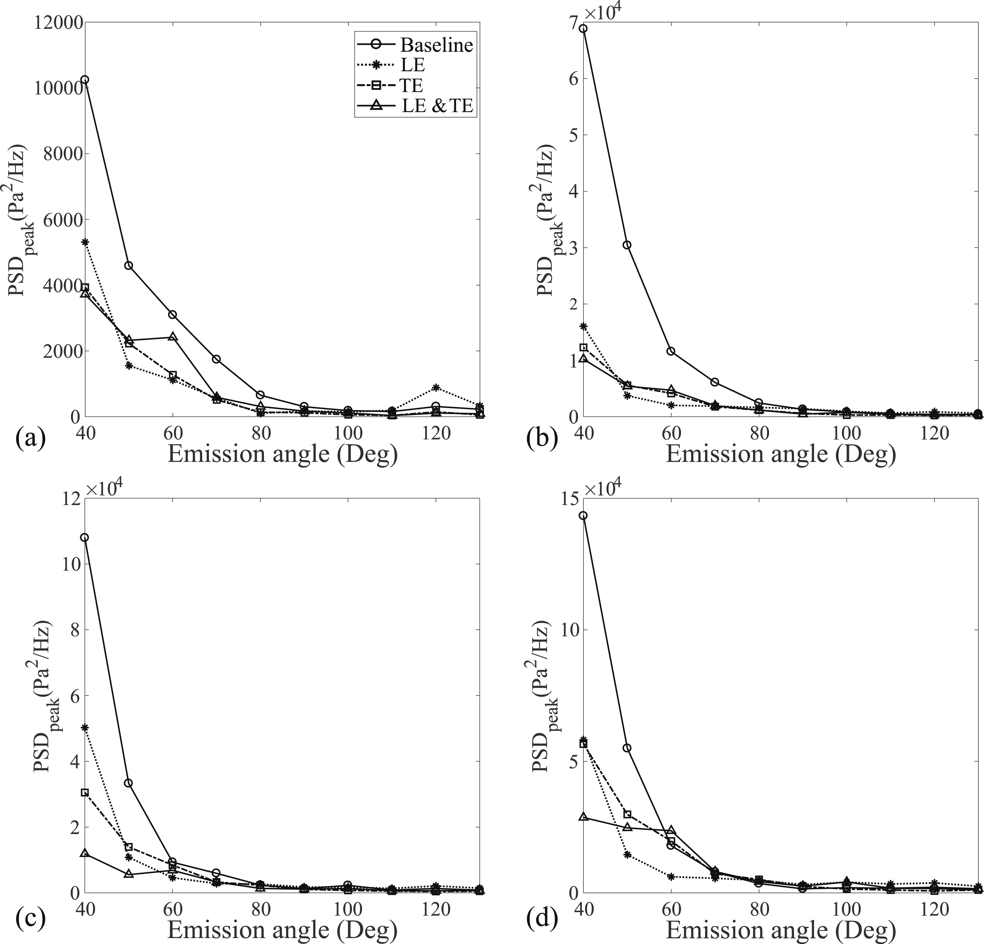
Figure 8 shows the variations of the first harmonic of the first tangential mode of the pipe-cavity. The amplitude of the first harmonic is greater than that of the fundamental tonal amplitude. This result is inline with our previous findings.10,37 The PSD of the first harmonic is more prominently directed towards 40o for lower NPR values. Whereas, for NPRs ranging from 3.0 to 5.0, the maximum noise radiation is observed in the 40o - 60o range. The LE protrusion case exhibits a higher PSD amplitude than the baseline and other protrusions when NPR is 2.0. Nevertheless, for higher NPRs (under-expanded jet conditions), the baseline case demonstrates a higher PSD than the protrusions. Overall, the TE and LE & TE cases appear to be effective control locations for cavity-associated jet noise, as illustrated in Figure 7 for a broad range of NPRs. Directivity of PSD of first harmonic different arrangements at (a) NPR = 2.0, (b) NPR = 3.0, (c) NPR = 4.0, and (d) NPR = 5.0.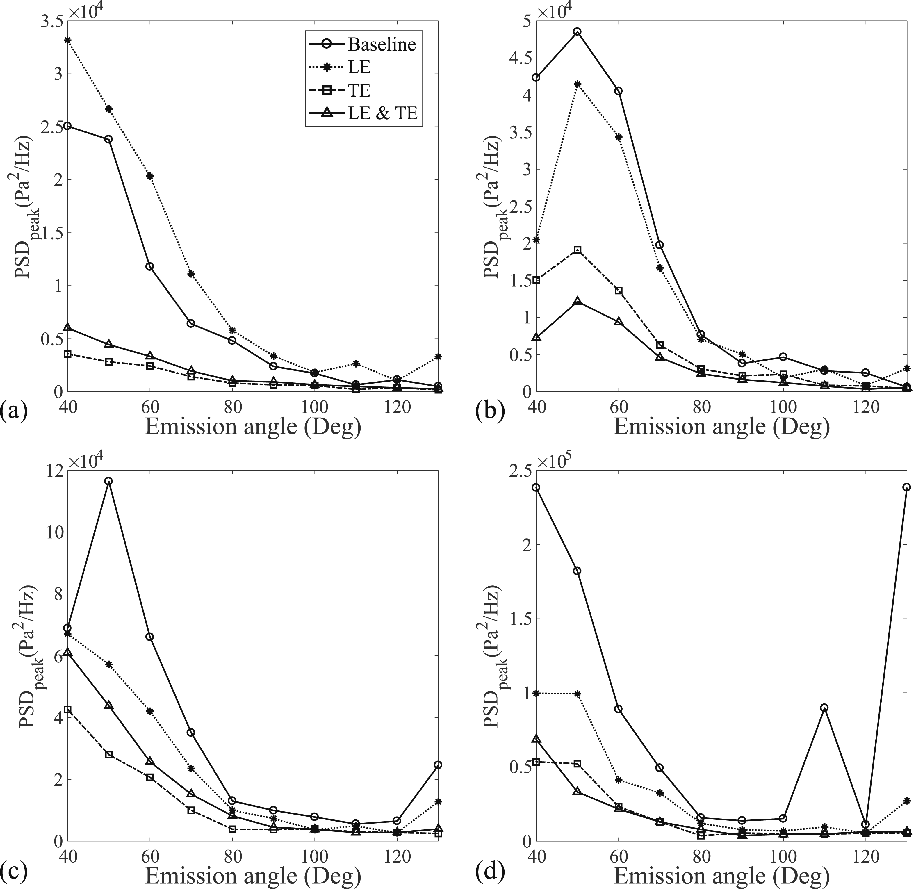
Effect of protrusion lengths on cavity acoustics
To explore the efficacy of the TE protrusion in reducing unsteady cavity pressure, a parametric analysis is carried out to assess the influence of varying protrusion lengths at the same radial location on noise reductions.
Figure 9 shows the P
rms
of the unsteady cavity pressure for baseline (without protrusion) and different protrusion lengths. An increase in the protrusion length leads to a decrease in P
rms
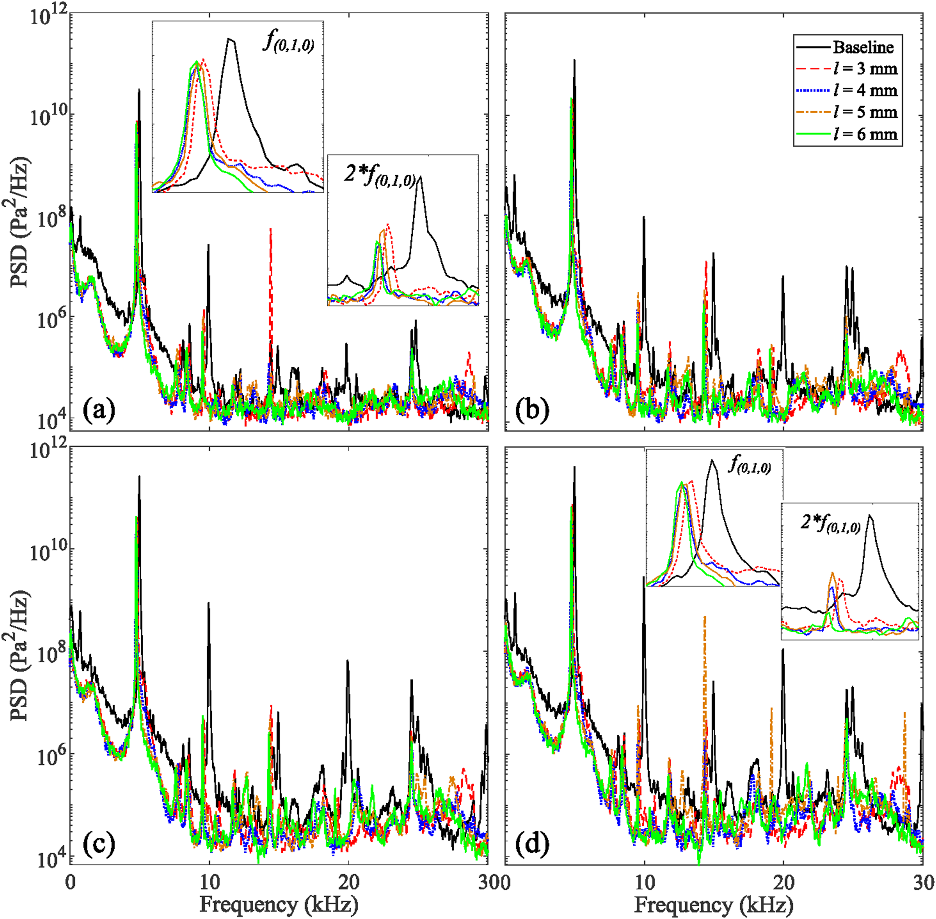
, reaching a maximum reduction at a length of 4 mm, as shown in Figure 9. Further increase in the protrusion length leads to a slight rise in P
rms
. Therefore, it can be concluded that a 4 mm protrusion is the most efficient for attenuating pressure fluctuations. The variations of PSD of different protrusion lengths for the range of NPRs are further highlighted using power spectral analysis and depicted in Figure 10. An increase in protrusion length leads to a small decrease in the frequency of oscillations while the amplitude of the PSD is significantly reduced. The insets (Figure 10) highlight the noise variations of different protrusion lengths at the fundamental and first harmonic of the first tangential mode of the cavity for NPRs 2.0 and 5.0. The primary tonal amplitude comparison shows a considerable noise reduction, and the secondary tone significantly reduces noise. Additionally, harmonics are also attenuated with an increase in protrusion lengths. These findings support the earlier conclusion that the protrusion at 4 mm is effective compared to others. Comparison of P
rms
variation for different lengths of the TE protrusions. PSD comparison of different sizes of protrusions (TE case) at (a) NPR = 2.0, (b) NPR = 3.0, (c) NPR = 4.0, and (d) NPR = 5.0.
Effect of protrusion lengths on far-field noise
Figure 11 shows the variation of OASPL with different emission angles when varying the protrusions’ lengths. These results are consistent with the unsteady cavity pressure variations. At NPR = 2.0, all TE protrusion lengths are found to decrease sound pressure compared to the baseline. It is observed that the maximum noise radiation occurred at emission angles of 40o ≤ θ ≤ 60o. An increase in protrusion length reduced OASPL; however, a further increase caused a slight rise in OASPL. The 4 mm case effectively reduces sound pressure, leading to a maximum OASPL reduction of 3 dB at lower emission angles. In the case of NPR = 3.0, the maximum noise radiation occurs at lower emission angles, and the OASPL decreases with increased emission angles. The undulated OASPL trend is observed for 3 to 5 mm protrusion lengths. Initially, all the protrusion lengths show a lower OASPL than the baseline for lower emission angles. However, with protrusion length of 3 mm shows the noise increment compared to baseline in the range of 80o ≤ θ ≤ 130o. The 4 mm case shows lower OASPL for lower emission angles, and the 6 mm case shows significant noise reduction for higher emission angles. The maximum OASPL reduction is observed at about 4 dB. Directivity of different size of protrusions at (a) NPR = 2.0, (b) NPR = 3.0, (c) NPR = 4.0, and (d) NPR = 5.0.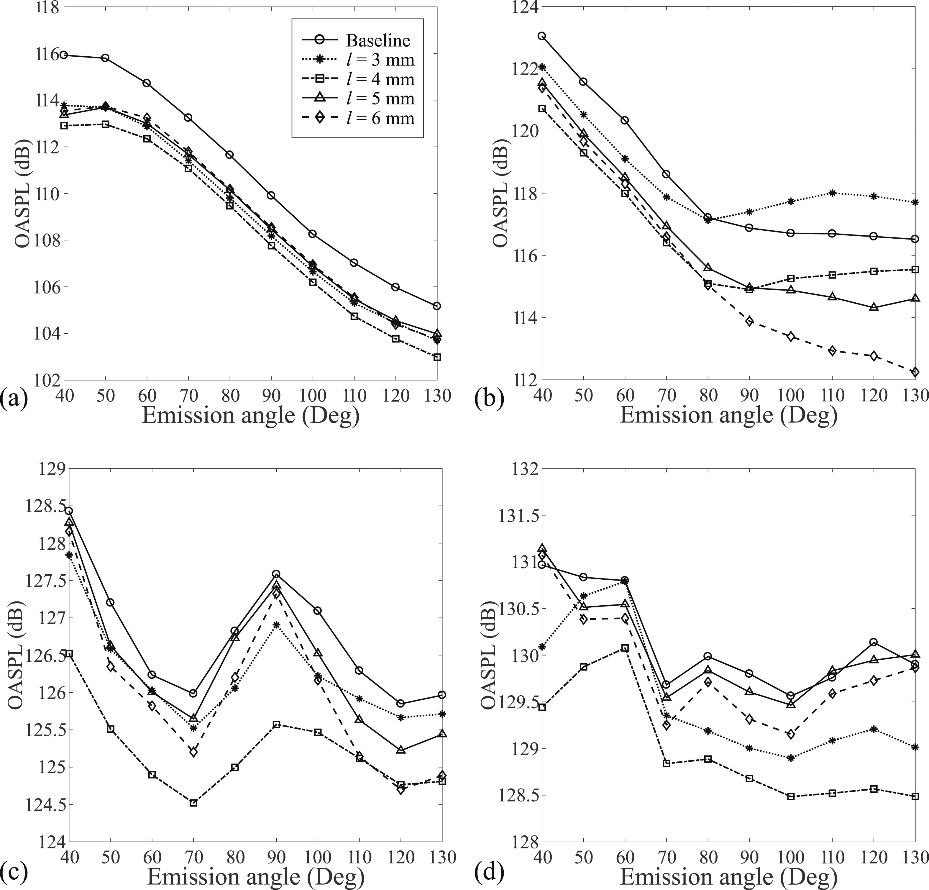
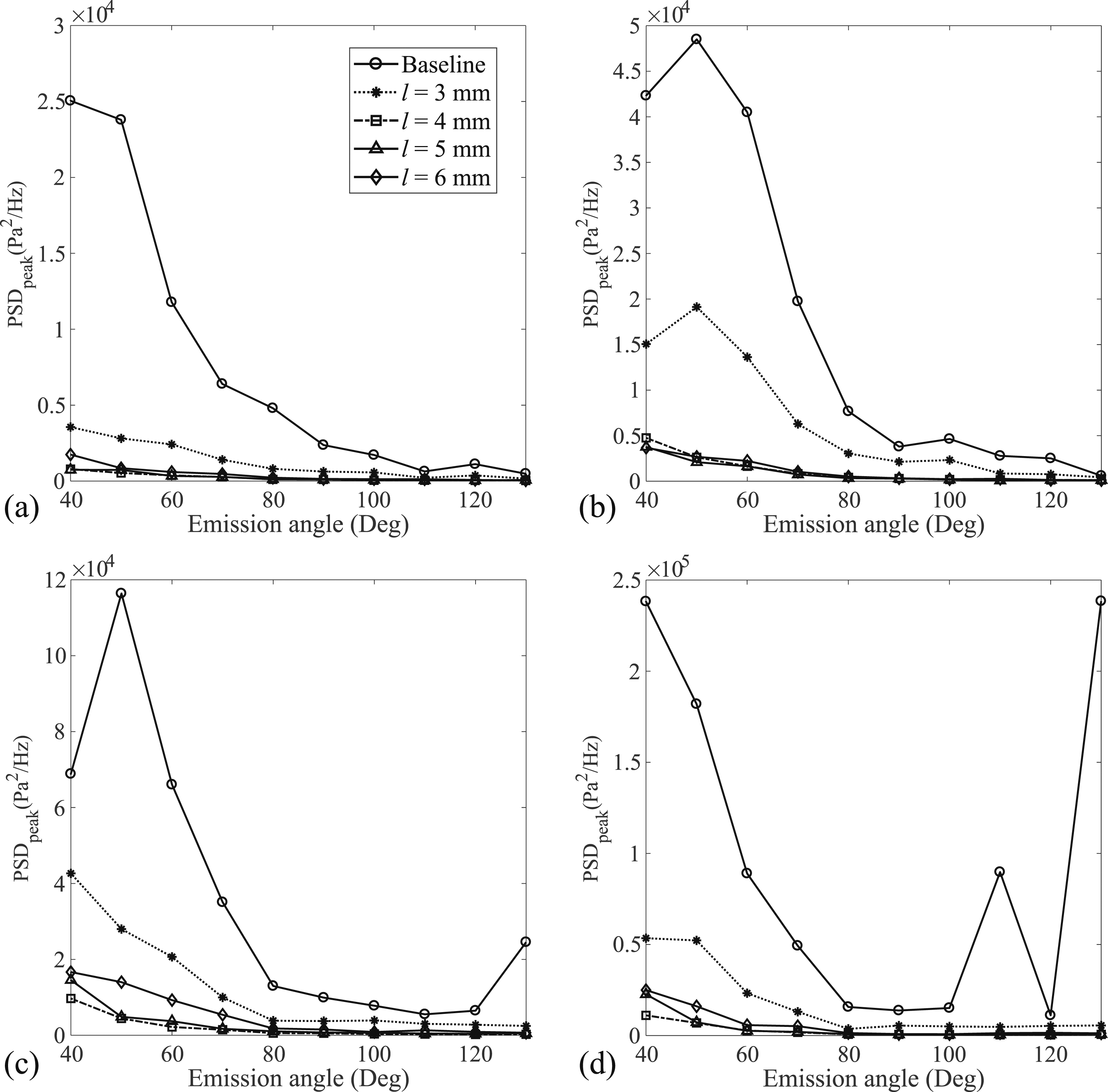
It is understood that the TE protrusion is an effective location for noise reduction. This section presents the variation of the fundamental tonal amplitude of the PSD for different TE protrusion lengths for 3, 4, 5, and 6 mm and baseline. Fundamental tones of both the TE protrusions and baseline are radiated towards the lower emission angle as seen in Figure 12. However, a further increase in emission angle shows a decreasing trend in PSD. The fundamental tonal amplitude is higher for baseline than TE protrusions for a wide range of NPRs. The results indicate that significant PSD reduction is attained through different TE protrusion lengths for lower emission angles. However, an increase in emission angle shows no significant difference in PSD amplitude for protrusion lengths than baseline. The PSD amplitude decreases with increased protrusion lengths and reaches the maximum noise reduction for 4 mm cases. A further increase in TE protrusion length leads to a small increase in noise. The variation of PSD of the first harmonic of the cavity tone for different TE protrusion lengths is shown in Figure 13. Generally, PSD is found to be more directive to lower emission angles for all NPRs. However, at NPR = 5.0, PSD is observed to be high for both lower and higher emission angles. Compared to the fundamental tone, the amplitude of the first harmonic is higher for a wide range of NPRs. Moreover, significant noise reduction is observed when using a 4 mm TE protrusion length compared to other TE protrusion lengths for a wide range of NPRs and emission angles. Directivity of peak PSD of the fundamental tone (f(0,1,0)) for different protrusion locations at (a) NPR = 2.0, (b) NPR = 3.0, (c) NPR = 4.0, and (d) NPR = 5.0. Directivity of peak PSD of the first harmonic (2f(0,1,0)) for different protrusion locations at (a) NPR = 2.0, (b) NPR = 3.0, (c) NPR = 4.0, and (d) NPR = 5.0.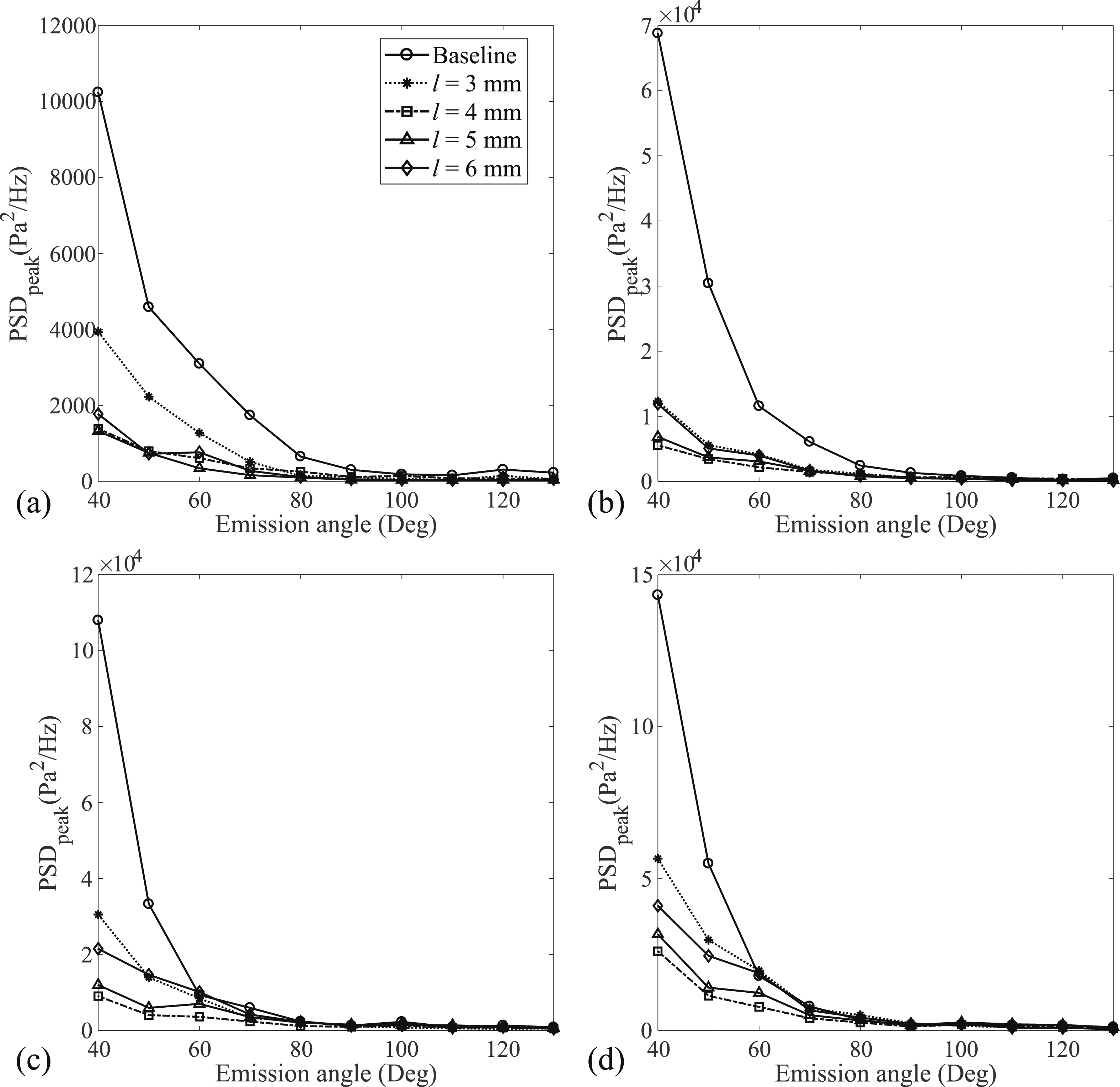
The flow measurements inside the cavity are difficult due to the curvature effect of the pipe-cavity. However, the possible noise attenuation mechanism of cavity noise using a protrusion at the TE is discussed in this section. Figure 14(a) depicts the noise generation mechanism of a cavity without protrusion. The organized, coherent structure and recirculation of the axisymmetric cavity are strongly linked to its natural resonance mode, resulting in strong acoustic tones and intense pressure fluctuations.
10
The separated shear layer emanating from the leading edge of the axisymmetric cavity convects downstream and impinges on the trailing edge, producing strong sound waves that propagate upstream and reach the leading edge. The interaction of acoustic waves subsequently affects the thin, receptive shear layer at the leading edge, generating an unstable, convected shear layer downstream. This process forms a cycle known as a feedback loop, which is responsible for the strong acoustic loading inside the axisymmetric cavity. The feedback loop, a critical aspect of cavity noise, is characterized by the interaction between the convected vortices and the acoustic waves propagating between the leading and trailing edges. This interaction amplifies the oscillations within the cavity, leading to increased SPL and resonance. The feedback occurs as the shear layer, formed at the leading edge, is sensitive to acoustic disturbances generated by the vortices impinging on the trailing edge. This acoustic-shear layer interaction enhances instability in the flow, reinforcing the coherent vortex structures that dominate the noise generation process. The mechanism of mitigation of the cavity noise is illustrated in Figure 14(b) and 14(c), where the trailing edge protrusion reduces the generated noise. The device aims to reduce the feedback mechanism and disturb the recirculation flow of the cavity system. Figure 14(b) illustrates the control strategy of feedback, which disturbs the origination of the coherent vortex structure of the shear layer. The presence of the protrusion produces a reversed flow from the trailing edge, which affects the shear layer at the leading edge of the cavity. The disturbance can also be caused by the increased shear layer thickness at the leading edge due to backflow. Increasing the initial shear layer thickness reduces receptivity and enhances stability.
37
Consequently, acoustic wave generation at the trailing edge and propagation towards the leading edge is disturbed, reducing further enhancement of the leading edge shear layer instability. Additionally, the protrusion acts by breaking the coherence of the recirculating vortices, resulting in a disrupted and less organized flow within the cavity. By interfering with the recirculation, the protrusion prevents the strong vortical structures from forming, which are typically responsible for generating high levels of acoustic radiation. This disruption also alters the flow dynamics in the cavity, particularly by creating secondary flow structures that counteract the primary recirculation. These secondary structures diminish the acoustic resonance by shifting the frequency and intensity of the feedback loop. Moreover, the reverse flow generated by the protrusion creates turbulence and incoherent structures near the trailing edge. This turbulence impedes the propagation of sound waves back to the leading edge, breaking the cyclical nature of the acoustic feedback loop. The thicker shear layer that forms at the leading edge, as a result of this backflow, becomes less susceptible to disturbances from the trailing edge, leading to a more stable flow. Figure 14(c) illustrates the further effect of the protrusion on the radial development of the jet flow inside the cavity. The radial growth of the jet is affected by the obstruction, which disrupts the symmetry and coherence of the recirculating flow. The protrusion blocks the formation of the primary vortex structure that typically dominates the flow in the cavity, resulting in a breakdown of the organized oscillatory pattern responsible for generating tonal noise. This disturbance leads to the formation of a smaller, less coherent vortex structure, which is less capable of sustaining strong acoustic waves. The presence of the protrusion could also lead to increased energy dissipation within the cavity. The disorganized flow creates more turbulent mixing, which in turn increases the viscous dissipation of kinetic energy. This dissipation further weakens the acoustic feedback loop by reducing the energy available for sustaining coherent oscillations, thus contributing to a reduction in noise levels. The protrusion’s primary effect is to destabilize the coherent flow structures within the cavity, disrupting the feedback loop that amplifies cavity resonance. By disturbing both the shear layer and the recirculation zone, the protrusion mitigates the formation of strong acoustic waves, leading to a reduction in overall sound pressure levels and improving the acoustic performance of the cavity system. A schematic of the possible noise generation and attenuation using a trailing edge protrusion is presented. (a) Without the protrusion, a separated shear layer forms a recirculation zone inside the cavity, and an organized, coherent structure is generated, resulting in an acoustic feedback loop, (b) the trailing edge protrusion generates a disorganized and incoherent structure and, due to the reverse flow, the incoming shear layer is more stable than without the protrusion, disrupting the acoustic feedback loop, (c) the radial development of the jet flow is affected by the protrusion, resulting in the disruption of the recirculation zone in the cavity.
Proper Orthogonal Decomposition (POD) analysis
The effectiveness of protrusion in controlling the jet structure is analyzed using the snapshot POD method, which is applied to time-resolved Schlieren images. The inline Schlieren imaging technique is employed to acquire the jet flow images of the controlled system with a protrusion at the TE and the non-controlled pipe-cavity system. Examining the time-resolved Schlieren images provides valuable insights, revealing a correspondence between the image intensity field and the density gradient. Notably, the snapshot POD method yields promising results when applied to both shadowgraph41–43 and Schlieren images.
44
This study performs the POD analysis using the Sirvoch method.
45
The two-dimensional greyscale image intensity field, represented as [i
j
(x, y)], is organized as a matrix Q with the number of grid points and N number of snapshots (j = 1, 2,...N). The reshaped matrix can then be expressed as follows PSD (in arbitrary units) of Baseline and protrusion cases at NPR = 3.0: (a) first mode and (b) second mode.

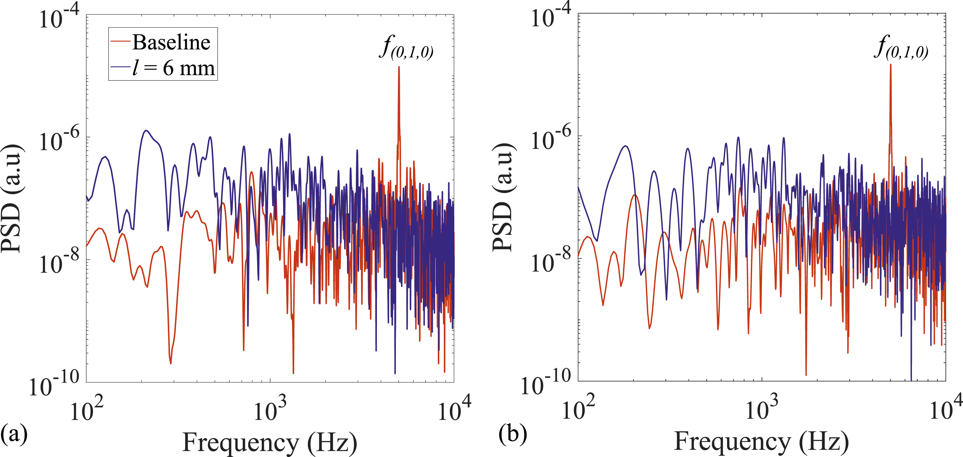
Figure 16 present the first two spatial POD modes for both cases without and with protrusion. The first mode of the baseline pipe-cavity reveals an anti-symmetrical coherent structure in the shear layer region, exhibiting flapping oscillatory motion in the radial direction. This spatial mode is associated with the first tangential mode of the pipe-cavity system, displaying a strong pattern in the range of 1 First (a,c) and second (b,d) POD modes of baseline (a,b) and protrusion (c,d) cases at NPR = 3.0.
Conclusion
A passive control method of cavity protrusions is proposed for the axisymmetric cavity noise control, and the protrusion ring is implemented at the cavity wall. A systematic parametric study investigates the effect of the protrusions on the acoustic characteristics of the pipe-cavity jet. Initially, the effect of protrusions at different locations in the cavity, such as leading edge, trailing edge, and leading and trailing edge cases, are studied. Also, the results are compared with and without a protrusion pipe-cavity system. Further, protrusion length varies from 3 mm to 6 mm at the optimized location. Different acoustic measurement results are presented to understand and characterize the noise reductions. Cavity pressure fluctuations and far-field acoustic pressure are presented in terms of P rms , PSD, and directivity analysis for different flow and geometrical parameters. The findings of this study have potential applications in various industries where axisymmetric cavities are a source of noise and vibration, such as pipelines, aerospace, and power plants. For instance, the reduction of high-amplitude acoustics and vibrations in pipeline systems can help prevent structural damage and reduce maintenance costs.
The pipe-cavity resonates close to the first tangential mode for a wide range of NPRs. Significant noise reduction is observed with the protrusion cases compared to the baseline (without protrusion). However, protrusion at the LE slightly increases the cavity pressure and far-field noise. Among the different protrusion designs, protrusion at the trailing edge effectively attenuates cavity pressure fluctuations and far-field acoustics. This is attributed to the attenuation of the feedback mechanism and the alleviation of the recirculation zone in the cavity. Interestingly, a slight frequency shift is observed for protrusions when compared to without a protrusion case. Power spectra show a higher tonal noise reduction observed at the first harmonic than at the fundamental tone. The 4 mm case shows significant noise reduction for a wide range of NPRs and emission angles in the far-field. However, the maximum noise reduction is observed in the OASPL of about 4 dB with a 6 mm protrusion length case at NPR = 3.0. Furthermore, the effect of cavity protrusion on downstream jet dynamics is being analyzed using the POD technique. A significant reduction in the spatiotemporal oscillation of the jet structure is observed for a protrusion length of 6 mm under NPR = 3.0 conditions.
Footnotes
Declaration of conflicting interests
The author(s) declared no potential conflicts of interest with respect to the research, authorship, and/or publication of this article.
Funding
The author(s) received no financial support for the research, authorship, and/or publication of this article.
