
Abstract
This study experimentally investigates the impact of finlet integration on the aeroacoustic and aerodynamic characteristics of a T-MOTOR 18*6.1 carbon fiber propeller operating at low Reynolds number regimes. Far-field noise and thrust measurements were conducted under static conditions across rotational speeds ranging from 2000 to 6000 RPM and various sound radiation polar angles. Aerodynamic results indicated that finlet integration led to an average thrust performance reduction of 8% across the entire operating range, primarily attributed to increased profile drag. From an aeroacoustic perspective, findings revealed a strong dependency of finlet performance on both propeller rotational speed and noise propagation angle. Notably, finlets at 2000 RPM resulted in broadband noise reduction at high frequencies across all polar angles. Their optimal aeroacoustic performance was observed at lower rotational speeds (2000 RPM) and suction-side polar angles, particularly at 30°, where the broadband noise reduction averaged approximately 6 dB at low frequencies and 3.5 dB at high frequencies. While a tonal noise increase of approx. 1.5 dB occurred at the first blade passing frequency at this speed, the study indicates an influence on flow patterns and pressure fluctuations, inferred from the acoustic and thrust results. However, further optimization of finlet design and selection is essential to expand their beneficial impact across diverse operating conditions.
Introduction
The integration of multirotor electric vertical take-off and landing (eVTOL) vehicles into modern transportation systems has attracted significant and growing attention from researchers and industry stakeholders. These advanced aircraft are currently under development for diverse applications, spanning from unmanned aerial system (UAS)-based parcel delivery services to urban air mobility (UAM) solutions for passenger transportation.1–3 The escalating prevalence of noise pollution has emerged as a critical environmental challenge in urbanized and industrial zones, particularly within airport-adjacent communities.4–7 A growing body of evidence demonstrates that long-lasting noise exposure induces harmful physical and mental health impacts.8–10 This has prompted extensive research efforts to characterize aircraft noise emissions and assess their community-level effects, particularly for populations residing in airport vicinities.11–14 Noise mitigation strategies can be broadly categorized into two main approaches: (1) acoustically optimized vehicle design and (2) operational planning in conventional aircraft. The application and analysis of acoustic-based vehicle design have been widely investigated across various disciplines. 15
Extensive research has been conducted on the mitigation of aerodynamic noise, employing a wide array of passive16–19 and active20,21 noise control methods. These studies aim to reduce unwanted sound emissions, which is crucial for enhancing comfort and environmental compatibility across various aerodynamic systems. The authors’ prior research extensively investigated the impact of passive edge modification methods, such as brush and serration, on wake-leading-edge interaction noise in a tandem airfoil configuration. 19 In that study, surface pressure fluctuations were measured in a subsonic wind tunnel using surface-mounted sensors on the downstream airfoil. The results demonstrated that both brush and serration treatments could mitigate aerodynamic noise, although their effectiveness varied with frequency and the relative positioning of the airfoils. Specifically, the optimal performance for both elements was achieved when the downstream airfoil leading-edge was approximately aligned with the upstream airfoil chord line. These findings provide valuable insights into the mechanisms of wake-leading-edge interaction noise control for practical applications.
Based on conducted studies, the primary sources of aerodynamic noise in propellers are generally categorized into two main types: tonal noise and broadband noise. Tonal noise, which dominates at lower frequencies, originates from the periodic motion of the blades and is concentrated at distinct frequencies (blade passing frequency and its harmonics). Conversely, broadband noise prevails at medium to high frequencies and is considerably more complex than its tonal counterpart. This noise is generated by the presence of turbulent flow, encompassing both atmospheric turbulence and turbulence induced by the propeller itself.
Jacob et al. 22 conducted a numerical investigation to examine propeller sound production using large eddy simulation and acoustic formulations. Their study revealed that while individual blades produce strong tonal sound, the propeller is acoustically compact at low frequencies, leading to destructive tonal interference in the far-field and an overall broadband acoustic signature. They also identified the propeller hub and blade tip vortex shedding as significant sound sources. Posa et al. 23 utilized Large-Eddy Simulation data and the Ffowcs-Williams & Hawkings acoustic analogy to reconstruct the acoustic far field of a hydrofoil-propeller system. Their analysis demonstrated that, with some exceptions at the smallest frequencies, the acoustic far field is dominated by the loading sound coming from the propeller, achieving its highest values of acoustic pressure in the upstream and downstream directions. In contrast, the lowest values occurred on the propeller plane, whose minima were aligned with the spanwise direction of the hydrofoil. A strong dependence on the incidence angle of the hydrofoil was found, although decreasing toward higher frequencies.
In recent years, numerous numerical and experimental studies have extensively investigated various methods for propeller noise reduction. Jiang et al. 24 conducted a comprehensive study on high-efficiency, low-noise propeller designs for UAV applications. Utilizing numerical aeroacoustic simulations and experimental validation, their research demonstrated that modifying geometric parameters, such as increasing chord length and reducing propeller radius, can simultaneously enhance aerodynamic efficiency and effectively reduce broadband noise emissions. Tinney and Sirohi 25 conducted a fundamental study on the sound field generated by multirotor drones in hover. Their research investigated propeller diameters from 8 to 12 inches across various configurations (isolated rotor, quadcopter, and hexacopter), employing a six-degree-of-freedom load cell for aerodynamic performance assessment and a microphone array for near-field acoustic measurements. Key findings revealed correlations between noise generation and the number of rotors, drone rotor size, and aerodynamic performance (thrust). Wei et al. 26 established a numerical model to analyze the aeroacoustic characteristics of toroidal propellers under standard atmospheric conditions. Their study employed transient large-eddy simulation (LES) to compare noise generation mechanisms between toroidal and benchmark propeller designs. In addition to modifications in propeller geometric characteristics, numerous studies have investigated the implementation of trailing-edge serrations as a noise mitigation feature in multirotor systems.27,28 Rong et al. 29 numerically investigated the aeroacoustic characteristics of owl-inspired leading-edge serrated propellers using large-eddy simulations and the Ffowcs Williams–Hawkings acoustic analogy. Their study demonstrated a noise reduction of up to 3 dB with a minor aerodynamic penalty (4–8% in figure-of-merit), achieved by altering vortex shedding dynamics and reducing high-intensity velocity and pressure fluctuations near the blade tips, thereby showing significant potential for quieter propulsion systems.
In the past decade, beyond established methods like leading and trailing edge serrations, the integration of finlets has emerged as a promising tool for noise reduction.30–33 While prior investigations have predominantly focused on evaluating finlet performance on stationary geometries such as airfoils and flat plates, the present study addresses a critical research gap by examining the efficiency of finlets on a propeller geometry, where blade-vortex interaction noise represents a significant and often dominant noise source. For this purpose, this study examines the far-field noise characteristics of a T-MOTOR 18*6.1 carbon fiber propeller at low Reynolds numbers, aiming to assess its sensitivity to propeller rotational speed and sound radiation polar angle. To achieve this, a custom motor and microphone stand were fabricated. Subsequently, far-field noise measurements were conducted under static thrust conditions, systematically covering a range of rotational speeds from 2000 to 6000 RPM (in 1000 RPM increments) and polar angles from 0° to 180° (in 15° increments). Given the varying rotational speeds, the Reynolds number at 75% blade radius (
Experimental set-up
In the present study, specific experimental arrangements were designed and constructed to perform aeroacoustic and aerodynamic measurements of the propeller. All sound measurements were taken at a distance of 3D from the center of the propeller (where D is the propeller diameter), and for polar angles ranging from 0 to 180° in 15-degree increments. The angles of 0°, 90°, and 180° correspond to the direction of the propeller’s suction side, the propeller’s rotation plane, and the direction of the propeller’s slipstream, respectively. This section provides details regarding the components and configuration of the experimental system, including the rotor system (Section 2.1), the aeroacoustic and aerodynamic measurement systems (Section 2.2), the data acquisition system (Section 2.3), surface treatments (finlets) (Section 2.4), and the measurement procedure (Section 2.5).
Rotor system
The propeller used in this research is a carbon fiber T-MOTOR 18*6.1, with a diameter of 18 inches (45.72 cm) and an average pitch of 1.6 inches (4.06 cm). The tests were conducted using the AXI 4120/18 brushless motor, and the rotational speed of the motor was regulated with the Flame 80A electronic speed controller. To supply the necessary voltage to the system, a 22,000 mA six cell battery was used. Finally, the rotational speed of the propeller was measured using the Prolux PX2710 A optical tachometer.
Aeroacoustic and aerodynamic measurement system
To facilitate comprehensive measurements of both noise and thrust generated by the propeller, a comprehensive measurement system was designed, comprising two distinct experimental systems. Each of these systems was independently dedicated to either aeroacoustic or aerodynamic measurements. The overall experimental arrangement, encompassing its separate aeroacoustic and thrust measurement components, is illustrated in Figure 1, where Figure 1(a) depicts the aeroacoustic system and Figure 1(b) shows the thrust measurement system. For aeroacoustic measurements, a dedicated system was designed, including a fixed base for mounting the motor and the propeller, as well as a movable base for installing and repositioning the microphone at various polar angles (from 0 to 180°). Far-field noise measurements were conducted using a RODE NT6 microphone, which features a linear frequency response ranging from 40 Hz to 20 kHz and a maximum measurable sound level of 135 dB. For aerodynamic measurements, a thrust measurement system was utilized to quantify thrust values across different RPMs for both baseline and finlet-equipped propellers. The core component of this system is a 10 kg capacity load cell. Experimental measurement system: (a) Aeroacoustic system; (b) Thrust measurement system.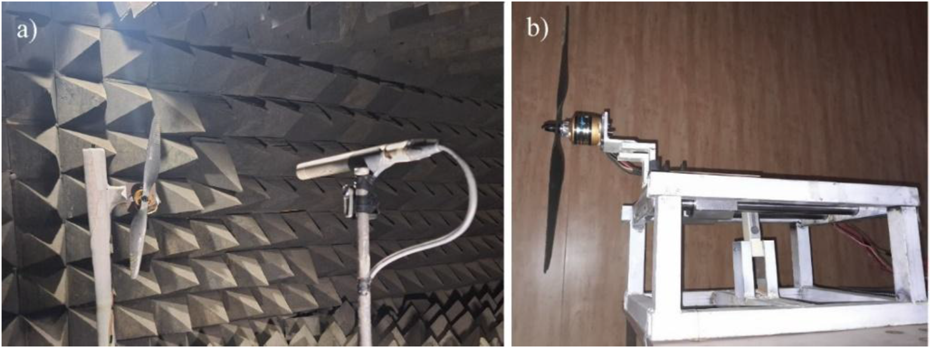
Measurements of noise in the far field were conducted using a RODE NT6 far-field microphone. This microphone has a linear frequency response ranging from 40 Hz to 20 kHz, and the maximum measurable sound level is 135 dB. It should be noted that while the measurements were conducted in a low-noise environment and not a certified anechoic chamber, the reliability of the data for comparative purposes remains high. The setup adhered to far-field conditions and applied strict, repeatable procedures to maintain experimental accuracy. Crucially, the primary focus of this study is the change in the noise spectrum (ΔSPL) between the baseline and finlet-equipped propellers. Since both configurations were measured in the exact same low-noise room and setup, the effects of reflections and constant background interference are considerably minimized and can thus be neglected in the difference spectrum, which supports the validity of the comparative performance evaluation. Figure 2 schematically illustrates the arrangement of microphone positions utilized for aeroacoustic measurements. This setup allowed for noise data acquisition at various polar angles around the propeller. Schematic arrangement of far-field microphone positions for propeller noise measurements.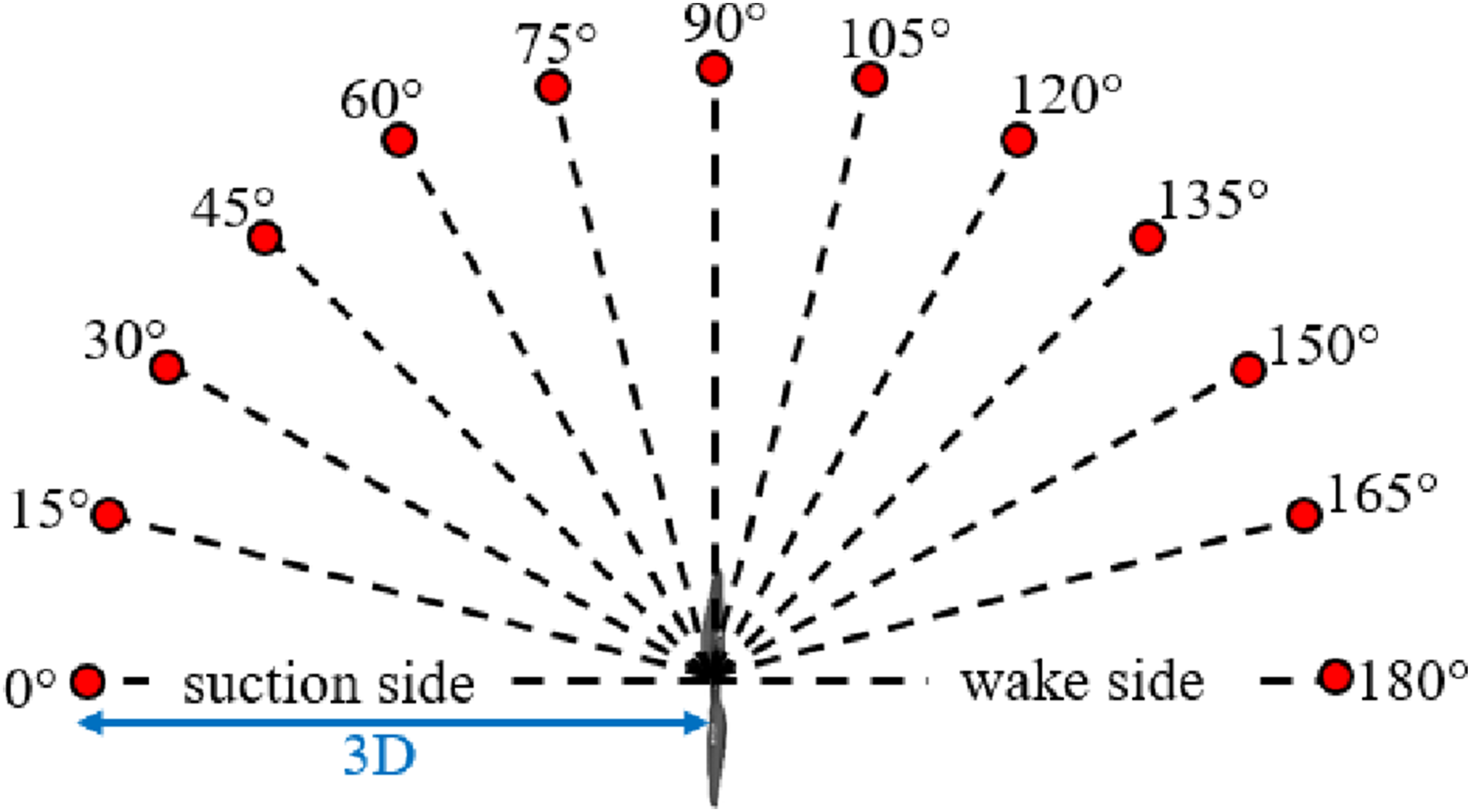
Data acquisition system
In the present study, data acquisition was carried out using the 24-bit Audio Box™ 1818VSL sound card. The sampling frequency for all measurements was set at 64 kHz, and for each measurement, a total of approximately one million data points were recorded over a duration of 16 s. The repeatability of the results was examined for all rotational speeds and positions.
Surface treatments
The present study investigates the impact of utilizing streamwise finlets as a surface treatment on the noise and thrust characteristics of the propeller. Given the significance of noise in regions close to the propeller tip, the finlets were strategically positioned at a spanwise distance ranging from 70 to 100% and at 70% of the chord length from the leading edge. Furthermore, drawing on findings from prior research on finlet performance and boundary layer thickness, the finlet height was established at 2 mm, with a thickness of 0.5 mm and a spacing of 4 mm. The general schematic, design parameters, and installation location of the finlets are presented in Figure 3. Finlet dimensions and installation location on propeller blade.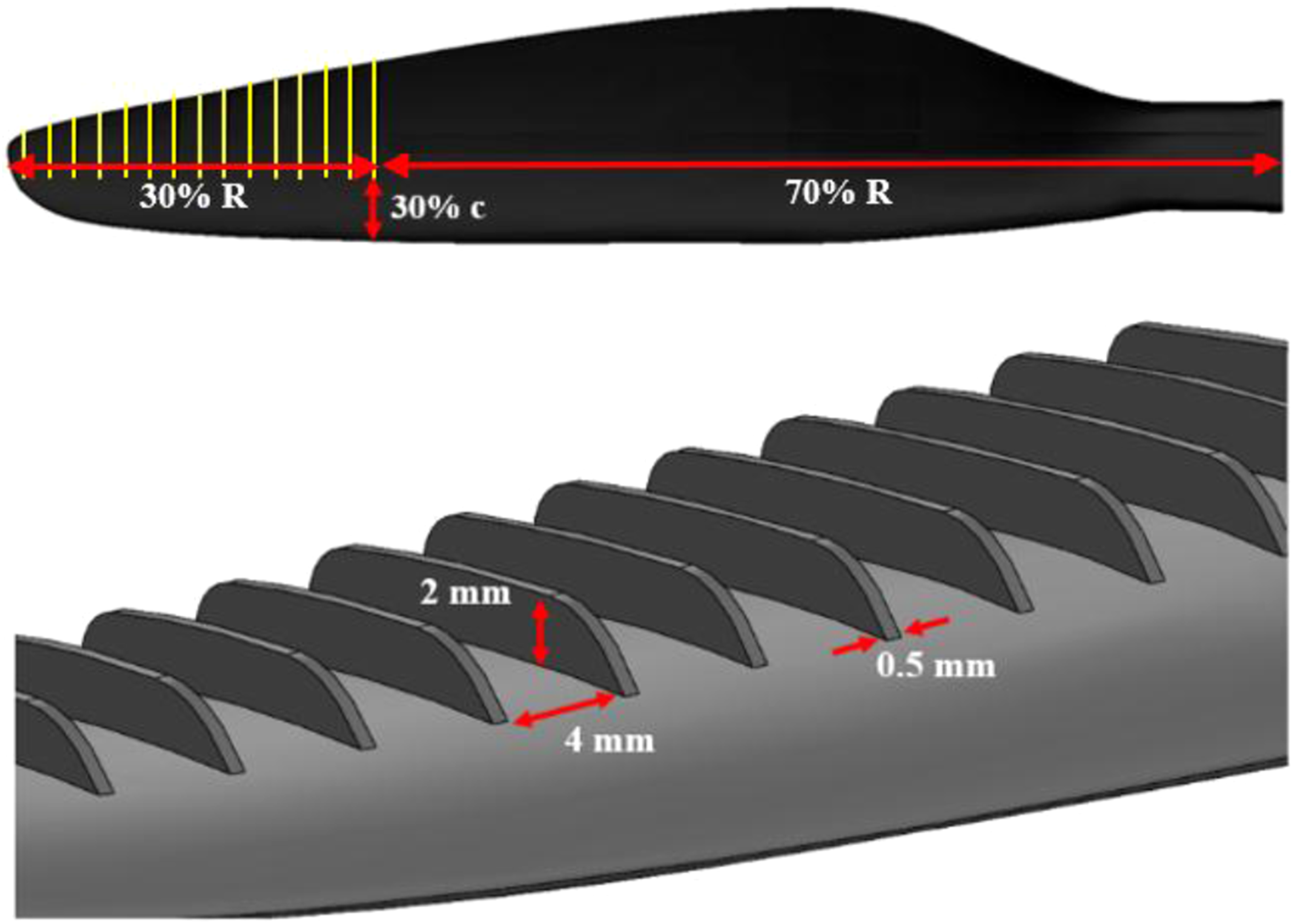
Measurement procedure
In this study, the sound pressure level in decibels was used to investigate propeller noise.


The experimental uncertainty in the pressure PSD of the microphone is primarily caused by statistical convergence error, which is inversely proportional to the number of records used (
Due to the unavailability of an anechoic chamber, the experiments were conducted in a low-noise environment. Consequently, prior to presenting the far-field noise results of the propeller, it is essential to evaluate the signal-to-noise ratio and determine the reliable frequency range. The microphone captures the integrated aerodynamic noise of the propeller, motor, and the background noise. Given the use of the decibel scale, results demonstrate high accuracy in the frequency range where the sound pressure level is at least 10 dB greater than the noise of the unloaded motor and the background noise.36,37
Results and discussion
This section presents the results from the aerodynamic and aeroacoustic measurements for both the baseline propeller and the finlet-integrated propeller at various RPMs.
Aerodynamic results and discussion
Figure 4 illustrates the measured thrust of the baseline propeller versus RPM (represented by the blue line). This figure presents the foundational aerodynamic performance characteristics of the propeller without any finlet integration. As observed, the thrust exhibits an approximately quadratic increase with increasing RPM. This behavior is consistent with fundamental propeller aerodynamic principles, where thrust is proportional to the square of the rotational speed.
38
This baseline data serves as a reference for subsequent comparisons and analyses of finlet integration effects. Validation of baseline propeller thrust measurements across various RPMs against reference data
39
.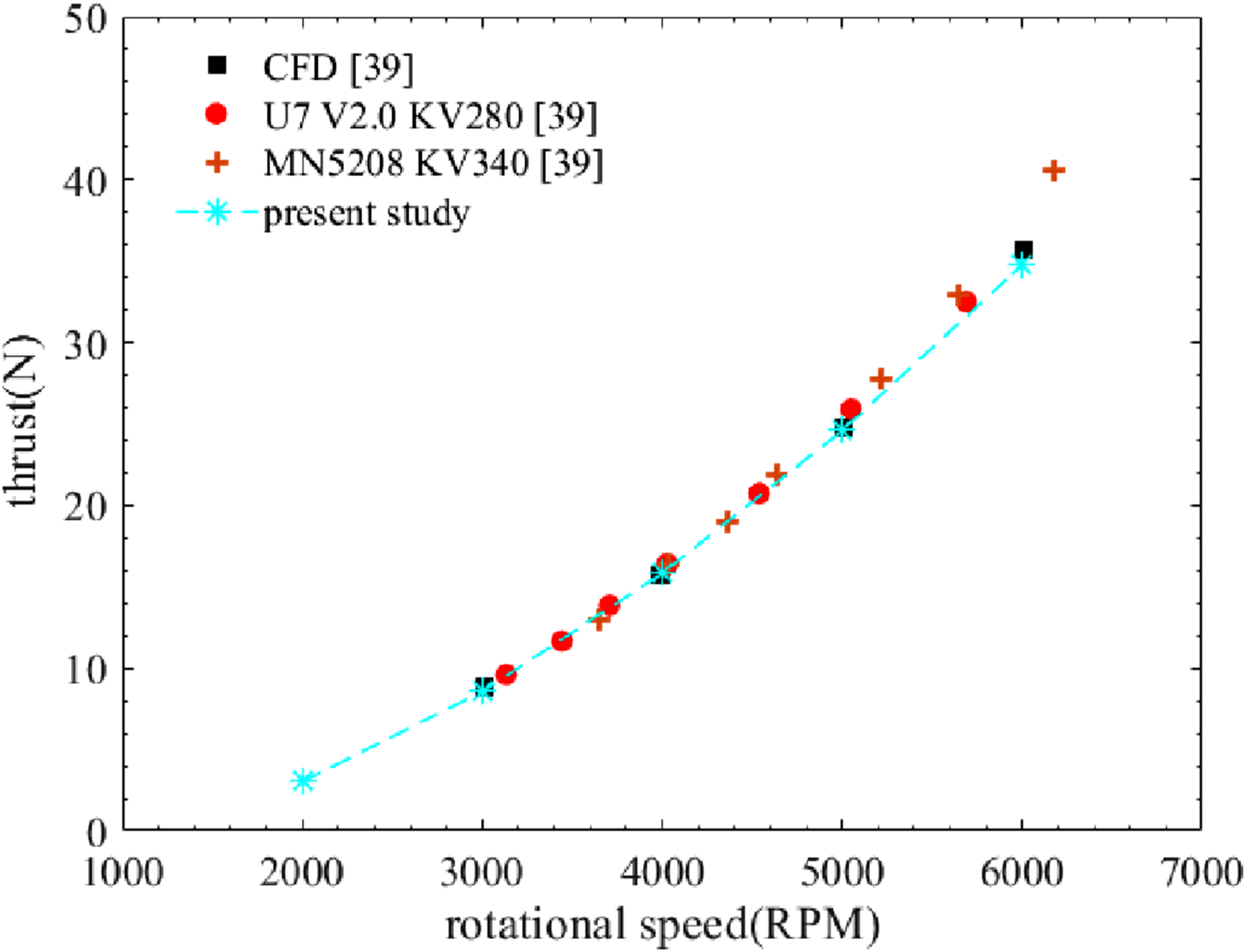
Furthermore, to ensure the accuracy and reliability of the experimental results, the thrust measurement system employed in this study underwent a thorough validation process. The system’s performance was verified by comparing the measured thrust of the baseline propeller across various RPMs with data obtained from. 39 As illustrated in Figure 4, the experimentally obtained thrust values exhibited excellent agreement with the reference data throughout the investigated RPM range. The maximum deviation observed was less than 5%, which falls well within acceptable limits for experimental propeller aerodynamics. This close correlation confirms the precision of our measurement setup, thereby establishing a solid foundation for analyzing the aerodynamic impact of finlet integration.
Figure 5 illustrates the comparative thrust performance of both the baseline propeller and the finlet-integrated propeller across the investigated RPM range. As shown, the thrust for both configurations exhibits a clear, approximately quadratic increase with increasing RPM. From this figure, it is evident that the finlet-integrated propeller generated on average 8% less thrust than the baseline configuration across the entire operating range. This reduction is observed at all RPMs, indicating a general aerodynamic penalty associated with the finlet geometry. This observed decrease in thrust is primarily attributed to the combined effects of two factors, which we have qualitatively quantified based on the finlet geometry and fundamental aerodynamic principles: (1) Dominant Contribution (Profile Drag): The largest portion of this penalty arises from the significant increase in profile drag due to the additional wetted surface area of the finlets. Since the finlets are located in the outer 30% of the blade span (in the tip region), where the local flow velocity is highest, and the drag force scales quadratically with velocity ( (2) Secondary Contribution (Altered Loading): The remainder of this penalty can be attributed to an alteration of the optimal aerodynamic loading distribution of the blade, particularly near the tip where the finlet modifies the pressure field, leading to a reduced local lift-to-drag ratio. Comparison of thrust generated by baseline and finlet-integrated propellers across various RPMs.
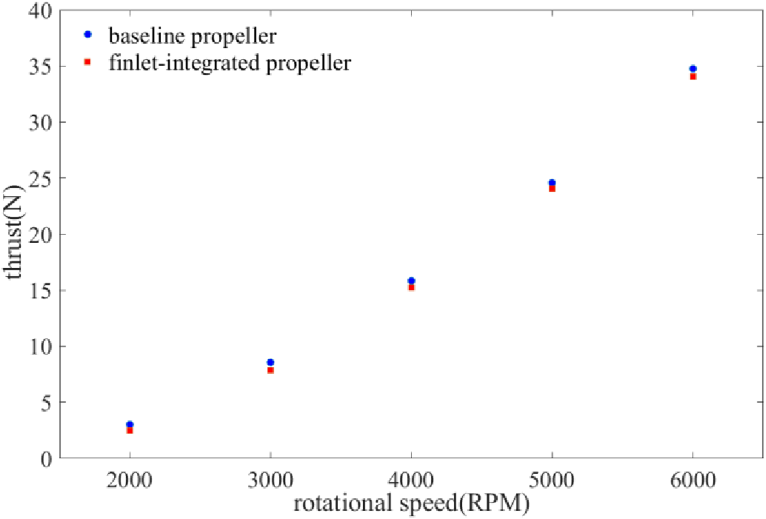
These analyses indicate that the increased profile drag associated with the added geometry is the dominant source of the aerodynamic penalty. These results highlight the inherent trade-off between aerodynamic performance and aeroacoustic benefits when integrating such modifications, a balance that is crucial for propeller design optimization.
Aeroacoustic results and discussion
In the present study, the reliable frequency range was initially determined for all rotational speeds by measuring the background noise and the unloaded motor noise, and subsequently comparing them with the total noise (propeller, unloaded motor, and background noise). Furthermore, to thoroughly examine the structure of the propeller noise spectrum, Figure 6 presents the propeller noise spectrum at a polar angle of 90° and for RPM = 6000, alongside the unloaded motor noise and background noise. As evident from the figure, the unloaded motor noise is high within the frequency range of 1000 to 3000 Hz, which is a common phenomenon in this type of motor testing.
40
Additionally, the first tonal peak of the unloaded motor noise occurs at the motor’s rotational frequency. Therefore, except for the aforementioned frequency range, the signal-to-noise ratio is adequate at other frequencies, and the propeller noise results are reliable. As observed in Figure 6, the propeller noise comprises both discrete tonal noise and broadband noise. Tonal noise typically dominates at low to medium frequencies, stemming from various sources like loading noise, thickness noise, and unsteady blade-vortex interaction noise. Loading noise arises from forces exerted on the fluid by a moving body, whereas thickness noise is generated by the displacement of fluid due to the body’s motion. Previous studies indicate that for speeds well below the speed of sound, thickness noise is less significant compared to other sources, with loading noise being the most dominant contributor to tonal noise. As can be seen from the figure, the largest propeller tonal noise occurs at 200 Hz and its harmonics. This tonal peak corresponds to the first blade passing frequency (BPF) at RPM = 6000 and is calculated using the relationship BPF=(N×RPM)/60, where N is the number of blades and RPM is the rotational speed in revolutions per minute. Conversely, Figure 6 also shows that broadband noise covers a wide frequency range, including high frequencies to which the human ear is sensitive. It’s crucial to note that although broadband noise levels are significantly lower than the tonal noise at the blade passing frequency and its harmonics, its broad frequency coverage accounts for a substantial portion of the total propeller noise energy, making it a critical component of the overall noise generated by the propeller. Noise spectrum of background noise, unloaded motor noise, and total noise at θ = 90∘ and RPM = 6000.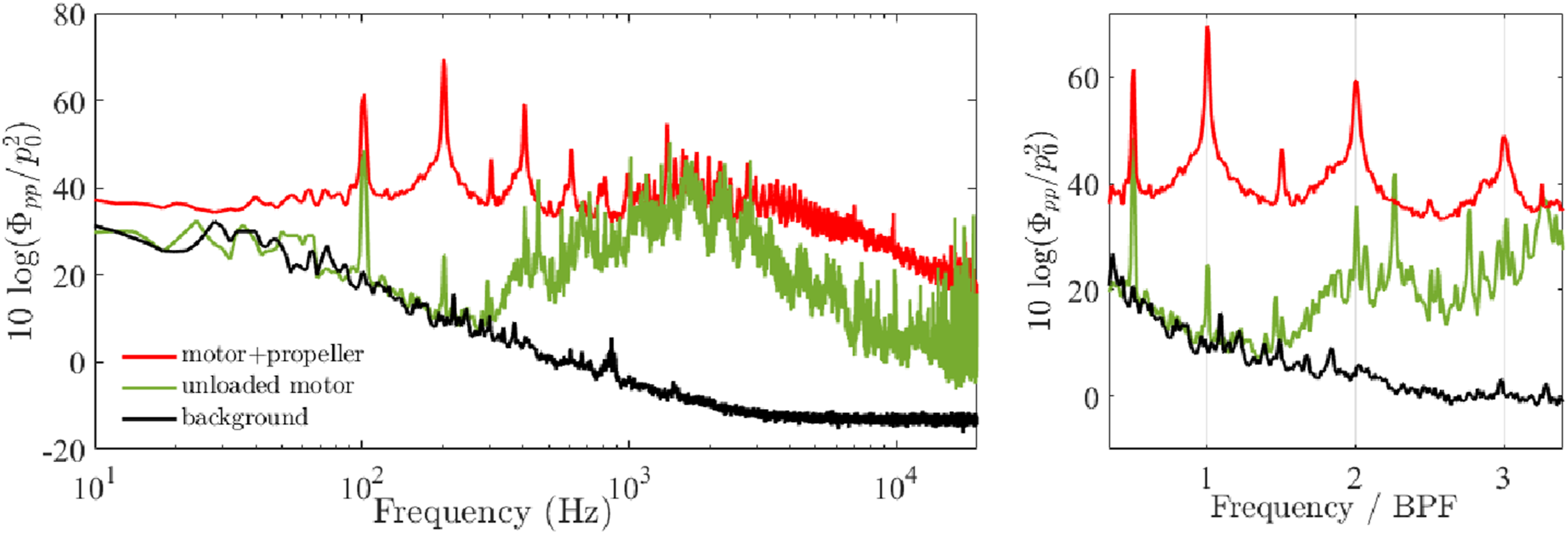
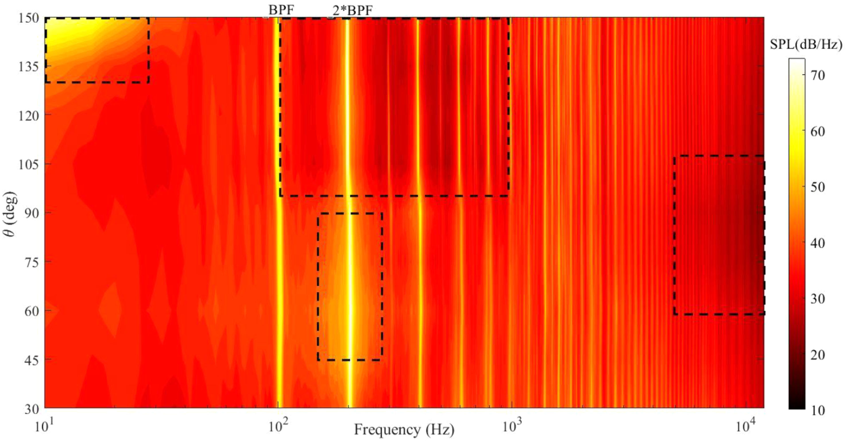
Previous studies have shown that the propeller noise spectrum is a function of the sound propagation direction. The noise spectrum at 6000 RPM is analyzed comprehensively using Figures 7 and 8. In particular, Figure 7 separates the detailed spectra into two main physical regions: (a) the region extending from the Suction Side to the rotation plane (angles 30° to 90°) and (b) the region extending from the rotation plane towards the Wake Side (angles 90° to 150°). Figure 8 then complements this analysis by illustrating the overall angular dependency of the noise spectrum through a contour plot for the same rotational speed. As anticipated, the blade passing frequency remains constant and is independent of the propagation angle. However, two distinct changes are evident in the noise spectrum at polar angles greater than 90° (influenced by the propeller wake): a reduction in broadband noise within the 100 to 1000 Hz range, and a corresponding increase at very low frequencies (below 50 Hz). The increase observed at very low frequencies in the wake region (angles >90°) is likely associated with large-scale flow instabilities and increased unsteady loading as the microphone is positioned in the direction where the highly turbulent wake flow radiates maximum low-frequency acoustic energy. Conversely, at polar angles near the propeller’s rotation plane (60 to 105°), the propeller’s broadband noise levels are significantly lower at frequencies above 5000 Hz compared to other polar angles. This high-frequency noise is primarily generated by self-noise mechanisms, such as turbulent-boundary-layer trailing-edge (TBL-TE) noise, which exhibits a similar behavior in both stationary airfoils and rotating blades. This lower level of high-frequency noise near the rotation plane might be due to the specific directional properties of these self-noise sources, which often exhibit minimal radiation perpendicular to the blade chord.
41
Finally, unlike other polar angles, the propeller noise spectrum shows a gradual increase at the first blade passing frequency (200 Hz) for angles between 45 and 90° (i.e., on the suction side of the propeller). Propeller noise spectrum at various polar angles for RPM = 6000; (a) Results measured in the angular region extending from the Suction Side to the rotation plane (angles 30° to 90°); (b) Results measured in the angular region extending from the rotation plane towards the Wake Side (angles 90° to 150°). Propeller noise spectrum contours at various polar angles for RPM = 6000.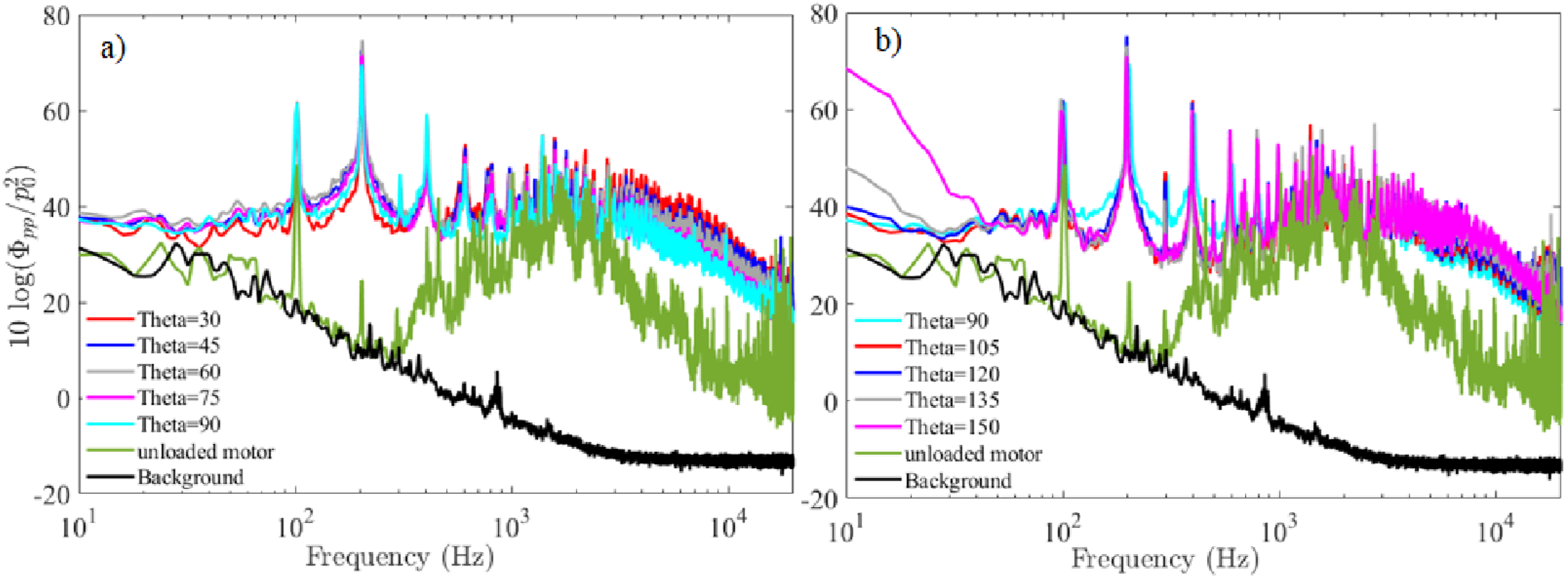
Next, to precisely evaluate the aeroacoustic performance of the finlets, contours of the propeller noise spectrum change resulting from finlet addition are presented in Figure 9 for rotational speeds of 2000, 4000, and 6000 RPM, and at polar angles from 30 to 150°. This figure illustrates the difference between the noise spectrum of the finlet-equipped propeller and the baseline propeller (ΔSPL = SPLFinlet−SPLBaseline). Thus, positive regions indicate an increase in the propeller noise spectrum, while negative regions signify a favorable impact of finlets, resulting in a reduction in the propeller noise spectrum. It should be noted that the term ‘motor contamination’ is used throughout the figures and discussion to denote the frequency region where the noise floor is primarily determined by the inherent noise of the electric motor rather than the propeller’s aeroacoustic emissions. Consequently, changes in propeller noise are considered unreliable or negligible within this contaminated band. As shown in Figure 9(a), for RPM = 2000, finlets lead to a reduction in broadband noise at high frequencies across all polar angles. This high-frequency broadband noise reduction is consistent with the hypothesis that the finlet promotes the early diffusion and breakup of the tip vortex. This breakup reduces the coherence of the vortex structure, thereby lowering the overall broadband noise generation.
42
However, at lower frequencies, the aeroacoustic performance of the finlets is a function of the polar angle. Specifically, finlets result in noise reduction at polar angles on the suction side, particularly at 30° polar angle, while they cause an increase in the noise spectrum at polar angles on the wake side of the propeller. This directional dependence in the lower frequency range suggests that the finlet induces a reorganization of the propeller’s unsteady aerodynamic loading field near the tip. This modification to the load distribution directly alters the acoustic dipole pattern of the loading noise, causing a favorable reduction on the suction side (forward quadrant) and a compensatory increase toward the wake region. Propeller noise spectrum change contours at various polar angles for (a) 2000 RPM; (b) 4000 RPM; and (c) 6000 RPM.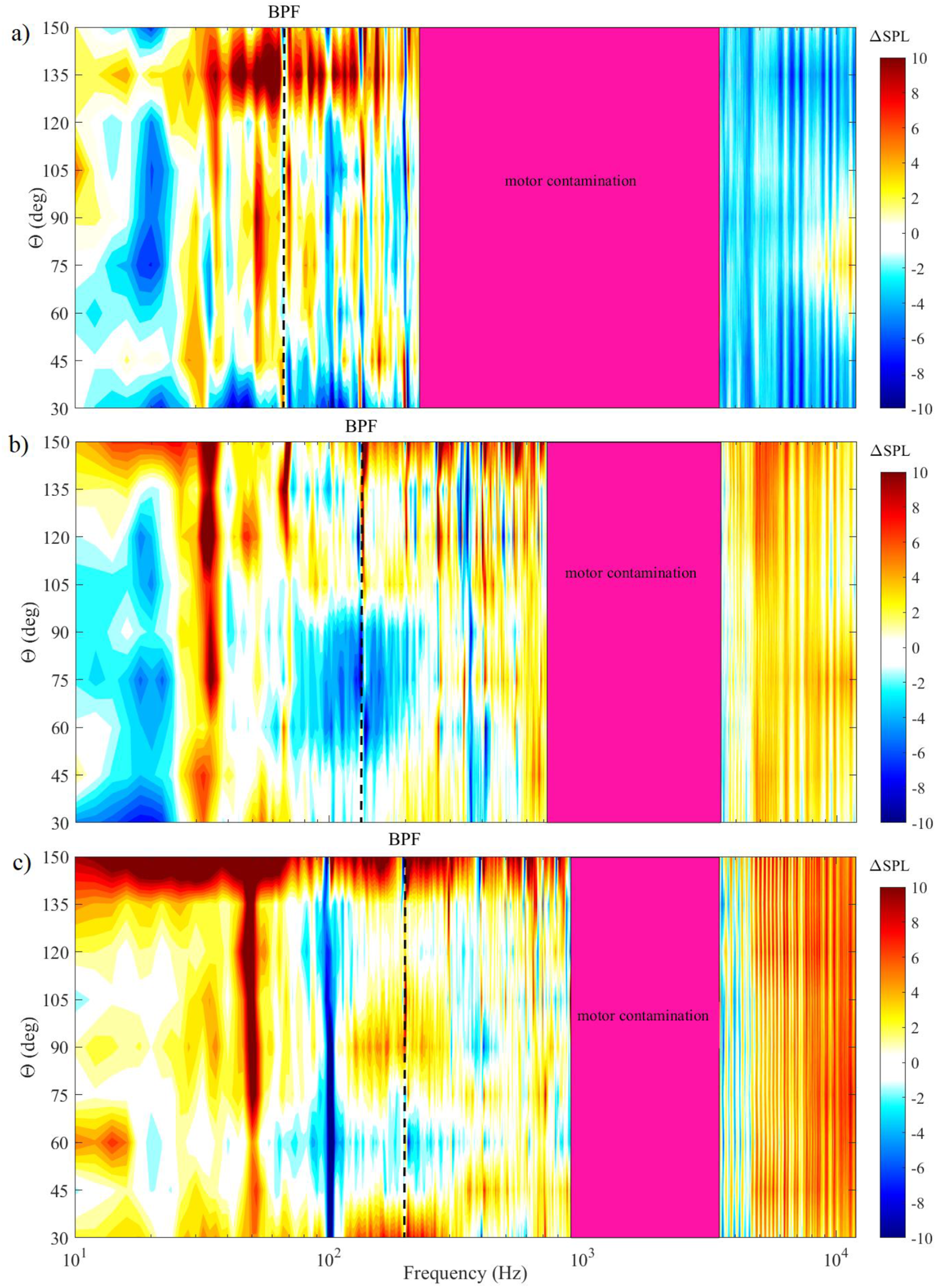
Figure 9(b) reveals that at RPM = 4000, the aeroacoustic performance of the finlets at high frequencies is the inverse of that observed at RPM = 2000. Specifically, at these frequencies, the finlets lead to an excessive increase in the broadband noise spectrum across all polar angles compared to the baseline propeller. This result stems from the competition between two mechanisms: the finlet’s vortex noise reduction effect (similar to 2000 RPM) and the Turbulent Self-Noise generated by the finlet’s new and additional Trailing Edge. Given that trailing edge self-noise scales with a high power of the speed (specifically, the fifth power), this noise is consequently amplified exponentially at this higher speed. 41 This steep increase in the self-noise produced by the finlet structure overwhelms the noise reduction benefit obtained from vortex breakup, ultimately leading to an increase in the overall broadband noise level compared to the baseline propeller (which lacks this additional noise source). However, at lower frequencies, the finlets’ aeroacoustic performance at RPM = 4000 remains a function of the polar angle, similar to RPM = 2000, resulting in noise reduction at polar angles on the suction side. This indicates the relative stability of the acoustic load redistribution mechanism that continues to exert its directional effects on loading noise despite the dominance of self-noise at higher frequencies. Finally, Figure 9(c) shows that at 6000 RPM, the finlets’ aeroacoustic performance is similar to that at RPM = 4000. The key differences are a more severe increase in broadband noise at high frequencies and a smaller noise reduction at low frequencies. Overall, finlets cause an increase in propeller noise across most polar angles at this speed. A notable increase in broadband noise at mid and low frequencies is observed with increasing RPM, particularly at angles near 150° (i.e., in the propeller wake region). Therefore, the results generally indicate that finlets exhibit their best aeroacoustic performance at lower rotational speeds and at polar angles on the suction side.
To quantitatively evaluate the aeroacoustic performance of the finlets in the desired suction side region, the propeller noise spectrum at a polar angle of 30° is presented in Figure 10 for rotational speeds of 2000, 4000, and 6000 RPM. To distinguish between the aerodynamic noise of the propeller and the motor noise, the noise spectra of the unloaded motor (measured in isolation) are also superimposed for each rotational speed. As the figure shows, the frequency bands previously identified as ‘motor contamination’ regions coincide with the recorded noise spectra of the motor without the propeller. This observation justifies the exclusion of these specific frequency ranges from the aeroacoustic analysis, ensuring that the primary conclusions are based on the verified reliable frequency range. As the figure clearly shows, the finlets’ performance in reducing noise is highly dependent on the propeller’s rotational speed. Comparison of propeller noise spectrum for baseline and finlet-equipped propellers at θ = 30∘ for 2000, 4000, and 6000 RPM, including the unloaded motor noise.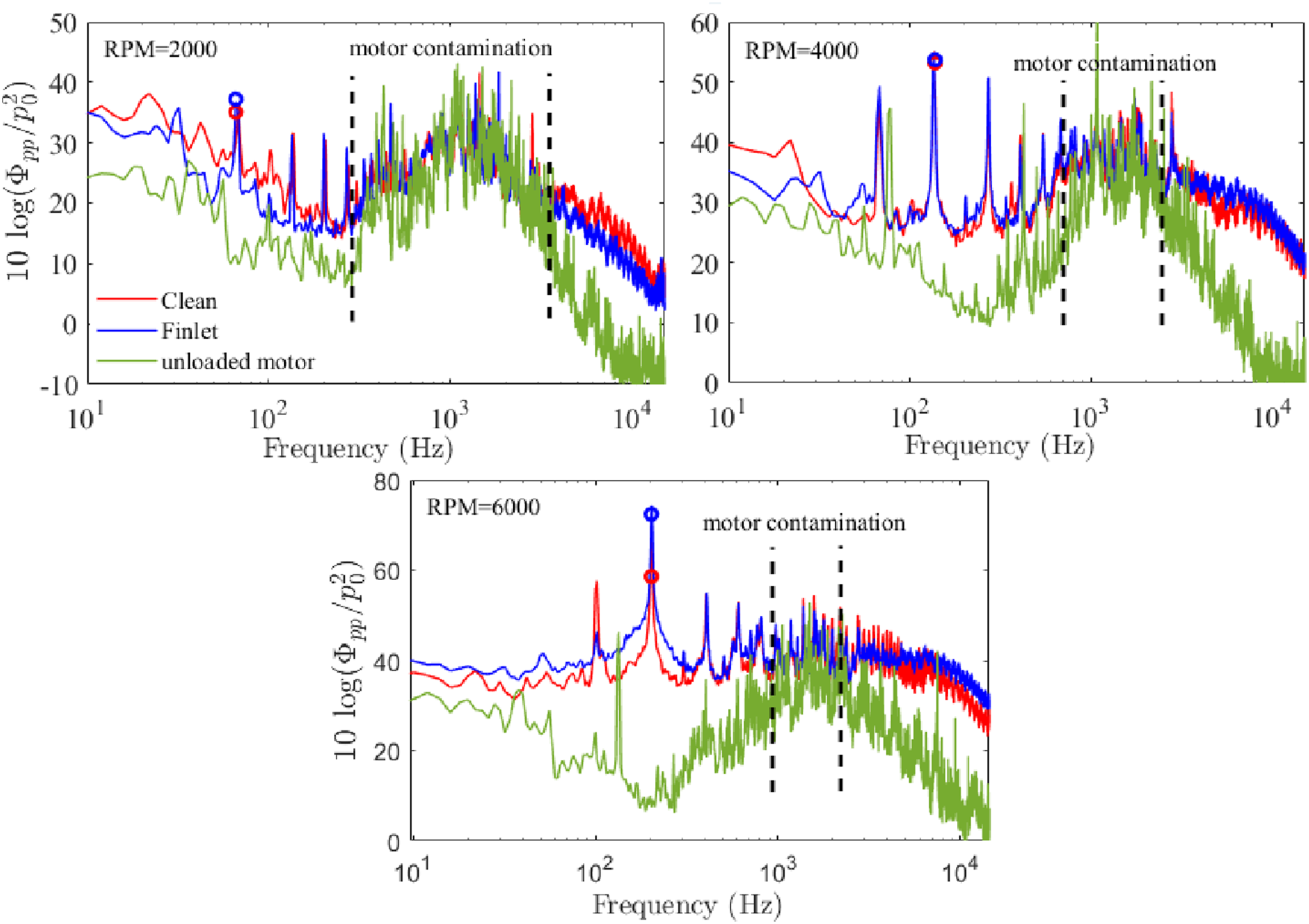
At 2000 RPM, the finlet demonstrates optimal performance. The propeller’s broadband noise is reduced across the entire reliable frequency range, with this reduction averaging approximately 6 dB at low frequencies and 3.5 dB at high frequencies. This reduction indicates the dominance of the positive mechanism of tip vortex breakup and acoustic load redistribution. 42 However, the tonal noise at the first blade passing frequency (BPF) experiences a relatively marginal increase of approximately 1.5 dB. This tonal increase, which stems from unsteady force fluctuations at the blade tip, suggests that the finlet geometry has increased the blade’s sensitivity to inflow disturbances (e.g., system wakes), leading to tonal noise production at this low frequency. Conversely, at 4000 RPM, the balance shifts toward negative mechanisms. The broadband noise increases at high frequencies, which is entirely consistent with the justification provided for Figure 9(b): at this speed, the finlet’s Trailing Edge Self-Noise mechanism has dominated over the positive effects of vortex breakup. Nevertheless, noise reduction is maintained only at very low frequencies (stemming from the stabilized load redistribution mechanism). Notably, the tonal noise remains nearly unchanged at this speed, which could be due to a mutual cancellation between the tonal effects caused by the finlet’s increased unsteady loading and overall changes in the tip flow.
Finally, at 6000 RPM, the negative impacts reach their maximum, and the finlets lead to an increase in propeller noise across almost the entire reliable frequency range. This severe dominance of broadband noise is clearly caused by the immense intensification of the Trailing Edge Self-Noise (as discussed in Figure 9 justification for high speeds 41 ). Furthermore, the tonal noise also increases significantly, by approximately 8 dB. This sharp increase in tonal noise (BPF) confirms that with the intensification of turbulent interactions and the increased speed of the blade passing through inflow disturbances, the finlet structure has severely exacerbated the blade’s dynamic response to inflow disturbances, pushing the unsteady force fluctuation production to a critical level.
Conclusions
This study presented a comprehensive experimental investigation into the impact of finlet integration on the aeroacoustic and aerodynamic characteristics of a T-MOTOR 18*6.1 carbon fiber drone propeller operating at low Reynolds number regimes. Detailed measurements of thrust and far-field noise spectra were conducted under various operational conditions, including rotational speeds ranging from 2000 to 6000 RPM and different sound radiation angles. Aerodynamic results revealed that finlet integration led to an average reduction of 8% in thrust production across the operating range. This reduction was primarily attributed to the substantial increase in profile drag due to the finlets’ additional wetted surface area (exacerbated by the high velocity at the outer span, scaling quadratically with speed), with an alteration in the blade’s aerodynamic loading distribution contributing secondarily. From an aeroacoustic perspective, it was found that the finlets’ noise reduction performance is highly dependent on both the propeller’s rotational speed and the noise propagation angle. At lower rotational speeds (2000 RPM), finlets resulted in broadband noise reduction at high frequencies across all polar angles. This effect is physically attributed to the finlet’s promotion of early tip vortex diffusion and breakup, leading to a reduction in vortex coherence and lower broadband noise generation. Furthermore, the most favorable aeroacoustic performance was observed at the suction-side polar angles, particularly at 30°, where the broadband noise reduction averaged approximately 6 dB at low frequencies and 3.5 dB at high frequencies. However, the tonal noise at the first blade passing frequency increased by approximately 1.5 dB. At higher RPMs (4000 and 6000 RPM), the positive impact of finlets was more limited, and propeller noise increased in most regions. This failure is attributed to the Turbulent Self-Noise generated by the finlet’s additional Trailing Edge. Since this self-noise scales steeply with speed (specifically with the fifth power), it is exponentially amplified at high RPMs, overwhelming the noise reduction benefits and leading to the overall increase in broadband noise. This broadband noise increase was particularly notable at mid and low frequencies and at angles near the propeller wake region (150°). Overall, these findings suggest the finlets’ potential to modify flow patterns and pressure fluctuations, as inferred from the acoustic and thrust measurements, a prerequisite for noise control. Nevertheless, the results highlight inherent challenges in passive noise control design, where a single solution is not necessarily optimal across all operating conditions. To expand the range of desirable finlet effects and minimize aerodynamic penalties, future research should focus on the meticulous optimization of finlet design, placement, and dimensions to achieve an optimal balance between aerodynamic and aeroacoustic performance across diverse flight regimes.
Footnotes
Acknowledgments
Authors would like to acknowledge the aeroacoustics research team at the University of Bristol for their invaluable scientific support.
Funding
The authors received no financial support for the research, authorship, and/or publication of this article.
Declaration of conflicting interests
The authors declared no potential conflicts of interest with respect to the research, authorship, and/or publication of this article.
Data Availability Statement
The data that support the findings of this study are available from the corresponding author upon reasonable request.