
Abstract
This study investigates a novel self-sensing approach for monitoring the structural health of concrete structures by developing hybrid textile-fiber-reinforced concrete (TFRC) elements. The proposed concept offers to use carbon-based textile positioned within electrically conductive concrete medium, functioning both as the primary reinforcement system and as a sensory device for the concrete body. By exploring changes in the impedance spectrum and characterizing the equivalent electrical circuit, measurements of the electrical resistance (R) and capacitance (C) of the concrete are achieved. Both electrical properties are used as indicators for assessing the structural health by two transverse gauge-factors, namely
Keywords
Introduction
Cementitious matrices are characterized by electrical properties enabling the development of multifunctional smart self-sensory concrete elements.1–6 To enhance the piezoresistive properties of the concrete, conductive admixtures, usually based on carbon, were added to the matrix. Various configurations of carbon were investigated, among them: dispersed carbon fibers (CFs),7–11 carbon black,12,13 carbon nanofibers, 14 carbon nanotubes,15,16 and graphene.17,18 Most of the studies focused on the capabilities to correlate changes in electrical properties to strain and damage under compressive loads1,3,14,15,19,20 or flexural loadings.2,13,21 Since no additional reinforcement system was applied, the investigations focused on the healthy stage and terminated when cracks were formed. The electrical connections in these studies involved additional external or internal devices, separated from the load bearing system, such as copper wires, strips, and plates. To overcome these limitations and to further enhance both structural and monitoring capabilities of the concrete elements, the current study offers to combine fiber-reinforced concrete (FRC) and textile-reinforced concrete (TRC) technologies for the development of new age intelligent hybrid textile-fiber-reinforced concrete (TFRC) elements. The proposed new concept offers to utilize the electrical conductivity of the carbon yarns to be used as internal smart-sensory devices that monitor changes in the electrical properties of the concrete medium. The goal of this study is to demonstrate and prove the new concept.
The use of CFs as an additive to concrete mixtures has been investigated in the literature to enhance mechanical properties, such as flexural strength, ductility, crack control, and piezoresistive properties,22–24 leading to smart and efficient structural elements with self-sensing capabilities. The improved structural response is attributed to the advanced mechanical properties of the CFs, according to the rule of mixture, and to the enhanced post-cracking behavior resulting from the crack bridging mechanism.22–27 The sensory capabilities are enabled by the electrical conductivity of the CFs. It is highly dependent on the percolation phenomenon, which is defined as the volume fraction of fibers at which adjacent fibers come into contact, forming a continuous electrical path. When CF content exceeds the percolation threshold, the electrical conductivity of the concrete increases significantly. In such cases the elements exhibit good and consistent piezoresistive behavior.7–11
Investigations of the self-sensory capabilities of concrete elements have explored changes in either resistivity or capacitance, depending on the electrical setup. Each property offers distinct advantages, challenges, and varying levels of convenience in implementation. In the present study, the proposed SHM method, based on impedance spectrum measurements, enables simultaneous monitoring of electrical resistance and capacitance without the need for external devices.
Electrical resistance measurement is relatively simple to implement, but it requires the material to exhibit significant piezoresistive properties. Measurements are often performed using external electrodes and are prone to effects such as contact resistance and polarization.14,15 Common electrical setups to explore changes in electrical resistivity of concrete were based on 2-probe and 4-probe methods using DC measurements,2,3,7,10,11,15,19,22 or AC setups with a predefined electrical current frequency focusing on the resistive component of the impedance.8,9 The studies reported that the electrical resistance decreases upon compressive loads, and since the elements were investigated in their healthy stage, the changes were reversible. Therefore, the concept of gauge factors (GFs) was adopted to correlate between the mechanical strain and the measured resistance change.3,13,14
In the case of electrical capacitance,28–35 more complex and expensive instrumentation is required. Measurements of the concrete for self-sensory purposes are typically based on the use of external electrodes or conductive films,28–33 along with the need for higher measurement frequencies. The focus was on the relative permittivity (dielectric constant of the material) which serves as the sensing parameter. Different electrical setups were reported, such as parallel-plate capacitor configuration, in which the concrete body is located between two metal plates28,34 or coplanar electrodes.30,31 In such cases the piezo-permittivity was investigated, referring to the correlation between the capacitance and the applied stress or strain.30,32 It was shown that the addition of short CFs increases the relative permittivity of the matrix 28 and as a result the monitoring capabilities. Since the measurements were based on external devices, separated from the structural system, careful considerations were given during the installation process to prevent damage to the load bearing system.
To allow continuous self-monitoring capabilities, also at advanced damage scenarios, and to eliminate the need for external connections, the current study offers to merge the technologies of TRC and FRC. The high load-carrying capacity and superior corrosion resistance of the textile enable significant reduction in cross-sectional thickness and accordingly the construction of thin-walled concrete elements with enhanced structural performance.36–41 By using carbon yarns and utilizing their electrical properties, multifunctional structural elements with integrated self-monitoring capabilities were achieved.42–50 Demonstration of the self-sensory concept has been investigated to monitor the structural stage,43,45 detect cracking, strain,44,45,48 and its location 50 in laboratory-scale elements. In such cases, the measurements were based on exploring changes in electrical properties of the yarn itself and not of the concrete body. Moreover, advanced measurements were observed in cases where the matrix was electrically insulated.
The current study focuses on a new sensing concept utilizing carbon-based textiles as smart and integrated internal sensory devices to measure changes in electrical properties of the concrete body. The hypothesis of the study argues that by developing a designated electrical setup, the measured electrical changes of carbon-based textile can monitor mechanical properties of the concrete medium. The proposed hybrid TFRC elements offer several advantages over smart FRC elements including the following: no need for external sensory devices; a simple production process; and, above all, the ability to continuously monitor structural health under extensive cracking and damage scenarios.
The study presents a proof of concept on small-scale laboratory experimental setup. However, performing impedance measurements in field conditions is challenging and requires careful consideration, particularly, challenges that are associated with the transitions to continuous measurements of full-scale structural elements using electrical impedance spectroscopy. These challenges also include varying environmental conditions, which may necessitate dedicated compensation systems or algorithms, particularly to account for the effects of temperature and humidity on electrical impedance. 51 Additionally, there is a need for reliable and cost-effective measurement instrumentation capable of continuous data acquisition, which may require the use of systems operating over a limited frequency range or at a single optimized frequency.52,53 Such investigations, involving large-scale elements and field validation, are beyond the scope of this paper and are left for future research.
The investigation is divided into three main parts. In the section “Sensory concept,” the sensory concept of hybrid TFRC beams is presented. In the section “Materials and methods,” characterization of the mechanical and electrical properties of conductive concrete mixtures with varying fiber contents is performed. It also gives details about the production process and loading setup of the hybrid elements. In the section “Results and discussion,” hybrid TFRC beams are investigated under incremental step loadings and cyclic loadings, aiming to explore structural-electrical correlations and demonstrate the monitoring capabilities for SHM purposes. The paper ends with summary and conclusions in the final section.
Sensory concept
The hypothesis of the study argues that using electrically conductive carbon yarns as smart sensory devices enables measuring changes in the electrical properties of the matrix that are correlated to its structural health. The advantages of the proposed system are that there is no need for additional external or internal sensory devices such as copper plates, electrodes, and wires.7–11,15–21 As a result, the production of elements is performed by a simple process that doesn’t require special modifications or costs. The proposed concept can be easily realized for various types of matrices and electrically conductive mediums. The current study proves its capabilities with an electrically conductive matrix composed of Portland cement (PC) reinforced by dispersed CFs.
The proposed smart self-sensing system is composed of a concrete body and a textile component, each with its own electrical characterization. Generally, a concrete body is characterized by its electrical resistivity and capacitance,8,9 whose values depend on the electrical conductivity and properties of the material.7–11,28–32 Each carbon yarn is characterized by an electrical resistor (R) and inductor (L) that are serially connected, that is RL electrical circuit. 51 The global electrical circuit depends on the relative positioning of the carbon yarns with respect to potential crack and damage. In the proposed smart structural system, the carbon yarns are used as the main reinforcement system. Therefore, they are positioned along the element in the direction of the tensile stress, perpendicular to potential cracks.
The study measures the electrical changes in the concrete body by two parallel carbon yarns that are connected by one of their ends to the data acquisition (DAQ) system. Therefore, the electrical circuit is linked by the electrically conductive matrix. Figure 1(a) schematically describes the characterization of the electrical system. Since the yarns are not connected at both ends, the measured electrical changes are governed by the electrical properties of the medium between them rather than by the properties of the yarns themselves. Note that the proposed setup is completely different than the electrical setup of smart carbon-based TRC elements, in which the electrical signals were solely associated with changes in the carbon yarns since both ends were connected to the DAQ system.42–50 Consequently, in our case, an electrical model of resistors and capacitors connected in parallel can be used to represent the equivalent electrical properties of the medium between the yarns. Electrical modeling ofthe concrete body by a parallel RC electrical circuit is commonly used in the literature8,9 and will be further verified in the current study. The hypothesis of the study argues that changes in R and C are affected by straining and cracking of the matrix. When the concrete matrix is uncracked, the stress is carried by the matrix and the CFs; see Figure 1(b). Accordingly, the electrical changes are governed by strain and geometrical changes in the concrete medium. When micro-cracks are formed, the tensile stress is carried by both the carbon yarns and the CFs that bridge over the cracks surface; see Figure 1(c). Since cracks disrupt the continuity of the matrix, significant changes in electrical properties of the hybrid element are expected.
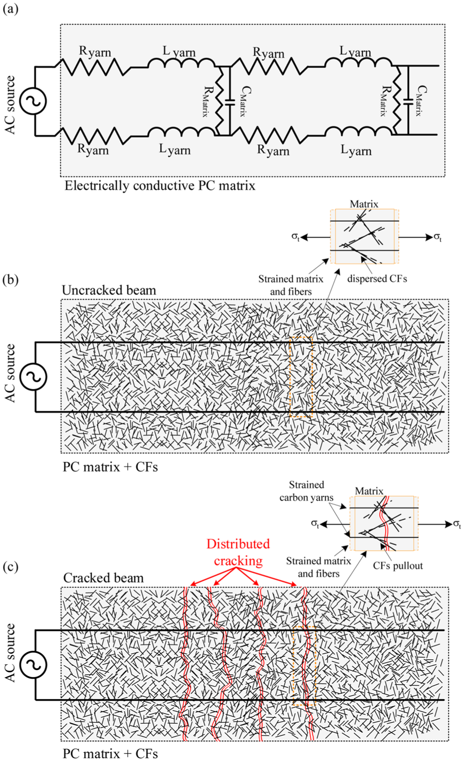
Hybrid TFRC beam mechanical-electrical mechanism: (a) Schematic electrical layout, (b) Uncracked element, and (c) Cracked element.
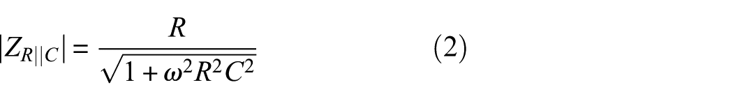
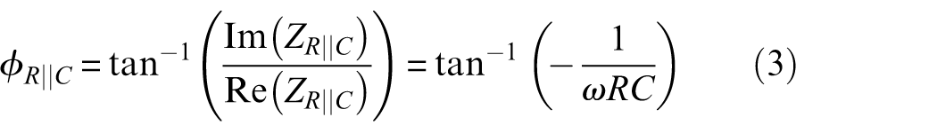
In the case of the parallel RC electrical circuit, the electrical impedance and phase angle can be calculated as follows:
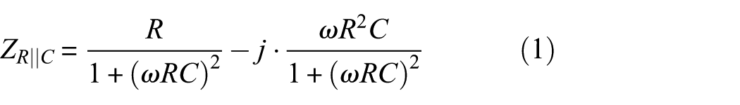
where
By measuring the response spectrum of the impedance in a specified frequency range, the resistance and capacitance that characterize the concrete body can be estimated. In our case, the measurements are taken by anLCR analyzer (Keysight E4990A-010). The measurement range includes 400 different frequencies between 20 Hz (lowest) and 1.5 MHz (highest). At relatively low frequencies, the impedance is relatively high and is governed by the resistive part. At high frequencies the impedance is reduced and dominated by the capacitive part. Therefore, focusing on a middle range of frequencies (370–560 kHz corresponding to 50 different frequencies) aims to provide information on changes in both electrical properties. From a sensing perspective, the dual measurement provides higher convenience compared to previous studies that focused on single electrical property, since it allows to verify the results and distinguish between structural stages.
The measurements of the response spectrum of the impedance are taken continuously during the loading process, every 2.3 s (measurement frequency of 0.43 Hz). For each measured response spectrum, a post-process procedure based on a nonlinear least squares minimization method is used to best fit R and C to the theoretical model. The goal is to minimize the error between the model’s impedance,
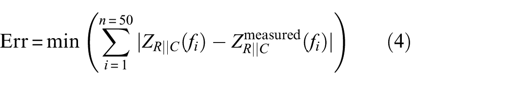
The fitting process is performed with the commercial software MATLAB, by using “fit” function with “Non-Linear-Least-Squares” method and “Trust-Region” algorithm.
In order to quantitively correlate changes in the electrical properties of the matrix with its structural health, the study offers to adopt the concept of GF. GF is defined as the relation between the relative change in electrical property and the mechanical strain, commonly measured in parallel directions. In our case, the carbon yarns are positioned perpendicular to potential cracks. It means that the electrical measurement and the mechanical effect are perpendicular to each other. Accordingly, these correlations are considered as transverse GFs compared to the common case of longitudinal GFs. Applying strain in one direction and measuring electrical resistance change in the transverse direction was reported in Wen and Chung. 54
The current study offers two different transverse GFs (
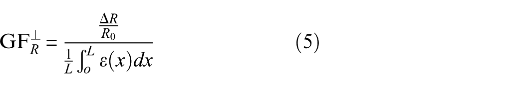
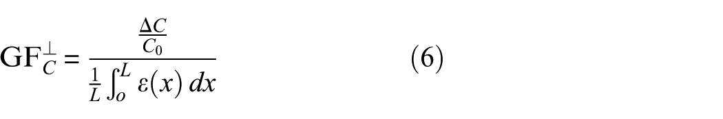
where R0 and C0 are the initial values of resistance and capacitance of the matrix, L is the length of the specimen in the tensile direction, and
Materials and methods
The smart hybrid TFRC beams are composed of a PC matrix that is reinforced by additive short CFs and a carbon-based textile. The section characterizes the mechanical and electrical properties of the matrix and the carbon-based textile. The section also presents the production process of the beams, the loading setups and procedures used in the experimental investigation.
Smart conductive cementitious matrix
The mechanical and electrical properties of the cementitious mixtures are affected by the volume fraction of the CFs. This section investigates the optimal fiber content according to both properties.
Production of PC matrix with additive CFs
The study uses a high-strength and fine-grained PC mixture 55 that is reinforced with additive short CFs. The components and quantities of the concrete mixture are summarized in Table 1.
Components and quantities of concrete mixture.
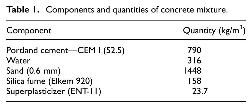
The CFs are a product of Teijin company Ltd and its commercial name is Tenax-A HT C124. The CFs are chopped yarns with a length of 3 mm. The properties of the fibers, according to the producer, are as follows: filament diameter 7 μm, density 1.77 g/cm3, tensile strength 4100 MPa, tensile modulus of elasticity 240 GPa, and elongation at break 1.7%. The CFs were mixed with water and then added to the dry materials. The mixing process was performed with a commercial mixer (model Hobart C-100). The components were gradually added into the mixer. The entire mixing procedure lasted approximately 16 min.
The specimens were cured within the molds for 48 h in a room temperature of 22°C–23°C. The dimensions of the molds are specified according to the relevant investigation, given in the next sections. Then, the specimens were demolded and cured in lime-saturated water for 28 days.
The study explores eight different volume fractions (V f ) of CFs: 0% (plain concrete matrix), 0.1%, 0.3%, 0.4%, 0.5%, 0.6%, 0.9%, and 1.2%. The volume fraction is calculated with respect to the mass of the cement in the mixture.
Production of specimens for mechanical and electrical characterizations
Two types of specimens are used for the preliminary mechanical and electrical investigations: 40/40/160 mm beams and 50/50/50 mm cubes. The specimens’ dimensions are in accordance with EN 196-1:2005. 56 For each volume fraction of CFs, three cubes are cast for the compressive strength tests, three beams for strength tests, and three beams for electrical characterization. The electrical measurements were performed by embedding two copper plates within the beams during the casting process. The copper plates are used as probes, and positioned in distances of 40, 80, and 120 mm; see Figure 2.
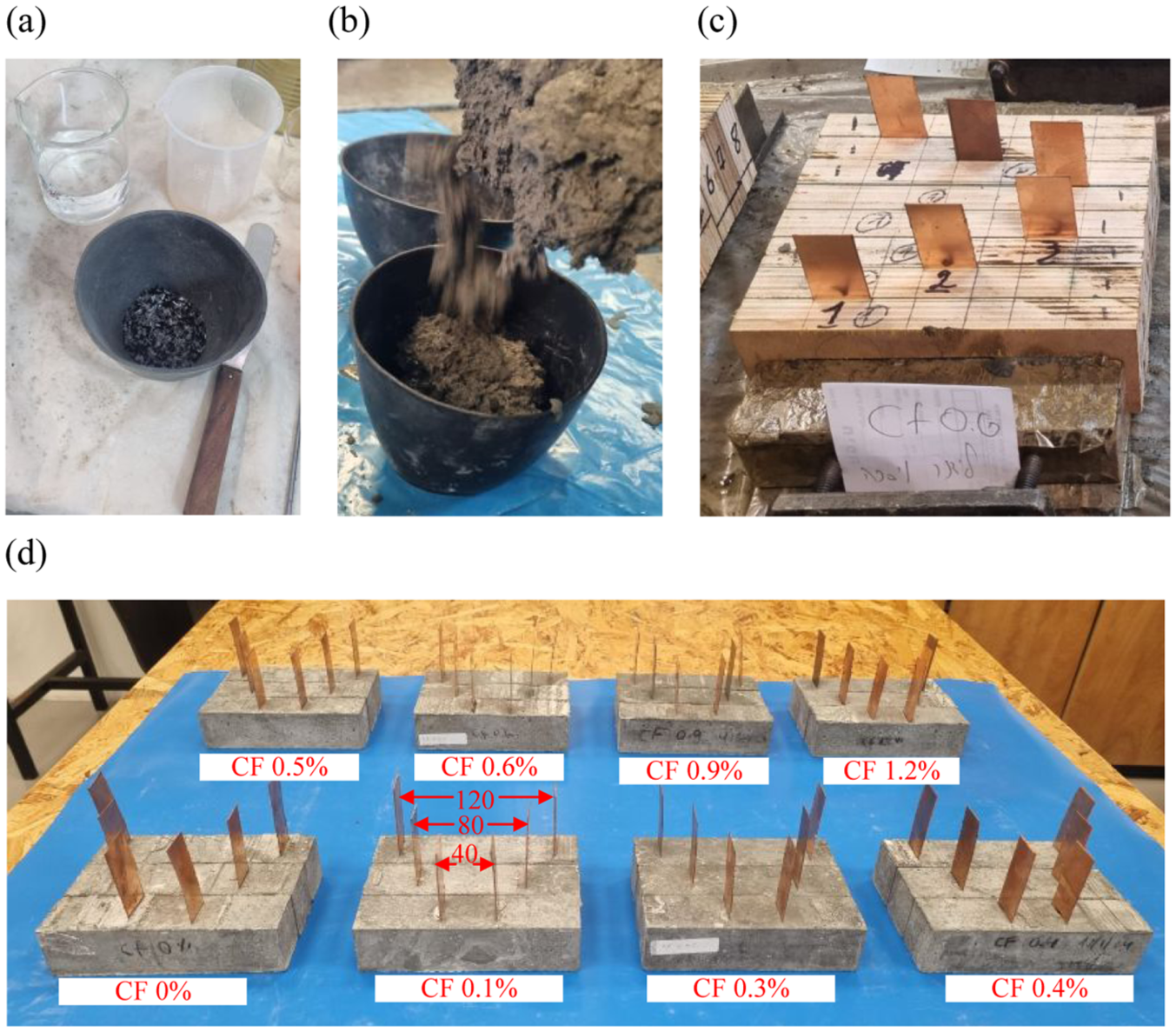
Production of electrically conductive concrete beams: (a) Additive short carbon fibers, (b) Casting of cementitious matrix, (c) Specimens within molds, and (d) Specimens for electrical conductivity investigation.
Mechanical properties
The mechanical tests were performed with Controls loading machine (Model C92Z10, force capacity 500 kN for compression test) in a load control mode with a loading rate of 0.5 MPa/s. The flexural and splitting strength tests are performed with a flexure testing device for mortar prisms (Model 65-L0019/B). The tests were performed at the age of 28 days.
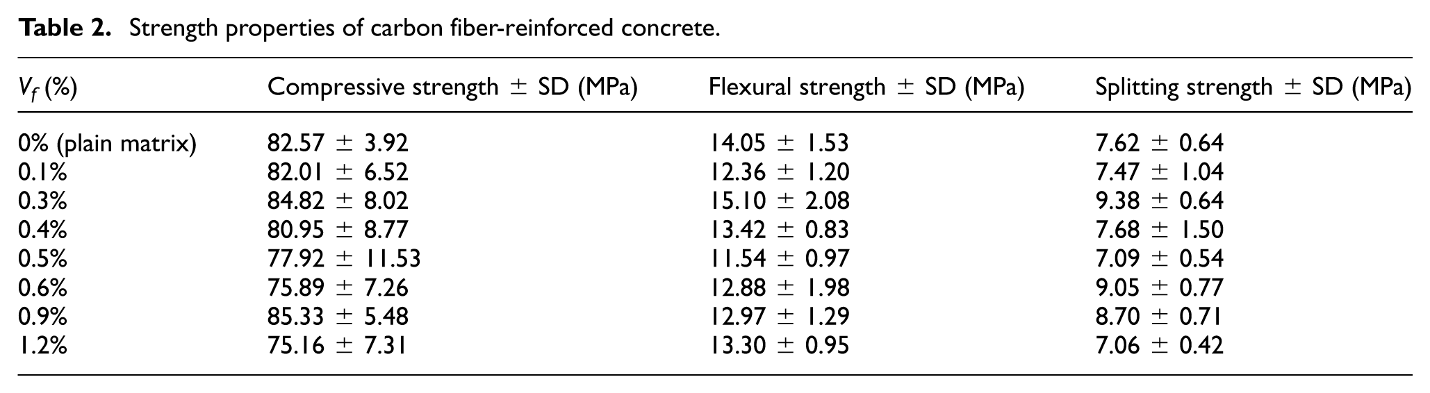
Table 2 summarizes the strength properties of the concrete with respect to the volume fractions of fibers. It is seen that the contribution of additive short fibers to the strength properties is not significant. It is associated with the relatively high strength properties of the plain matrix. In case of lower grades of concrete, the effect of the CFs on the concrete’s strength is more dominant.57–60 Although additive CFs have almost no contribution to the strength properties, they contribute to the ductility and cracking control of TRC elements.59–62 Accordingly, improved mechanical behavior is expected in the case of fiber-reinforced matrix.
Strength properties of carbon fiber-reinforced concrete.
Electrical characterization
The goal of the electrical characterization is to determine the percolation ratio with respect to the investigated compositions. It is performed by connecting the two copper plates, that were embedded within the beams, to the LCR analyzer and measuring the electrical impedance spectrum. The chosen frequency range is specified as f = 370–560 kHz; see also section “Sensory concept.” In this arrangement, the concrete body, which has resistive and dielectric properties, is located between the two conductive parallel copper plates. As a result, an electrical scheme of parallel RC electrical setup is formed; see Equations (1) and (2). The measured impedance spectrums are used to evaluate the values of R and C by using the post-process procedure, as described in section “Sensory concept.” The values of the resistor and capacitor are affected by the material’s properties of the medium between the copper plates and the geometrical properties of the specimen, following the known relations:
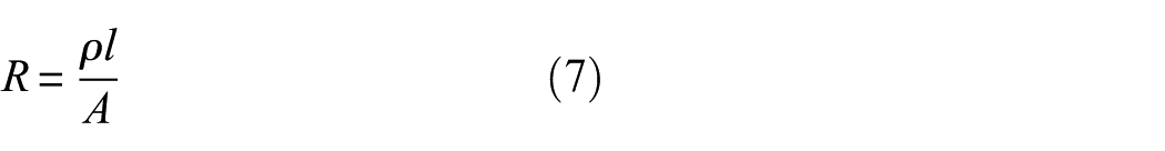
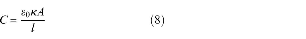
where ρ is the concrete’s resistivity, l is the distance between the copper plates (4, 8, or 12 cm), A is the area of the copper plates (3 × 4 cm2), ε0 is the permittivity of free space (8.854 10−12 F/m), and κ is the relative dielectric constant of the concrete. By using Equations (7) and (8), the values of ρ and κ can be calculated.
The electrical resistivity and permittivity of the concrete matrix, with respect to the fiber contents, are presented in Figure 3. As expected, the electrical properties are affected by the volume fraction of fibers. The electrical resistivity (ρ) of the concrete body decreases significantly due to the increase in fiber’s content; see Figure 3(a). It is seen that this trend is more pronounced up to fiber content of V f = 0.6%. Fiber contents above 0.6% exhibit electrical resistivity that is lower in about an order of magnitude compared to the plain matrix, which indicates that an electrically conductive path is formed within the matrix.
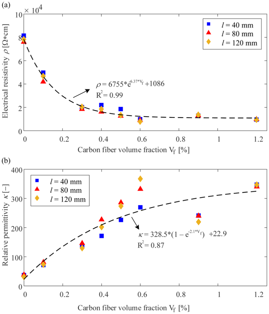
Concrete mixture electrical properties with respect to CF volume fraction: (a) Electrical resistivity and (b) Relative electrical permittivity.
It is seen that the relative electrical permittivity (κ) increases with fibers content; see Figure 3(b). The dielectric behavior of a concrete body is associated with the presence of ionic bonds and moisture,32,33 which affects its capability to separate positive and negative charges (polarization effect).28–33 Additive CFs increase the relative permittivity due to increased conductivity of the medium and concentration of charges in the interface with the matrix, called interfacial polarization.28,30 In our case, the highest relative permittivity is obtained at V f = 1.2%, highlighting the contribution of CFs to the dielectric behavior of the fiber-cement mixture. Therefore, the study uses V f = 1.2% to explore the proposed concept.
Environmental effects
Temperature and humidity variations are known to influence the electrical response of smart cementitious elements, mainly causing offsets or drifts in the measured signals. These effects are mainly pronounced in DC-based electrical measurements.44–46 However, previous studies on smart concrete elements using AC-based measurements 49 have shown that this response is mainly affected by ambient temperature variations. In the present study, all experiments were conducted under laboratory conditions with relatively stable temperature and humidity; therefore, environmental compensation was not required. It is recognized that a comprehensive investigation of environmental effects is essential for field implementation of the smart sensing elements. However, this is beyond the scope of the present study and will be addressed in future work.
Carbon-based textile—hybrid sensory device
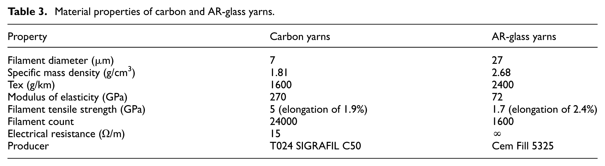
In the hybrid TFRC element, the textile functions as the main reinforcement system and as an internal sensory device. The study uses a biaxial grid mesh composed of carbon yarns in the warp direction and Alkali-Resistant (AR)-glass yarns in the weft direction; see Figure 4. The spacing between the carbon yarns in the warp direction is about 5–6 mm, and that between AR-glass yarns in the weft direction is 7–8 mm. The properties of the yarns are summarized in Table 3.
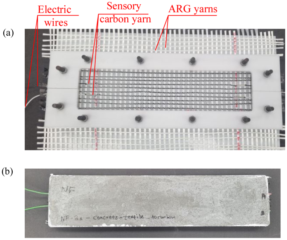
(a) Carbon-based textile within the mold before casting and (b) Smart TRC beam.
Material properties of carbon and AR-glass yarns.
The smart sensory capabilities are explored in cases of plain concrete matrix and with additive CFs. The use of AR-glass yarns in the weft direction aims to prevent direct electrical linkage between parallel carbon yarns enabling to focus on the electrical properties of the concrete body. The electrical connections are performed on one side of the beam to allow measurement of the medium between yarns. It is done by threading wire ferrules through the carbon yarns and crimping them with a crimping tool to electrical wires.
Production of hybrid TRC beams
Two types of matrices are investigated: one is plain concrete and the other is with additive CFs. The dimensions of the beams are width 70 mm, length 300 mm, and height 15 mm. The beams are reinforced with a single layer of textile (see the section “Carbon-based textile—hybrid sensory device”), positioned 5 mm above the lower face of the beam. The location of the textile is specified corresponding to the tensioned zone of the beam; see Figure 5. The textile was slightly pretensioned in all directions within the mold to ensure its position during the casting process; see Figure 4(a). The matrix is cast and cured in lime-saturated water; see further details in the section “Production of PC matrix with additive CFs.”
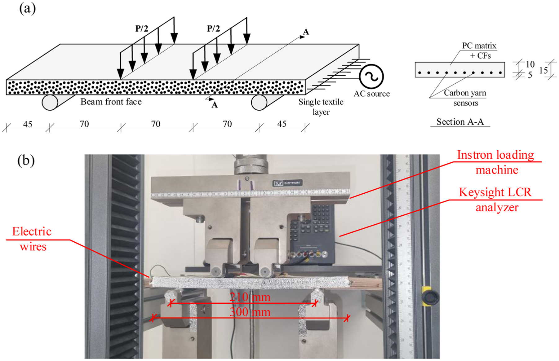
(a) Schematic layout of four-point bending experiment and (b) Mechanical loading and monitoring setups.
Loading profile and monitoring setups
The study investigates textile-reinforced specimens under a four-point bending scheme by using an Instron loading machine (Model 5996 with force capacity of 10 kN). Figure 5 presents the loading scheme, the electrical integration to the DAQ system, and the monitoring setups. The span between supports is 210 mm, and the distance between loads is 70 mm. The following parameters are monitored during the experiments: the electrical impedance spectrum using an LCR analyzer; the load using the loading machine; the mid-displacement of the beam using a linear variable differential transformer (LVDT) sensor (Instron 2601-044); and the strain and displacement profiles using digital image correlation (DIC) technique (camera model: Imager M-lite 9 M with a resolution of 4096 × 2168 pixels), with the analysis performed using the commercial software LaVision DaVis 10
The experimental investigation is performed by two loading scenarios: incremental monotonic step loading and cyclic loading. The loading is performed in a displacement control mode. The displacement rate is determined as 0.1 mm/min. Figure 6 schematically illustrates the two types of loadings on a common mechanical response of the TFRC element.
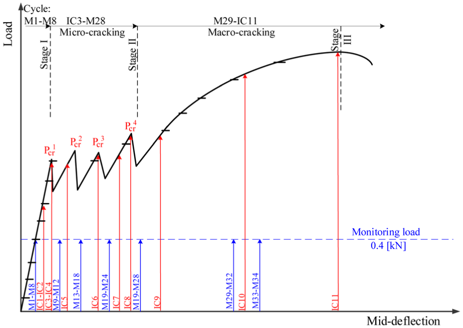
Schematic illustration of incremental monotonic and cyclic loadings with respect to common load-deflection curve of TRC beams.
Incremental monotonic step-loading experiment: The goal of this experiment is to prove the sensory capabilities by gradually increasing the strain level in the beam. The study explores the entire structural response from the healthy stages, before cracking, to the formation of distributed micro-cracks, and up to the occurrence of advanced macro-cracks. Therefore, the specimens are loaded gradually. The load level was increased in constant incremental step-loads of 0.1 kN. The continuous black line in Figure 6 schematically demonstrates the monotonic loading with the target load levels. After reaching each incremental target load level, the load is maintained for 200 s. The chosen time period corresponds to approximately 85 impedance spectrum scans, providing sufficient data at each load level, and allowing to explore load relaxation at the various structural stages. The correlation between the electrical-mechanical responses at incremental target load levels is performed by adopting the concept of the GF.
Cyclic loading experiment: In order to demonstrate the monitoring capabilities of the smart TFRC beams, cyclic loadings are investigated. The study uses two types of load cycles: (a) Monitoring cycles (referred to as M-cycles) that were performed at a load level of 0.4 kN, which is a relatively low level preventing degradation of the structural health; (b) Increased load cycles (IC-cycles) that gradually increase the load levels. The goal is to gradually degrade the structural health of the beams and by that to investigate the structural-electrical correlation and the capability to detect cracking. Therefore, the mechanical and electrical responses are compared after the formations of each crack. The loading pattern of the experiment is designed as two monitoring cycles followed by an increased load cycle and repeats alternately; see Figure 6. If a crack is formed at IC cycle, after the consecutive monitoring cycles, the next IC cycle load level is the same as the previous IC cycle.
Each load cycle, either monitoring or increased cycle, is composed of a non-loaded phase of 100 s, loading to the target load, holding for 100 s and unloading. Holding the load for 100 s aims to provide sufficient data while focusing on the different monitoring levels at the different structural stages. Note that similar to the incremental loading procedure in which the load is maintained for 200 s at each load level, the two consecutive monitoring cycles provide an equivalent amount of measurement at each mechanical stage.
By applying these two types of loading scenarios across different specimens, the study aims to demonstrate the repeatability and consistency of the sensing mechanism and the resulting mechanical-electrical correlations.
Results and discussion
To demonstrate the proposed sensory concept, the experimental investigation is divided into two main parts according to the loading profile. First, a comparison between the monitoring capabilities of TRC beams with and without additive short CFs under incremental step loading is presented. This part aims to demonstrate the enhanced sensory capabilities of hybrid TFRC beam by quantitively correlating between the structural-electrical responses. Then, the monitoring capabilities of a hybrid TFRC beam are investigated under cyclic loadings with gradual and accumulated levels of damage. It aims to prove the consistency and repeatability of the proposed sensory concept.
Structural-electrical correlation by incremental monotonic loading
The mechanical and electrical responses under incremental step loading of the TRC beam are presented in Figure 7, and of the hybrid TFRC beam in Figure 8. The figures present the applied load versus time with the measured integrative strain, changes in electrical resistance and capacitance, and the formation of cracks. For each beam, twenty-four load steps were performed. The next investigations explore the mechanical-electrical correlations.
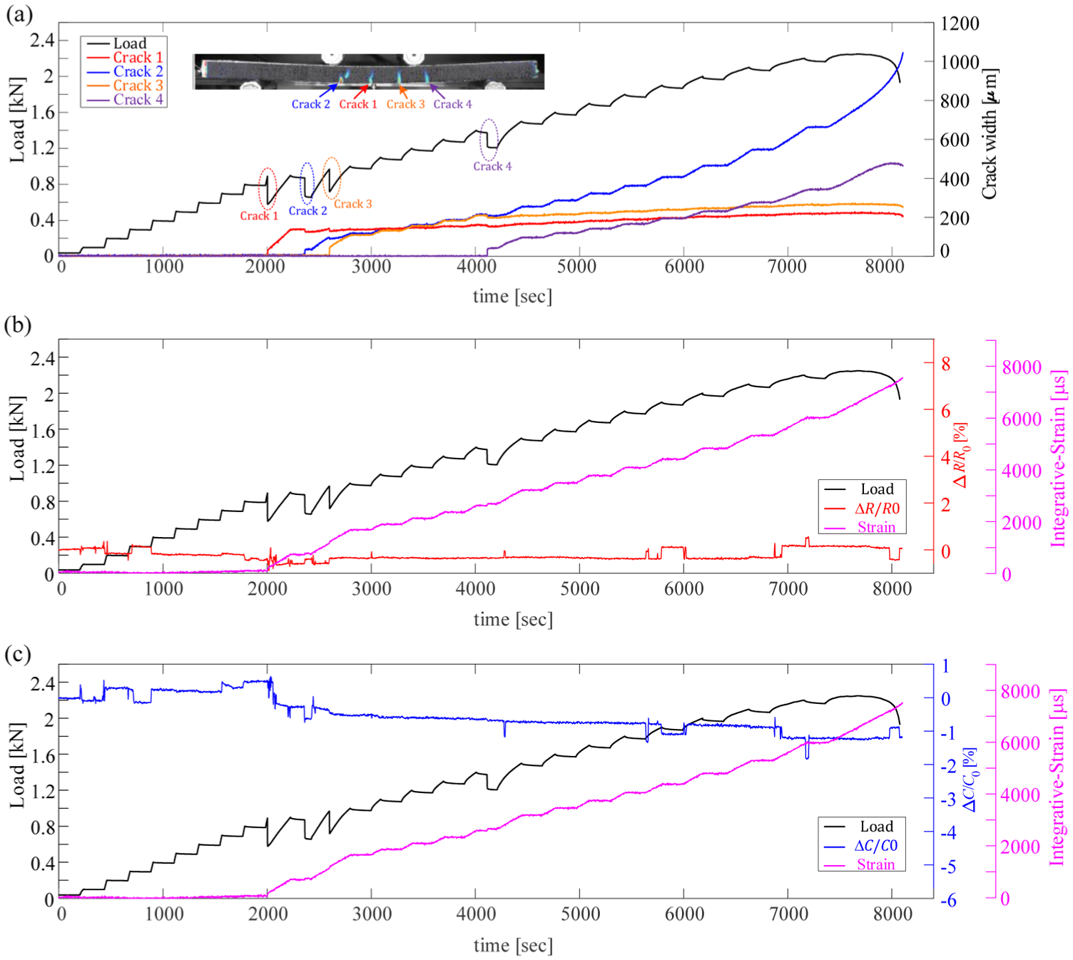
Mechanical and electrical response of TRC beam: (a) Load and crack formations versus time, (b) Load, integrative strain, and relative electrical resistance change versus time, and (c) Load, integrative strain, and relative electrical capacitance change versus time.
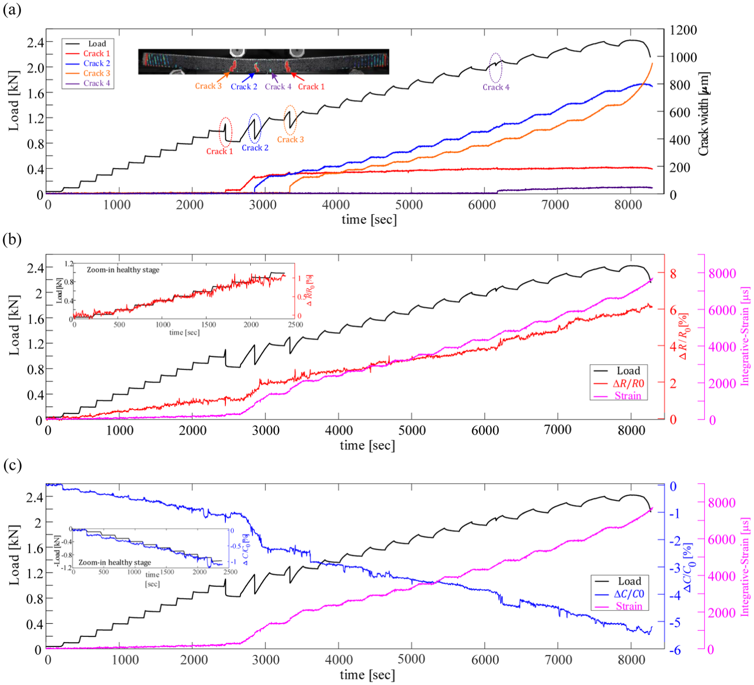
Mechanical and electrical response of hybrid TFRC beam reinforced by short CF: (a) Load and crack formations versus time, (b) Load, integrative strain, and relative electrical resistance change versus time, and (c) Load, integrative strain, and relative electrical capacitance change versus time.
From the mechanical point of view, up to the first cracking load, the beams are in their linear-elastic stage (uncracked) and the measured integrative strains are relatively small. Before reaching the first cracking load, the measured integrative strains are about 150–200 με. In this stage, the equivalent relative stiffness of the beams is governed by the rule of mixture, effected by the matrix, the longitudinal carbon yarns, and the additive short CFs. Therefore, the hybrid beam exhibits slightly higher pre-cracked equivalent stiffness (3.1 kN/mm compared to 2.87 kN/mm). At Stage II, which starts with the formation of the first crack, four cracks are formed in each beam. The cracking loads of the TRC beam are Pcr 1 = 0.89 kN, Pcr 2 = 0.87 kN, Pcr 3 = 0.97 kN, Pcr 4 = 1.37 kN, and that of the hybrid TFRC beam are Pcr 1 = 1.10 kN, Pcr 2 =1.17 kN, Pcr 3 = 1.29 kN, Pcr 4 = 2.06 kN. It is seen that the additive short CFs increase the cracking loads by about 25%. After the formation of the cracks, at Stage III, the contribution of the textile governs the mechanical response leading to similar relative equivalent stiffness values (0.97 and 1.05 kN/mm) and ultimate loads (2.25 and 2.42 kN).
From the sensory point of view, the investigation focuses on the changes in electrical resistance and capacitance of the matrix (calculated by Equation (2)). The initial electrical properties of the beams, measured before the loading process, are as follows: for the TRC beam R0 = 14.863 kΩ, C0 = 0.024 nF; and for TFRC beam R0 = 2.357 kΩ, C0 = 0.208 nF. The low resistance of the TFRC beam is associated with the electrically conductive path formed by the CFs within the matrix. Moreover, this path enhances the relative electrical permittivity of the concrete body, and as a result increases the capacitance. It should be emphasized that these measurements are taken by the carbon yarns and are in good agreement with the results taken from copper plates, as described in the section “Electrical characterization.” These results yield preliminary proof of the capability of the carbon-based textile to serve as smart sensory devices.
The effect of the CF additives on the electrical response is investigated in Figures 7 and 8 for TRC and TRFC specimens, respectively. It is observed that additive CFs lead to significant enhancement in the monitoring capabilities of the beams. In the case of the TRC beam (without additive CFs), changes in relative electrical resistance and capacitance are negligible (Figure 7(b) and (c)). Furthermore, no consistent trends are observed or follow the mechanical loading. Therefore, it can be concluded that in the case of a plain concrete body, changes in electrical properties cannot be used to monitor its structural health by the proposed concept. These results further highlight the need to use an electrically conductive additive for the development of smart concrete elements.1–6 Therefore, the next investigation focuses on the hybrid TFRC beam; see Figure 8.
Figure 8(b) and (c) demonstrates that, in general, the measured electrical resistance increases, while the capacitance decreases with increasing flexural load. It is also seen that these changes consistently follow the mechanical loading pattern. It is associated with the load-carrying mechanism. Up to the first cracking load, the matrix and the short fibers carry most of the tensile stress. Therefore, changes in electrical properties are affected by two mechanisms: slight tensile elongation of the CFs and increase in relative distance between them. These results are consistent with results of compression tests that are reported in the literature, in which electrical resistance decreased under compression stress and increased upon unloading.2,3,19,21
As micro-cracks are formed, the continuity of the conductive medium is disrupted but not disconnected. The short fibers, which are characterized by higher pullout strain than the cracking strain of the concrete, bridge over the crack surface. Since the fiber content (V f ) is above the percolation ratio, the electrical path is still active enabling continuous monitoring capabilities. Here again, both electrical properties follow the magnitude of the applied load and the integrative strain. The electrical resistivity increases while the permittivity decreases due to tensile straining. At the advanced stage, two micro-cracks extended to macro-cracks (above 200 μm). It yields to further straining of the concrete matrix and gradual pullout of CFs between existing cracks leading to further electrical changes.
Quantitative demonstration of the consistent structural-electrical correlation is presented by using the concept of transverse GFs, calculated by Equations (6) and (7). Figure 9 presents changes in the relative electrical resistance and capacitance with respect to the integrative strain along the beam (purple dots). Two GFs are investigated: in Figure 9(a) a transverse GF for the resistance (
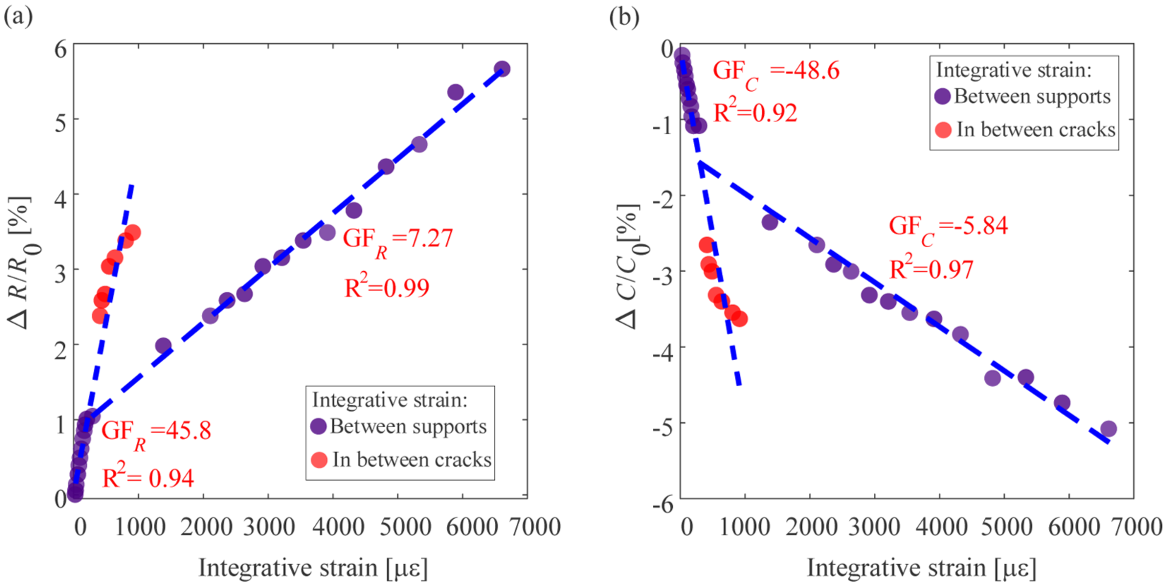
Mechanical-electrical correlation by GFs: (a) Relative resistance change versus integrative strain and (b) Relative capacitance change versus integrative strain.
It is further observed that the values of GFs are higher at the healthy stage compared to the cracked stage. The reason is associated with the different stress-carrying mechanisms at these stages. Up to the cracking strain, the tensile stress is carried by the entire conductive medium (matrix and CFs) resulting in higher strain sensitivity. At the cracked stage, the load-carrying mechanism is governed by the CFs that are pulled out of the matrix and by the carbon yarns that bridge over the crack’s surface. As a result, due to local strain concentration at the cracked zones, the integrative strain increases at a higher rate than the straining of the matrix, yielding a lower GF value. To eliminate the contribution of the carbon yarns to the integrative strain, and to solely focus on the strained conductive medium, Figure 9 also presents additional correlation based on the strain in the matrix. It is calculated in between cracks represented by the red dots in the figure. It is seen that this correlation exhibits higher GF values that are consistent with the healthy stage of the element. This means that a single value of GF, for each electrical property, represents the entire response, proving that the measured electrical signal is associated with the conductive medium. The two representations of the GF values enable crack detection and correlation with strains and the structural stage.
It is further concluded that although strains are measured in the longitudinal direction of the element, and cracking occurs in its perpendicular direction, the carbon yarns are capable of sensing changes in the matrix’s electrical properties.
Structural-electrical correlation by cyclic loading
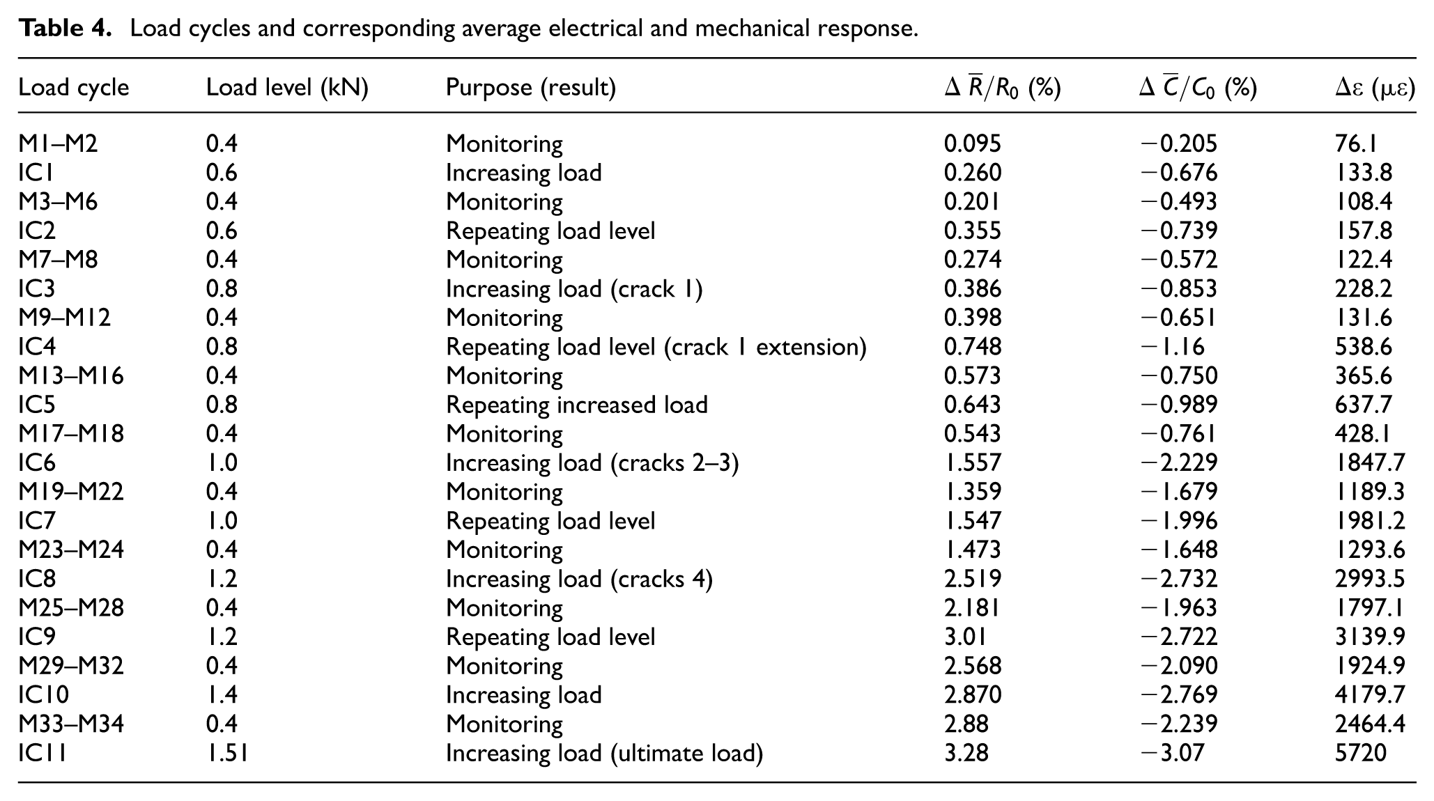
To further prove the smart monitoring capabilities of the proposed concept, the next investigation performed cyclic loading and unloading procedure at the various structural stages, from the healthy stage (uncracked beam) and up to the ultimate load. Figure 10 presents the applied load and the formation and propagation of cracks during the cyclic loadings. The mechanical and electrical responses are presented in Figure 11. The figure presents the load level (black line), the measured integrative strain (pink line), and changes in electrical properties. Figure 11(a) presents the relative electrical resistance change, and Figure 11(b) presents the relative capacitance change. Table 4 summarizes the loading cycles, and their corresponding electrical changes and measured strain. The experiment includes 45 load cycles. It consists of 34 monitoring cycles, referred as M-cycles with a constant load level of 0.4 kN, and 11 gradually increased load cycles, referred to as IC-cycles. The relatively high number of load cycles aims to highlight the consistency and repeatability of the monitoring capabilities of the hybrid TFRC element.
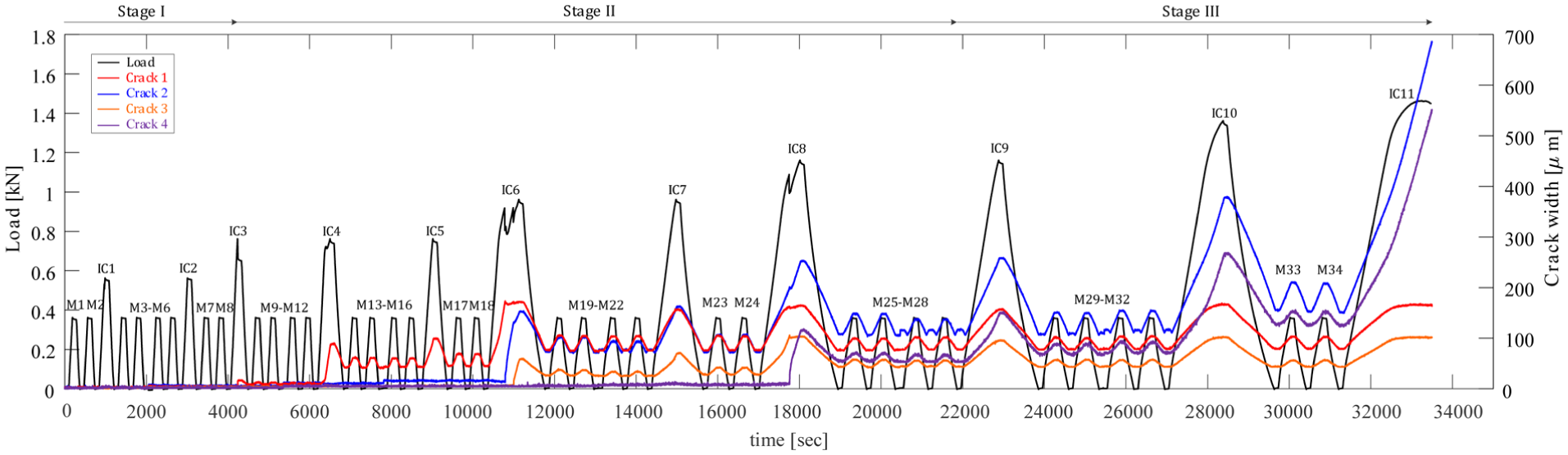
Mechanical response of hybrid TFRC beam under cyclic loadings: Load and crack formation versus time.
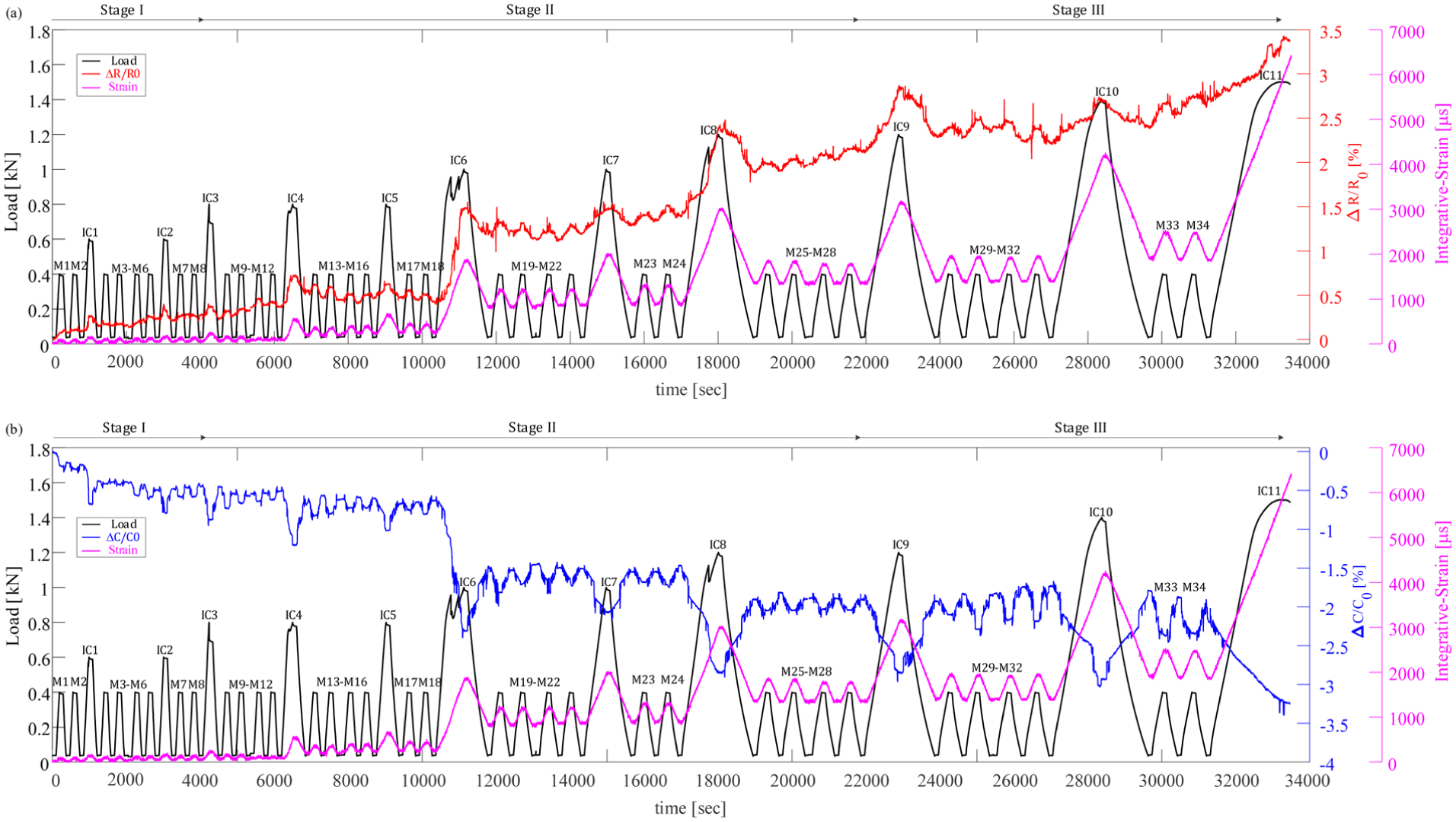
Mechanical and electrical responses of hybrid TFRC beam under cyclic loadings: (a) Load, integrative strain, and relative electrical resistance change versus time and (b) Load, integrative strain, and relative electrical capacitance change versus time.
Load cycles and corresponding average electrical and mechanical response.
Structural response of TFRC beam under cyclic loading
It is seen that up to cycle M8 no cracks are observed, and the beam is in its uncracked stage. A slight drop in the measured load is observed in cycle IC1. This load drop is not associated with cracking. It is verified by repeating the same load level in cycle IC2, in which no load drop or residual strain are observed. The first micro-crack is formed in cycle IC3, at a load level of Pcr 1 = 0.80 kN. The width of the crack in this cycle is 20 μm; see Figure 10. Load cycle IC4 is at the same load level as IC3, leading to an increase in the width of the first crack to approximately 80 μm, and to an irreversible residual integrative strain of 100 με; see Figures 10 and 11. Load cycle IC5 is performed at the same load level as of cycles IC3 and IC4. It aims to explore and verify the monitoring capabilities under this cracking stage; see Figure 6 and Table 4. Additional micro-cracks were observed in cycles IC6 and IC8 with cracking loads of Pcr 2 = 0.95 kN, Pcr 3 = 0.96 kN, and Pcr 4 = 1.13 kN. The formation of distributed multiple micro-cracks indicates that load cycles IC3 to M28 are considered as the design stage of the element. Additional increase in the load level leads to extension of the existing cracks and is accordingly considered as the damage stage (Stage III). The experiment terminated at load cycle IC11 with load of 1.51 kN; see Figure 10 and Table 4. Note that the ultimate load level and the cracking load levels under cyclic loading are significantly lower than under incremental step loading. It is associated with the loading and unloading to relatively high loads, reflecting a fatigue phenomenon that degrades the structural health by breakage of the sleeve filaments within the carbon yarns, widening of cracks, and pullout of CFs.
Monitoring capabilities of the hybrid TRC element
From Figure 11, it is seen that the relative changes in both resistance and capacitance follow the mechanical loading. It is further seen that the electrical response demonstrates good consistency and repeatability of consecutive monitoring cycles in similar structural stages.
In Stage I, the beam is uncracked, and the response is governed by tensile straining of the matrix and short CFs (as illustrated in Figure 1(b)). Straining of the matrix triggers an increase in electrical resistance and a decrease in capacitance. At load cycles M1–IC1, residual electrical and mechanical changes are observed even though no cracking occurs. It is associated with the initial self-organization of the experimental setup in the first several cycles. The next monitoring cycles, M3–M6 and M7–M8, yield consistent and repetitive response.
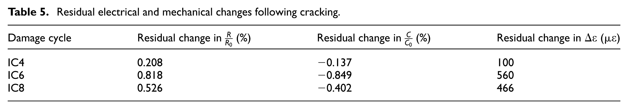
In Stage II, at cycles IC4, IC6, IC8, rapid changes in the matrix’s electrical resistance and capacitance are observed; see Figure 11. It is associated with the formation of micro-cracks that yield local disruptions in the conductive medium that affect the electrical-mechanical mechanism. The short CFs electrically bridge over the cracks and keep functioning as internal sensors that measure changes in the electrical properties of the matrix. The electrical responses are consistent at similar cracking scenarios such as in cycles M13–M18 before and after cycle IC5 (single micro-crack), and in cycles M19–M24 before and after cycle IC7 (distributed micro-cracking); see Figure 11. The ability to distinguish accumulated cracking is observed by the irreversible effect of cracking on the electrical properties of the matrix. Table 5 summarizes the residual changes in electrical resistance, capacitance, and integrative strain following the formation of each crack. It is observed that the irreversible changes are accumulated due to the formation of new cracks, enabling crack detection. Furthermore, the changes in electrical properties in the next cycles, calculated by the relative change in each cycle, increase as the structural health of the element degrades.
Residual electrical and mechanical changes following cracking.
In Stage III no new cracks are formed, and the existing cracks widen and propagate; see Figure 10. At this stage the CFs are gradually pulled out at the crack’s surface and the longitudinal yarns govern the load-carrying mechanism; see further explanation in the section “Structural response of TFRC beam under cyclic loading.” Mechanical and electrical changes are associated with straining of the matrix between the cracks. Therefore, the trend of the relative changes in resistance and capacitance is maintained along this stage.
To explore the consistency of the smart TFRC element, a structural-electrical correlation based on the IC measurements (increasing load levels and strains) is compared to the correlation in the cracked stage of the incremental loading; see Figure 12. Similar to the incremental monotonic loading, the cyclic loading experiment yields a linear correlation. The values of
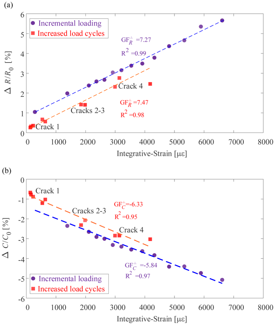
Comparison of the mechanical-electrical correlations of incremental monotonic step loadings and cyclic loadings: (a) Relative resistance change versus integrative strain and (b) Relative capacitance change versus integrative strain.
These results demonstrate the electrical sensitivity of the element and its capability to monitor the response at various loading scenarios. The good consistency and repeatability of the mechanical-electrical correlation across different specimens and loading procedures highlight the potential of the proposed smart TFRC beams as advanced self-sensory elements.
Summary and conclusions
This study presented a new self-sensing approach to monitor the structural health of hybrid TFRC elements by using carbon yarns as internal sensory devices. The proposed new concept is based on measuring the response spectrum of the impedance of two parallel carbon yarns which enabled simultaneous sensing of changes in electrical resistance and capacitance of the conductive medium between the yarns with no need for external sensory devices. These changes were correlated to the mechanical strain and the structural stage of the element.
The study conducted a preliminary investigation into the effect of additive short CFs on the mechanical and electrical properties of concrete with varying fiber contents, focusing on the percolation ratio of the mixture. The study found that while CFs don’t have a significant effect on the strength properties of the high-performance concrete, they have a major effect on the electrical resistivity (ρ) and permittivity (κ). An electrical percolation behavior, in which adjacent fibers touch each other and create an internal network within the concrete body, was found to occur in fiber contents V f > 0.6%. The highest electrical permittivity was obtained in the mixture of V f = 1.2%. It was demonstrated that compared to plain concrete (V f = 0%), the mixture with V f = 1.2% reduced the resistivity by about an order of magnitude and increased the dielectric constant by two orders of magnitude.
To prove the new smart concept, the study performed incremental step loading and cyclic loading. The study explored the sensory capabilities in TRC beams with and without additive short CFs under incremental step loading. It was found that in case of plain concrete matrix the electrical changes are not consistent, and their intensities are relatively negligible. In the case of smart TFRC element, the improved conductivity of the matrix resulted in a clear correlation to the mechanical response. The change in electrical resistance and capacitance exhibited opposite trends. While the resistance increased the capacitance decreased. Based on these changes, the study offered two separate transverse GFs, for the resistance—
The cyclic investigation highlighted the monitoring capabilities of hybrid TFRC elements, from the healthy stage and up to extensive damage. The electrical responses presented consistent changes, with increasing electrical signals due to the accumulation of damage. Rapid changes were observed as a result of cracking, associated with changes in the conductive medium between yarns and the pullout of CFs. The proposed concept can be used to monitor strain in the element and to determine its’ structural stage offering continuous sensory capabilities under progressive damage. Future research can extend this concept to different matrices, fibers, and textile configurations for the development of smart hybrid TRC elements with SHM capabilities.
The proposed new concept lays the foundation for a new generation of smart concrete elements with integrated SHM capabilities. However, to advance this concept toward practical implementation, additional investigations involving large-scale elements and field validation, including environmental effects, are required.
Footnotes
Acknowledgements
The authors are grateful for the support of Teijin company Ltd for providing short carbon fibers. The authors are also grateful for the help of Eng. Barak Ofir.
Funding
The authors disclosed receipt of the following financial support for the research, authorship, and/or publication of this article: This research was supported by the Israel Science Foundation (grant no. 784/24).
Declaration of conflicting interests
The authors declared no potential conflicts of interest with respect to the research, authorship, and/or publication of this article.
Data availability statement
All the data have been presented in the work.