
Abstract
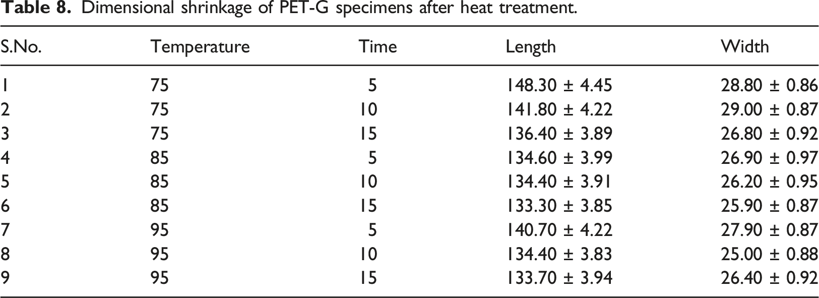
This study investigates the impact of heat treatment on the mechanical, morphological, and dimensional properties of polyethylene terephthalate glycol (PETG), a commonly used thermoplastic in 3D printing. Taguchi L25 orthogonal array (OA) was employed to optimize 3D printing parameters, considering factors such as infill percentage (ranging from 20% to 100%), layer height (0.12 mm to 0.28 mm), layer width (0.32 mm to 0.62 mm), and infill pattern. Following ASTM D638 type IV standards, mechanical testing revealed that the optimal printing conditions included a 100% infill percentage, a layer height of 0.16 mm, a layer width of 0.32 mm, and an infill pattern of 5. Specimen 22, produced under these conditions, exhibited a notable stress-bearing capacity of 46.43 ± 1.394 MPa. These results are consistent with previous studies that underscored the significance of high infill percentages and finer layer dimensions in enhancing tensile properties. Subsequently, these optimized specimens were exposed to various heat treatment conditions. It was discovered that heat treatment at 85°C for 15 min yielded the most significant improvements, increasing the stress-bearing capacity to 53.462 ± 1.604 MPa, representing an impressive ∼16% enhancement compared to non-heat-treated specimens. However, this treatment also led to increased brittleness. Morphological analysis using Scanning Electron Microscopy (SEM) further substantiated the findings. Specimens subjected to heat treatment at 85°C exhibited fewer voids and porosities than those printed with lower infill percentages and larger layer dimensions. These observations underscored the importance of adequate infill density and finer printing details for optimizing strength. Regarding dimensional stability, dimensional changes were meticulously measured after heat treatment. Notably, specimens subjected to heat treatment at or near the glass transition temperature (Tg) of PETG experienced the most significant shrinkage. Specimen 6, treated at 85°C, displayed the highest shrinkage, with length and width reductions of 133.30 ± 3.85 mm and 25.90 ± 0.87 mm, respectively.
Keywords
Introduction
Fused deposition modeling (FDM) printing is a rapidly advancing technology that offers the flexibility to manufacture intricate objects with a wide range of applications.1,2 Polyethylene terephthalate glycol (PETG) is a popular thermoplastic used in 3D printing due to its remarkable strength, durability, and flexibility. Moreover, PETG finds extensive use in food packaging, medical devices, and consumer goods. The mechanical, morphological, and vibrational properties of 3D-printed PETG have garnered substantial interest due to its numerous advantages, including faster production turnaround, cost reduction, and the ability to craft intricate geometries. 3 A critical determinant of 3D printing success lies in the choice of material, which significantly influences the mechanical, morphological, and vibrational characteristics of the printed objects.4,5 PETG, a relatively new thermoplastic material, has gained prominence in the 3D printing industry owing to its exceptional mechanical properties, ease of printing, and robust chemical resistance. PETG is a copolyester derived from polyethylene terephthalate (PET) and glycol and is commonly employed in packaging materials such as bottles. 6 It is characterized by enhanced flexibility and impact resistance compared to pure PET 7 and excellent chemical and UV radiation resistance, making it suitable for outdoor applications. 8 PETG also offers excellent layer adhesion and minimal shrinkage. 9
However, it is essential to acknowledge that the 3D printing process can significantly influence the mechanical, morphological, and vibrational attributes of PETG. Notable research by Mahesh et al. (2021) focused on enhancing the tensile strength and modulus of PETG by incorporating carbon fiber as a reinforcing agent. 10 The composite's microstructure is shown to be influenced by the type and concentration of fillers used. In another study, Vijyasankar et al. (2022) employed various testing techniques, including tensile, flexural, and thermal conductivity tests, to characterize PETG properties. Their findings indicated that mechanical properties improved with a higher loading content of wood flour within the PETG matrix, albeit at the expense of reduced thermal conductivity. 11 Penumakala et al. (2020) reported that FDM-fabricated PETG exhibited mechanical properties comparable to injection-molded PETG, but these properties diminished with increasing fabrication temperature, highlighting the significance of fabrication temperature in determining the characteristics of 3D-printed PETG. 12 Another study by Szust and Adamski demonstrated that the mechanical properties of FDM-printed PETG were influenced by printing orientation, with the highest tensile strength observed in the z-direction. 13 In a related vein, Garcia et al. (2022) delved into PETG-based composite materials, specifically investigating the impact of carbon fiber reinforcement on tensile strength. The study showed that the carbon fiber reinforcement improved the tensile strength of the PETG-based composite material. However, the addition of a large extent of carbon fiber decreased the break elongation and impact strength. 14
The morphological properties of 3D-printed PETG have also been extensively scrutinized. The degree of crystallinity of 3D-printed PETG increased with higher printing temperatures, resulting in heightened stiffness and strength, as evidenced by Bhandari et al. (2019). 15 Tao et al. (2021) investigated the influence of printing speed and layer height on surface roughness, finding that higher speeds and smaller layer heights produced smoother surfaces. 16 Hanon et al. (2021) demonstrated that printing orientation significantly affected the characteristics and microstructure of FDM-fabricated PETG specimens, with horizontal orientation yielding superior tensile and compression strength compared to diagonal printing. 17 The researchers also observed that the microstructure of the PETG varied with printing orientation, with the horizontal specimens showing a more ordered and uniform structure than the diagonal specimens.
The vibrational properties of 3D-printed PETG have also been explored to comprehend the material's response to external stimuli. Kannan et al. (2020) investigated vibration damping for FDM-fabricated PETG, revealing its favorable vibration-damping characteristics, which could be further enhanced by modifying printing parameters. 18 Similarly, Kumar et al. (2022) examined the characteristics of PETG-MCC composites, demonstrating that input process parameters significantly influenced properties. The study highlighted that increasing print density and printing speed improved modulus and strength, and adding MCC to the PETG matrix enhanced the mechanical characteristics of the samples. 19
Several researchers have studied the mechanical properties of 3D-printed PETG, showcasing its impressive tensile strength, elongation at break, and impact resistance compared to commonly used 3D printing materials like acrylonitrile butadiene styrene (ABS) and polylactic acid (PLA). For example, Kasmi et al. (2021) explored the impact of print orientation on PETG properties, with specimens printed at a zero-degree raster angle exhibiting improved strength. 20 Similarly, Kumar et al. (2021) studied the mechanical behavior of PETG under different loading conditions and observed that the material exhibited high mechanical properties and good ductility. 21 The study by Kichloo (2022) highlighted the role of carbon fibers in enhancing the mechanical and surface properties of PETG filaments, improving crystallinity and filament orientation. 22
The morphological properties of PETG have also been extensively studied. Surface roughness and dimensional accuracy are important factors that limit the application of the FDM-fabricated functional samples. Srinivasan et al. (2020) demonstrated that thinner layers yielded smoother surfaces and greater dimensional accuracy. 23 Zhou et al. (2022) compared PETG, ABS, and PLA at different speeds and infill densities, concluding that PETG exhibited the lowest surface roughness and highest dimensional accuracy. 24 Vinyas et al. (2019) revealed that the PETG/PLA blend filaments exhibited improved mechanical properties and thermal stability compared to pure PLA, with printing temperature and nozzle diameter significantly influencing printing quality and dimensional accuracy. 25 Vidakis (2021) conducted various tests on PETG composites, showing that the reinforcement of TiO2 filler particles significantly impacted tensile strength and thermal characteristics, with 4 wt% being the optimal filler content for enhancing mechanical and thermal properties. 26
A similar study by Gunasekaran et al. (2021) investigated the impact of input process parameters in FDM on PETG composites. The study discerned a substantial influence of the printing parameters on the properties of the composite materials. 27 In a separate investigation, Bhandari et al. (2019) demonstrated that subjecting PETG to heat treatment at 100°C for 4 h yielded notable improvements in its properties. Specifically, the mechanical strength witnessed a 16% increase, while the modulus of elasticity enhanced up to 26% compared to untreated specimens. It is noteworthy, however, that the elongation at break experienced a slight reduction following the heat treatment. 15 Kovacova et al. (2020) observed the effects of hybrid fillers on 3D-printed PETG composites. The study revealed that incorporating hybrid fillers, including graphene oxide, carbon black, and silica, into the PETG matrix substantially impacted the composites' mechanical and morphological properties. Additionally, introducing these fillers enhanced the composite's thermal conductivity and heat deflection temperature, further underscoring the potential applications of these hybrid filler-reinforced PETG composites across various industries, including electronics, automotive, and aerospace. 28 Teraiya et al. (2020) provided insights into the influence of processing parameters on the mechanical properties of PETG materials. Their findings indicated that the nozzle and base temperatures were pivotal in enhancing mechanical properties. The study noted that fabrication speed did not significantly influence these mechanical properties. Furthermore, the processing parameters were found to impact the rheological behavior of PETG material, with elevated temperatures leading to a reduction in viscosity. 29
The vibrational properties of PETG have also been subject to investigation in several studies. Vibrational characteristics, such as natural frequency and damping, are pivotal in designing structures subjected to dynamic loads. For instance, Mahesh (2021) delved into the natural frequency and damping characteristics of PETG components fabricated using FDM and assessed them using a cantilever beam setup. The study identified that the boundary conditions employed for testing and the level of reinforcement within the PETG polymer were decisive factors influencing the damping properties of PETG composites. 30 In addition to the properties mentioned above, it is essential to acknowledge that the composition of PETG and the post-processing treatments applied to it can also significantly impact its overall properties. Pazhamannil et al. (2022) compared the mechanical properties and impact resistance of PETG and PLA printed by an open-source FDM printer, highlighting the superiority of PETG in terms of mechanical properties and impact resistance, particularly after post-processing treatment. 31
In conclusion, PETG exhibits promising attributes for 3D printing, encompassing excellent mechanical, morphological, and vibrational properties. The current state of research on PETG properties and influencing factors provides valuable insights into its potential applications across diverse industries, such as aerospace, automotive, and medical. Further research on PETG is imperative to optimize its properties for specific applications and to explore its potential in new areas, including post-processing techniques for FDM-printed parts. For the present work, the authors aimed to bridge a gap in existing research by conducting a comparative analysis between heat-treated and non-heat-treated PETG specimens, focusing on mechanical, morphological, and dimensional characteristics. This research holds promise for enhancing PETG's properties and expanding its packaging and electronic insulation applications.
Materials & methodology
Material
PETG was selected as the workpiece material for this study due to its widespread use in the polymer industry. The polymer feedstock filament was procured from Numakers Asia LLP in Gujarat, India. The PETG filament obtained from this supplier is biocompatible and has a nominal diameter of Ø1.75 ± 0.05 mm. The purchased PETG material held density 1.27 g/cm3; MFI of 8 gm/10 min and viscosity of 70.0 - 86.0 cm³/g. Figure 1 illustrates the PETG feedstock filament acquired for this research. PETG feedstock filament used in the study.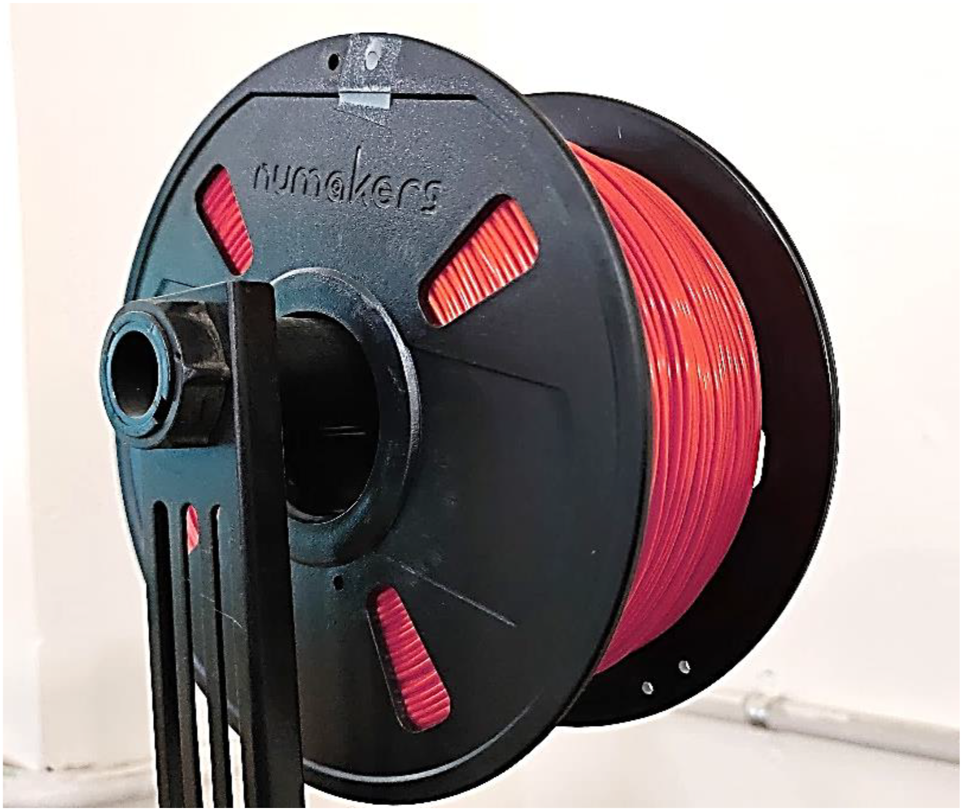
Methodology
Stage 1: Non-heat-treated polyethylene terephthalate glycol specimens
The purchased PETG feedstock filament was utilized in the FDM printing process under specific conditions, as detailed in Table 1. To explore the impact of FDM process parameters on the PETG material matrix, the Taguchi L25 orthogonal array (OA) was employed for selecting the combinations for four input process parameters mentioned below to perform the experiments: • Infill Percentage (5 levels, ranging from 20% to 100%) • Layer Height (5 levels, ranging from 0.12 mm to 0.28 mm) • Layer Width (5 levels, ranging from 0.32 mm to 0.62 mm) • Infill Pattern (5 levels, specific to the FDM machine) FDM printing conditions for stage 1.

For FDM printing, an open-source FDM printer was employed (Model: Divide by Zero, Make: Shenzhen Creality 3D Technology Co., Ltd, Shenzhen, China). Tensile specimens were fabricated following ASTM D638 type IV standards. Figure 2 displays these tensile specimens Tensile specimens produced using an in-House FDM setup (ASTM D638 type IV). Note: The 3D-printed specimens were printed with following fixed conditions. Print speed: 80 mm/s, raster angle: 45°, Build plate temp: 75°C.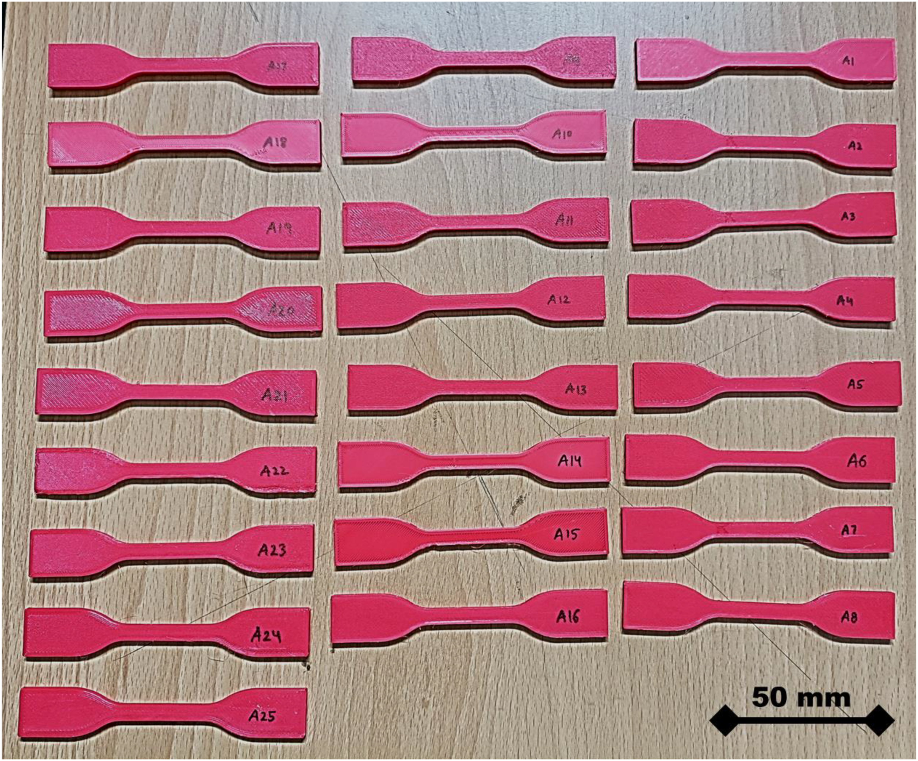
Table 1 lists the 25 specimen details used to prepare the specimens. Taguchi L25 OA was used to prepare the specimens. MiniTab software program with four input parameters of 3D printing equipment was used for Taguchi L25 OA selection and preparation. Five different levels were chosen for each parameter. The Taguchi L25 OA array was utilized to organize the level and parameters for further optimization of processing conditions with a minimum number of experiments, saving cost and time while keeping the same level of integrity for testing.
Stage 2: Heat treatment analysis for optimized fused deposition modeling condition
Following the optimization in the first stage, specimens were reprinted using FDM and subsequently subjected to heat treatment for a comparative analysis of mechanical and morphological properties.
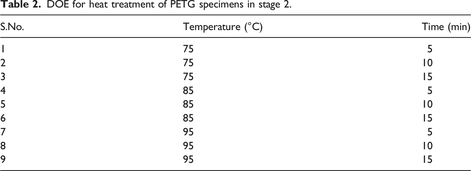
DOE for heat treatment of PETG specimens in stage 2.
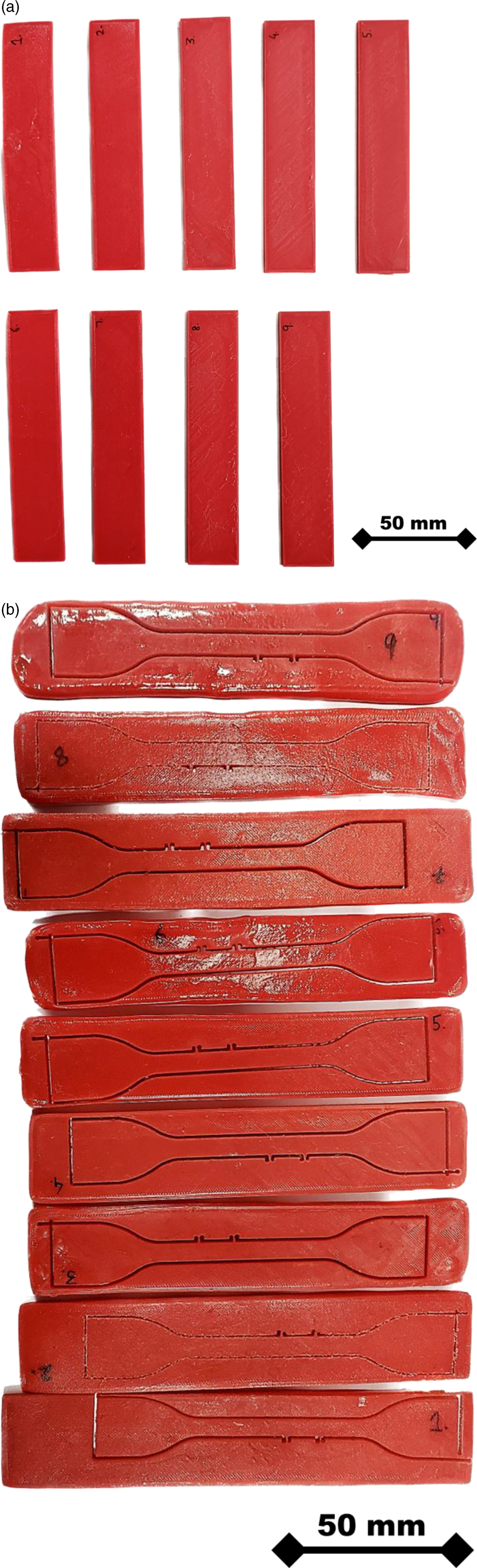
(a) Rectangular 3D-printed specimens with optimized setting of stage 1 and (b) water jet cut specimens after heat treatment. Note: The rectangular sheet was 3D-printed with the optimized setting of stage 1 and after heat treatment the specimens were water jet cut. Thus, the sample which were water jet cut had same 3D-printed aspects as it were in stage 1 that was important for comparison. The information has been added in original manuscript and highlighted with red colored text. As the specimens were first 3D-printed with the 150*100 mm size with the same optimized setting of stage 1 and then further water jet cutting was performed. This method of preparing the specimens does not change the original aspects of 3D printing. The full rectangular specimens printed with optimized setting of stage 1 were heat treated with the given methodology.
Result and discussions
Mechanical results of non-heat-treated polyethylene terephthalate glycol specimens
Mechanical properties of non-heat-treated PETG specimens.
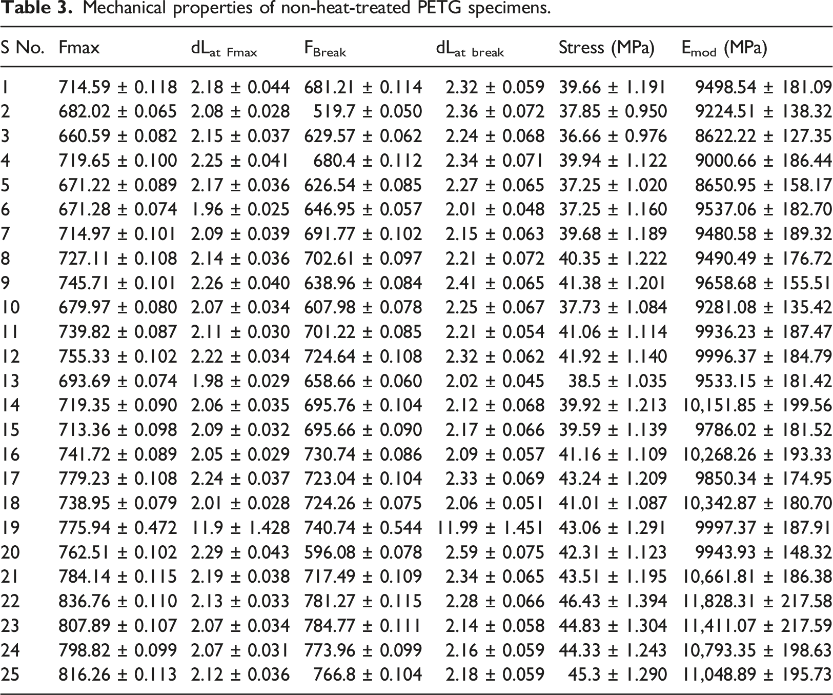
Specimen 22 featured a maximum infill percentage of 100%, a moderate layer height of 0.16 mm, and a minimal layer width of 0.32 mm. Previous research indicates that higher infill percentages lead to better tensile properties,
32
while lower layer height and width improve mechanical results.33,34 Figure 4 illustrates the stress versus strain graph for specimens 3 and 22, highlighting the significant difference in their mechanical performance. This difference resulted in a 9.77 MPa variation in tensile strength between the best and worst specimens. Stress versus strain analysis for specimens 3 and 22.
Specimen 3 exhibited the lowest mechanical performance, likely due to its processing conditions, featuring the lowest infill percentage, moderate layer height, and width. Additionally, the choice of infill pattern 3 had a less pronounced impact on tensile properties than infill pattern 5, which may have contributed to the poor performance of specimen 3. To comprehensively understand the combined impact of all selected input parameters of the 3D printing machine, a Taguchi-based L25 OA optimization tool was employed.
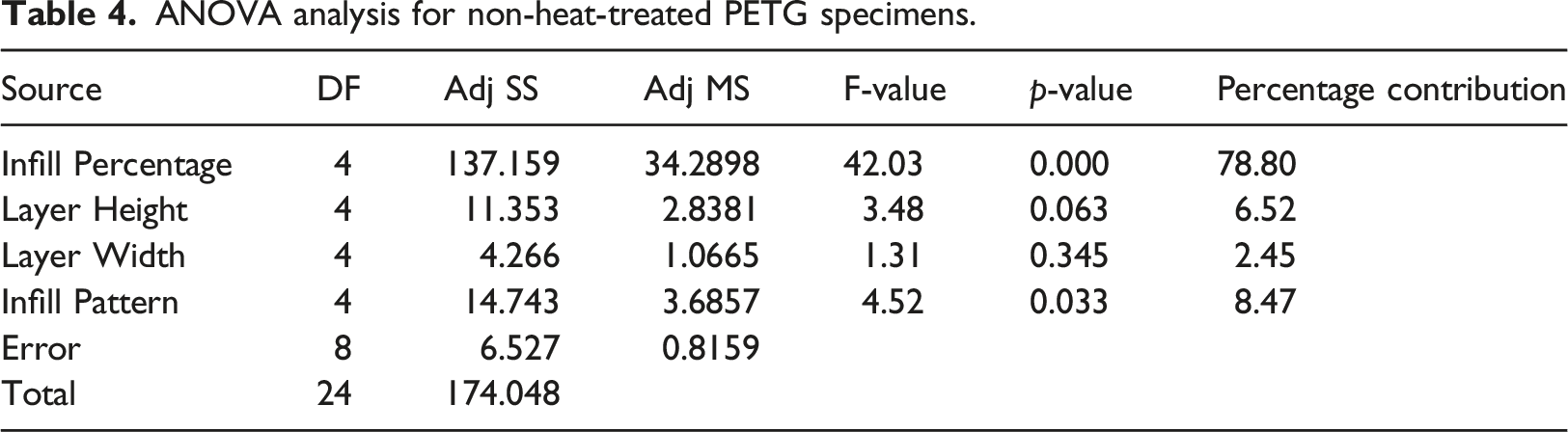
Analysis of variance analysis of non-heat-treated specimens of polyethylene terephthalate glycol
ANOVA analysis for non-heat-treated PETG specimens.

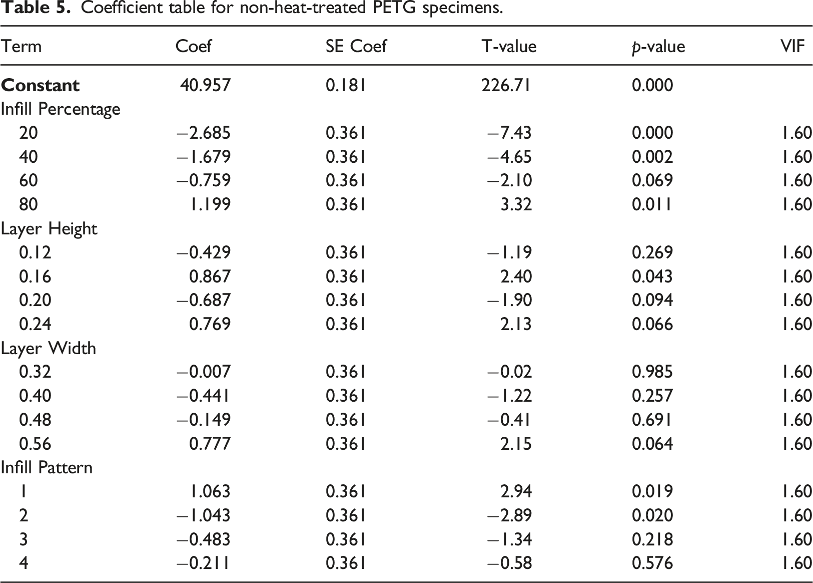
Coefficient table for non-heat-treated PETG specimens.
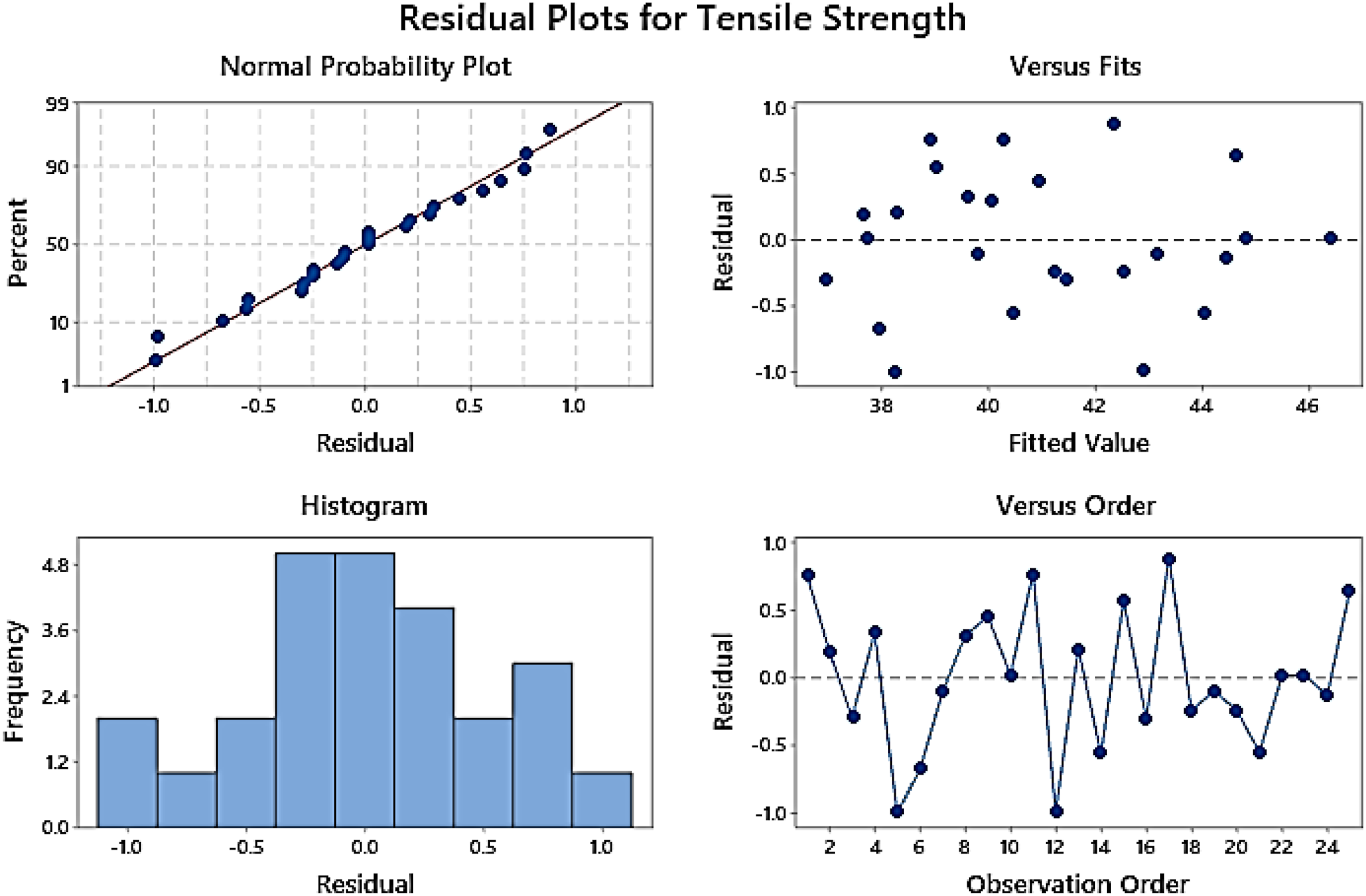
Four-in-one plot for non-heat-treated PETG specimens obtained from fitting a linear model using ANOVA one-way analysis.
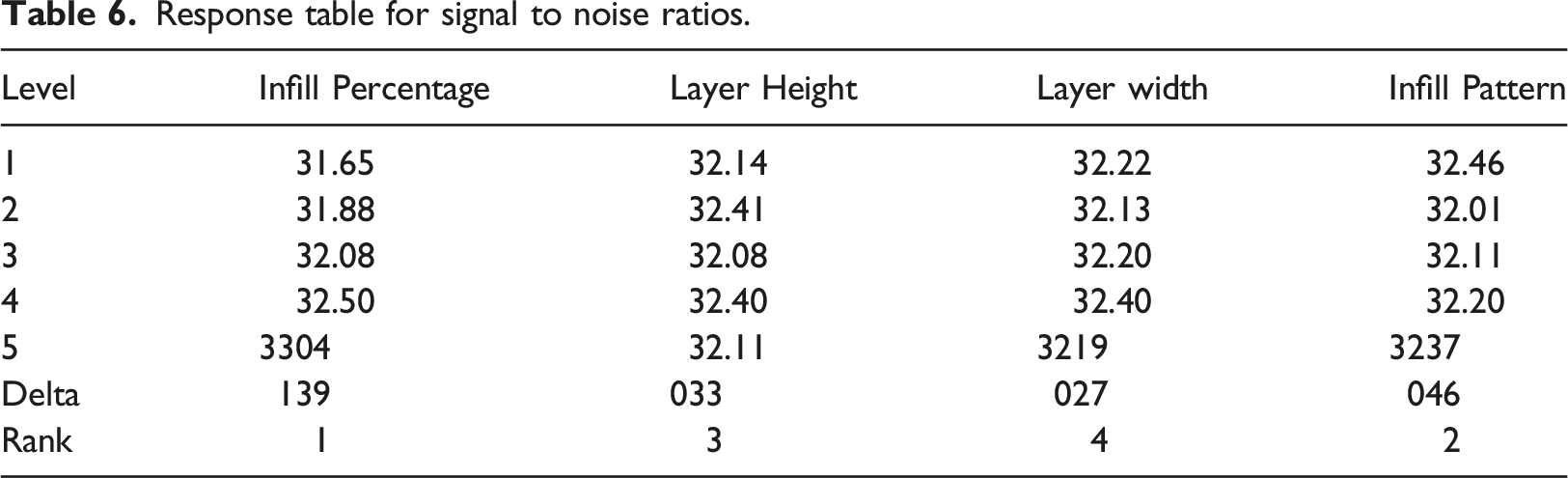
Response table for signal to noise ratios.
Morphological results for normal specimens of polyethylene terephthalate glycol specimens
Examining PETG tensile specimens from stage 1 yielded two distinct cases for further scrutiny – the best-performing specimen (specimen 22) and the weakest specimen (specimen 3). These specimens were subjected to Scanning Electron Microscope (SEM) analysis at varying magnifications. SEM analysis unveiled that Specimen 3 exhibited significant voids, attributed to its 20% infill percentage. The 3D-printed specimen displayed noticeable gaps and voids within its structure. Notably, specimen 3 possessed larger layer height and layer width values than specimen 22. Figure 6 displays SEM images of both specimen 3 and specimen 22. SEM analysis of specimen 22 indicated fewer voids and porosities than specimen 3. This contrast can be attributed to specimen 22’s 100% infill density, lower layer width, and height settings. These observations suggest that low infill density and larger layer dimensions adversely affect the specimen's mechanical strength, while higher infill density bolsters its resistance to external forces. SEM analysis of specimen 3 and specimen 22 at different magnifications.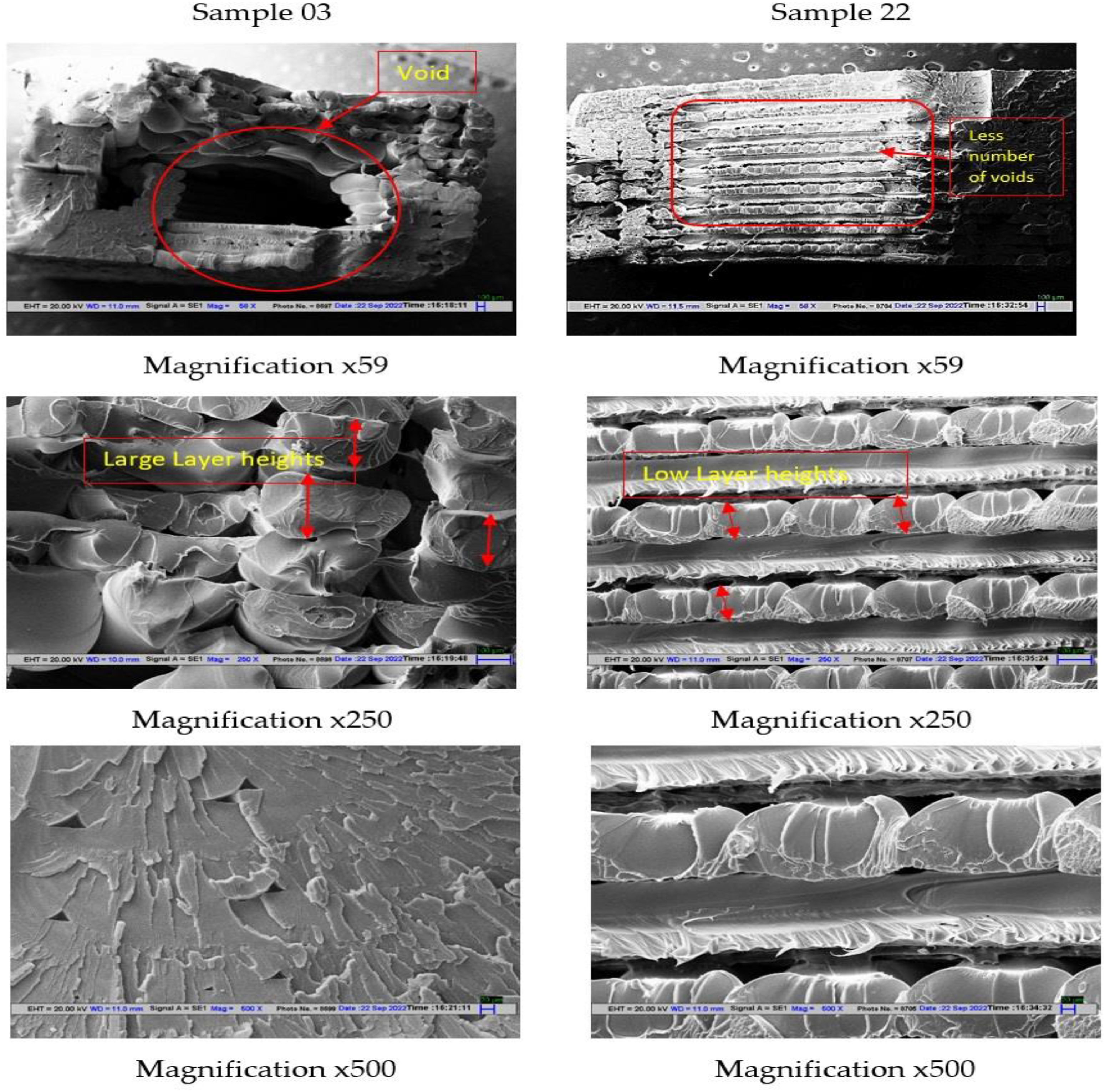
Discussion for post-heat treatment process for optimized fused deposition modeling condition
Mechanical results for heat-treated specimens
Mechanical properties for the heat-treated specimens of stage 2.
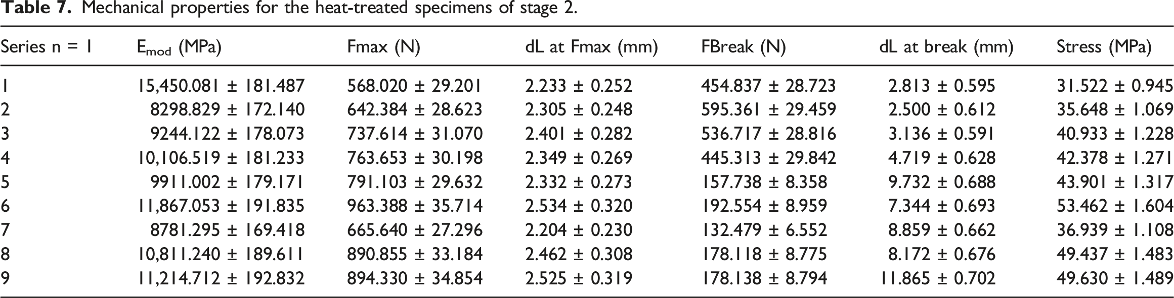
Notably, three specific heat treatment conditions (6, 8, and 9) yielded superior results to their non-heat-treated counterparts. This indicates that heat treatment at 85°C for 15 min positively influences the mechanical properties of FDM-printed PETG components, resulting in a 16% enhancement in stress-bearing capacity. Additionally, it was observed that heat treatment at the glass transition temperature (Tg) produced the most favorable results for PETG, while heat treatment below Tg led to decreased mechanical strength. Heat treatment above Tg exhibited a marginal effect, with Conditions 8 and 9 demonstrating only a 6-7% increase in strength.
The analysis of modulus for heat-treated specimens revealed notable improvements. For instance, specimen 1 of DOE 2 exhibited an modulus of 15,450.081 ± 181.487 MPa, a 30% improvement compared to specimen 22 from stage 1, which had an modulus of 11,828.31 ± 217.58 MPa. Heat treatment at 75°C rendered specimens brittle, resulting in high modulus values and reduced stress-bearing capacity. In summary, heat treatment demonstrated varying effects on modulus and stress-bearing capacity, suggesting that condition 1 may be preferred for maximizing modulus, while condition 6 is advisable when tensile strength is a primary concern. Figure 7 illustrates the percentage change in modulus values for heat-treated specimens compared to the optimized non-heat-treated specimen (specimen 22). Percentage change in modulus values for heat-treated specimens compared to the optimized non-heat-treated specimen.
Morphological analysis for heat-treated specimens
Following the completion of UTM analysis, the destructed specimens were subjected to SEM analysis to elucidate the nature of failure. Figure 8 shows SEM micrographs at different magnification levels. Specimen 1 from the heat-treated specimens exhibited brittle failure, given its modulus value of 15,450.081 ± 181.487 MPa. SEM micrographic analysis revealed a 90° fracture angle without fiber stretching (refer to SEM image of specimen 1 at ×61 and ×100 magnifications). Conversely, SEM images of specimen 6 indicated ductile failure, with visible fiber stretching and neck formation during UTM stretching (see Figure 8, specimen 6 at ×61 and ×100 magnifications). A comparison between SEM images of specimen 22 from stage 1 and specimen 6 from stage 2 highlights the latter's greater ductile failure, corroborated by a break elongation (dL at break) value of 7.344 ± 0.693 mm, in contrast to 2.28 SEM images of specimen 1 and specimen 6 at different magnifications.
Dimensional analysis for heat-treated specimens
Dimensional shrinkage of PET-G specimens after heat treatment.

Rectangular heat-treated PETG specimens.
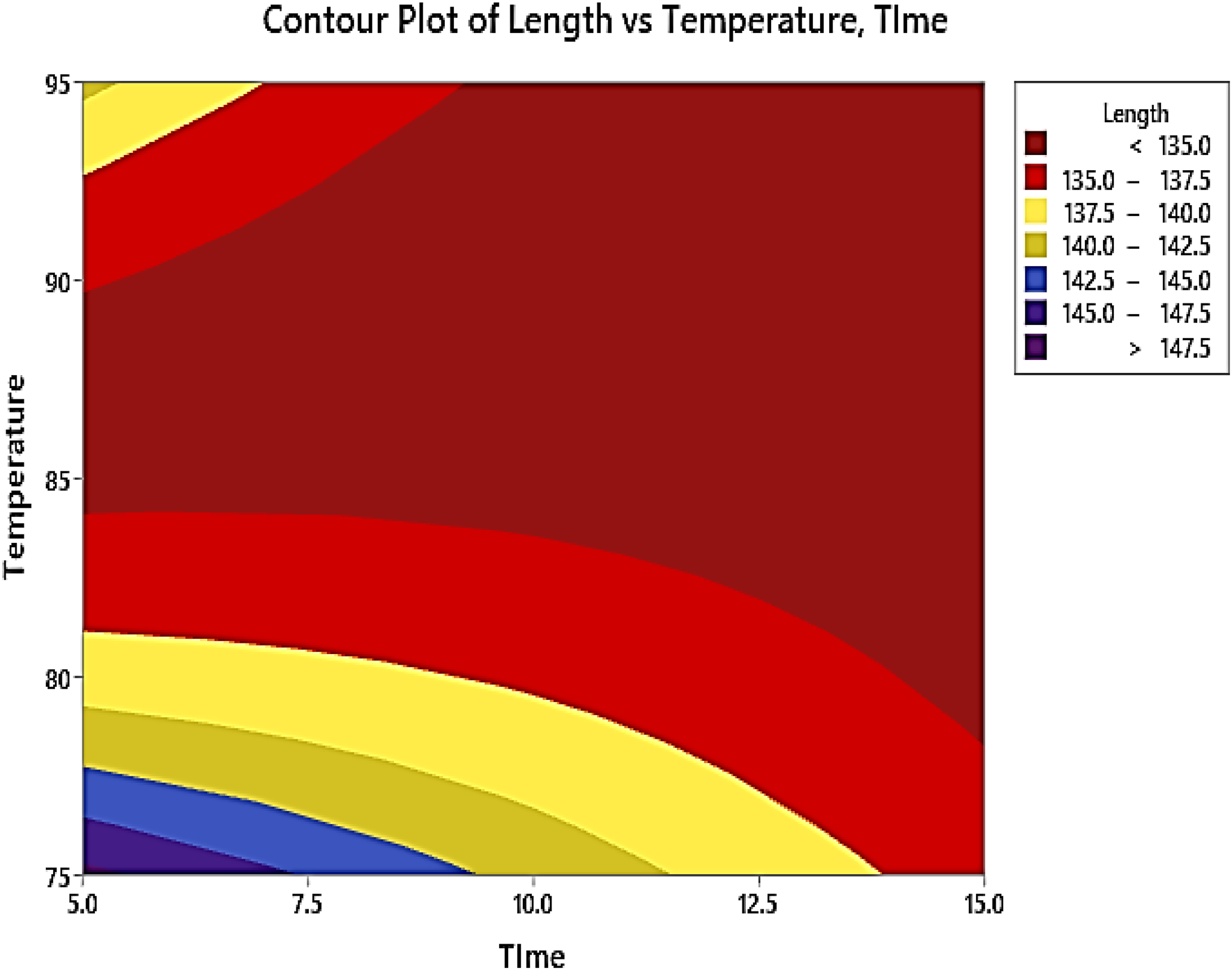
Contour plot of dimensional shrinkage for heat-treated rectangular specimens.
Conclusion
In this study, a comprehensive investigation was conducted into the mechanical and dimensional properties of PETG specimens, focusing on the comparison between untreated specimens and those subjected to post-processing (heat treatment). The key findings and conclusions from the research are as follows: The analysis of mechanical properties led to the identification of specific optimized conditions for FDM printing, including an infill percentage of 100%, a moderate layer height of 0.16 mm, and a minimum layer width of 0.32 mm. These parameters resulted in specimen 22, which exhibited a stress-bearing capacity of 46.43 ± 1.394 MPa. Subsequent heat treatment of the optimized specimens revealed a significant improvement in stress-bearing capacity, with the heat-treated specimen reaching 53.462 ± 1.604 MPa. This represented a ∼16% enhancement compared to the mechanical properties of untreated PETG specimens.
Furthermore, the heat treatment process increased the modulus value, accompanied by increased brittleness. The most effective heat treatment conditions were determined to be at 85°C for 15 min, which positively enhanced the mechanical properties of FDM-printed components. Analysis of SEM images for specimen 6 demonstrated ductile failure, characterized by fiber stretching and evident neck formation during the UTM stretching process. A comparison between SEM images of specimen 22 from stage 1 and specimen 6 from stage 2 indicated that specimen 6 from stage 2 exhibited a more pronounced ductile failure. This was supported by the break elongation (dL at break) values, which measured 2.28 ± 0.066 mm for specimen 22 of stage 1 and 7.344 ± 0.693 mm for specimen 6 of stage 2.
Regarding future scope, further exploration of heat treatment processes in conjunction with other surface treatment methods is recommended to gain insights into the broader mechanical, morphological, and thermal properties of PETG. Additionally, the study was limited to heat treatment under natural room temperature conditions. Future investigations should encompass variations in cooling rates using different media, such as forced circulation and the salt bath method, to achieve the desired mechanical properties for FDM-printed PETG specimens. In summary, this study contributes valuable insights into optimizing FDM printing parameters and the benefits of post-processing heat treatment for enhancing the mechanical properties of PETG. These findings have implications for the broader field of additive manufacturing and the potential for improved material performance in various applications.
Footnotes
Acknowledgements
The authors would like to express their gratitude to “D Y Patil International University, Pune, Maharashtra, India, and CT University, Ludhiana, Punjab, India,” for their invaluable technical support during the material preparation and testing program.
Author’s contribution
Data curation, Sudhir Kumar, S.S.R koloor and Inderjeet Singh.; Formal analysis, Sudhir Kumar, Dinesh Kumar, and Inderjeet Singh; Project administration, Sudhir Kumar, Dinesh Kumar, Inderjeet Singh, and Jonty Mago; Writing—original draft, Sudhir Kumar, and Inderjeet Singh; Writing—review & editing, Sudhir Kumar, Dinesh Kumar, Inderjeet Singh, S.S.R Koloor and Jonty Mago. All authors have read and agreed to the published version of the manuscript.
Declaration of conflicting interests
The author(s) declared no potential conflicts of interest with respect to the research, authorship, and/or publication of this article.
Funding
The author(s) received no financial support for the research, authorship, and/or publication of this article.
Data Availability Statement
No data has been acquired from a third party. The reported data has been generated on CT University premises and originally lies with the corresponding author (S Kumar).