
Abstract
This article presents an ongoing research, aiming to introduce a fabrication procedure for the development of tensile mesh systems. The purpose of current methodology is to establish an integrated approach that combines digital form-finding and robotic manufacturing processes by extracting data and information derived through elastic material behavior for physical implementation. This aspires to extend the capacity of robotically driven mechanisms to the fabrication of complex tensile structures and, at the same time, to reduce the defects that might occur due to the deformation of the elastic material. In this article, emphasis is given to the development of a custom-made end-effector tool, which is responsible to add elastic threads and create connections in the form of nodes. Based on additive fabrication logic, this process suggests the development of physical prototypes through a design optimization and tool-path verification.
Keywords
Introduction
While the fabrication of non-standard and complex shapes is traditionally achieved using single-purpose computer numerical control (CNC) mechanisms and processes, 1 currently the continued development of innovative tools allows the introduction of lightweight materials in the construction of complex shapes, aiming at high precision and elimination of deviations due to their structural deformation during the construction phase. Furthermore, the tendency toward the digital development of grid-like structures based on advanced computational mechanisms and procedures, the ability to optimize the static performance of such systems using genetic algorithms, and the possibility for physical construction through the use of industrial robots allow innovative elastic materials to be introduced and employed.
Such materials like films and threads are considered extremely light and can receive large external loads upon appropriate geometrical configuration and pretension. 2 Pioneer work by Frei Otto in the Stuttgart Institute of Lightweight Structures with soap films involves a balanced distribution of forces on surfaces with minimum area. In this case, the form-finding results depend on fixed parameters such as distance and shape of edges. 3 The form-finding of grid shell structures traditionally is based on a trial-and-error process, on empirical knowledge, and on design parameters derived through physical prototypes. Nevertheless, any attempt to optimize such systems requires an in-depth geometrical analysis, a procedure that in most of the cases is time-consuming, containing geometrical inaccuracies. In addition, the knowledge and skills of designers who are responsible to predict material behavior and possible deformations are often limited.
The application of digital tools for form-finding and material behavior simulation 4 allows the gradual verification of the manufacturing processes. An important factor in this procedure is the static behavior of the system, which varies according to the changes occurring during fabrication. By integrating genetic algorithms into a form-finding process, a large number of design possibilities are obtained, where morphological, structural, and construction criteria can influence the selection of the final forms. In Ahlquist et al., 5 discussion in relation to the implementation of form-finding and optimization processes can be found and particularly the use of form-finding techniques through particle-spring simulation. The use of graphic environment for spring simulation is combined with the results of finite element analysis (FEA) using multi-objective optimization strategies for the creation of digital meshes of elastic threads. Then, numerical results derived through form-finding process are used for cutting and assembling of physical prototypes.
In addition, the application of advanced materials during the construction of complex forms is possible, thanks to the computational investigation of morphologies and the parallel simulation of the construction process, as well as the use of external data acquisition devises, that is, vision systems and control devices, that is, Arduino microcontrollers. 6 This new logic requires the combination of different computational design and advanced manufacturing methods. In this direction, the current development of robotically driven fabrication procedures, which are able to handle complex morphologies and materials, is strengthened by the use of more sophisticated applications than simple industrial end-effector tools, such as hot wire and gripper. 6
Related works in this direction can be found, for instance, in the experimental investigation undertaken in Seyedahmadian et al., 7 where a custom-made end-effector tool is developed for the manufacturing of a shell structure. The tool is used to adjust a fiber-reinforced polymer on a surface in order to produce the structural system of the shell. The methodology that accompanies fiber shell construction is based on fabrication constrains and performance evaluation, where through a process of form-finding and static analysis, the designers select the morphology for construction.
Also, in the example of Institute for Computational Design (ICD)/Institute of Building Structures and Structural Design (ITKE) Research Pavilion 2012, 8 a custom-made tool is developed and mounted on the robotic arm for controlling and feeding with thread material. By applying a seven-axis robotic control mechanism setup, the construction of the overall structure is achieved. Apart from the end-effector development, an important aspect in such procedures is the simulation of robotic movement behavior and hence tool-path calculation as well as the static performance of structure. This can be achieved by advanced parametric design software that integrates static performance analysis and form-finding procedures.
The next chapter describes the suggested research methodology followed by geometrical and tool-path development through the optimization process. Then, the development of the end-effector tool is described analytically, and finally, some conclusions are drawn.
Methodology
This ongoing work follows previous investigation done by authors in regard to a suggested holistic fabrication process implemented in real time. The work was concentrated toward the development of an experimental process for the manufacturing of tensile structures in small scale. Our intention was to evaluate the digital morphology, and the results were obtained during the automated manufacturing process using external video recorder devices. Within this process, the final result of mesh structure was affected by the relationship between digital design and manufacturing processes, as well as the properties of the material and the way this was handled using robotic technology. 9 Using an offline simulation process, 10 the aim was to develop a fabrication methodology for the construction of tensile structures, which combined robotic machine control and elastic material deformation. 11 Specifically, the suggested procedure involved the gradual addition of elastic threads, creating an overall mesh geometry consisting of nodes and lines (Figure 1).
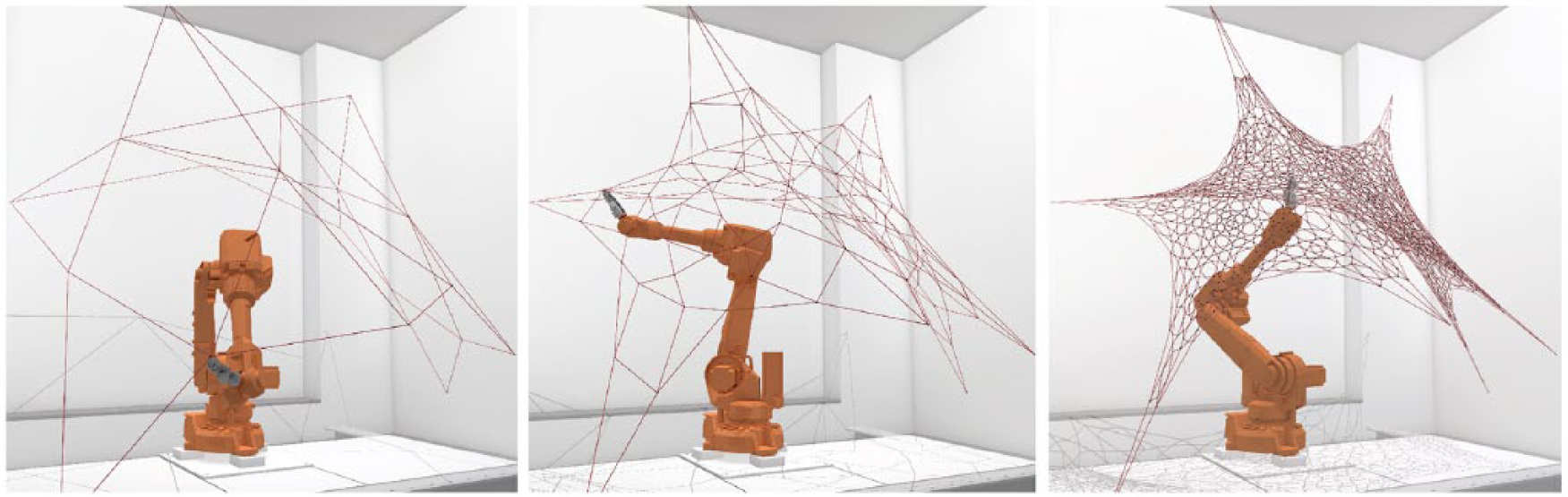
Robotic simulation steps in a case study of mesh structure development. 11
This work follows the previous investigation done by authors and involves parametric control and form-finding process of a three-dimensional surface using Grasshopper 12 plug-in for Rhino 13 and physics-based Kangaroo plug-in 14 for Grasshopper, respectively. The aim is to modify the static system consisting of elastic threads and to generate a tensile structure. An important aspect in the design of elastic mesh system is the balancing of tensile forces that prevents the development of loose threads. Thus, during the simulation process, pretension forces are exercised on the threads that cause overall distortion and normalization of grid structure.
The restrictions related to the use of elastic material during the robotic manufacturing process and the limitations that occur during the material modeling using particle-spring behavior15,16 lead to the introduction and development of a multi-objective optimization process based on genetic algorithms. 17 The optimization uses static and construction parameters 5 and restrictions arising from the capacity of the end-effector tool to handle the material. Through the process, a population of best solutions is generated. The Pareto front suggests a series of best solutions followed by the selection of desirable ones by the architect-user aiming at feasible construction.
The manufacturing process is based on the development of the tool-path that is the result of the progressive deformation of the elastic material system and the addition of threads during the construction process. In this case, thread’s material characteristics and connections influence the design of the end-effector tool. Technical characteristics such as time, precision, and forces for handling the silicone elastic threads are feeding the digital process. The overall behavior of the end-effector as well as of the robot is the result of digital optimization process. In order to evaluate (Figure 2) the results derived during the digital optimization process as well as their effect on the actual construction of tensile system using silicone elastic threads, the proposed scenario involves capturing the node position using camera devices and transferring the information into the digital environment. 18
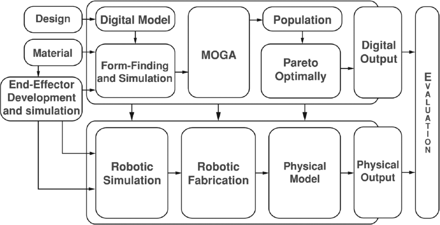
Diagram of the suggested methodology applied in this work.
Through the suggested real-time manufacturing process, the possibility for developing complex morphologies influenced by decisions taken by architects was examined in order to optimize the respective construction outcomes. The suggested fabrication process is achieved by a number of necessary steps that are taken into consideration:
Geometrical development and multi-objective optimization;
Research on the adaptive control of robotic arm behavior and generation of fabrication tool-paths;
Development and simulation of the end-effector tool.
Geometrical and tool-path development through optimization
Initially, this research work explores eight different families of best tensile mesh solutions through the design of surfaces with different Gaussian curvatures, their investigation in regard to the deformation of elastic threads, and finally, the position of their anchorages. The purpose is to evaluate the results based on static performance criteria and construction constrains, leading to the robotic manufacturing of appropriate ones. Important aspects for the typological development of the structural systems are the capability, the precision and the scale of the end-effector tool in order to effectively handle the given material. As the continuous motion of the robotic arm determines the initial morphology of the nodes and lines of the tensile mesh system, the simulation, the analysis, and the multi-objective optimization of the morphology intend to control the tensile forces and to create construction data for robotic control.
The investigation of the initial geometry and the modification of the solutions in each family of tensile meshes are performed parametrically by defining the size of the surface, the space y that is the distance between curves determining the surface, and the value x that is the length of each curve and in this case is y = x = 1 m. The density of nodes is designated by the division parameters P and D, where in this case is fixed at 11 divisions. The parameter P is specified as the integer division of the two curves in equal parts creating nodes that are connected via lines. These are defined as rigid cables with two anchor points at their start and end. The mounting of points PAi and PBi on the rigid cables is defined by the parameter Ai and Bi and consists of values from 25% to 75% of the distance between subdivisions. The respective opposite anchorages PAi and PBi are connected by lines Li, which define the primary length of elastic threads. The subdivision of the primary elastic threads Li with the integer value D aims to create points P that are weave-like connected to create triangulations between the primary elastic threads Li. Analytically, the weaving rate leading to the creation of lines between two points is described by the ongoing relationship Li (Pa), Li−1 (Pb) and Li−1 (Pb), Li (Pan), where a = 0, 2, 3, 4, … n and b = 1, 3, 5, 7; it applies to each line and is shown in Figure 3. The process is repeated until i−1 = P, leading to the final results that represents the initial geometry of the tensile mesh system.
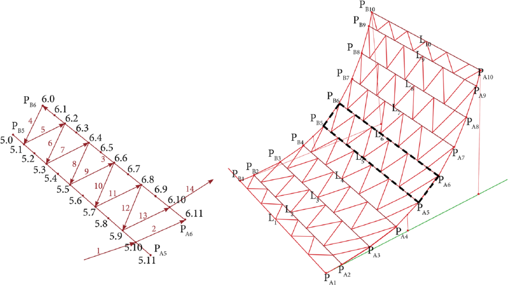
Wave sequence of the silicone elastic threads.
The form-finding process for the creation of the progressive tool-path in the form of weave-like pattern, the modification of curvature, and the determination of maximum permissible value are achieved in digital design environment through the simulation of each case separately. The simulation is accomplished using the particle-spring behavior modeling in Kangaroo plug-in for Grasshopper. For simulating the deformation and for calculating the forces that are the results of pretension of threads due to the use of the end-effector tool, physical experiments and digital verification of modulus of elasticity of the material K are determined as K = 50 N/m.
Subsequently, the ability of the end-effector tool to weld and control the length of threads is determined by the initial length of elastic threads, which is described as the length/distance ratio L/D with values from 70% to 100%. By modifying the initial length of threads, tensile forces are induced causing deformation of each thread and of the overall tensile system. The parametric definition of the length of threads and the position of joints are considered determinants of the final results, requiring parallel verification based on manufacturing criteria such as balance of tensile forces, zero compressive forces, minimum tensile strength, and overall quantity of the material used.
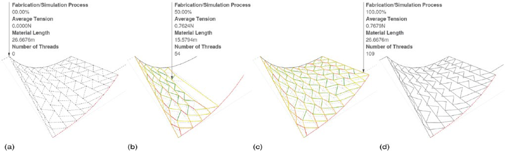
The use of multi-objective optimization process via genetic algorithms allows handling of a number of multiple criteria and parameters leading to a range of acceptable and close to the optimum results. For optimization purposes, the Octopus optimization engine 19 (plug-in for Grasshopper) is applied. The continuous alternation of the anchorages and the length of initial threads are simulated in Kangaroo plug-in, developing a population of acceptable solutions associated with the tensile forces, the amount of material used, the deformation of material, and the capabilities of the suggested end-effector tool. The selection of best solutions based on their tensile performance behavior and the length of threads is achieved through the use of the Pareto front (Pareto optimality) (Figure 4).
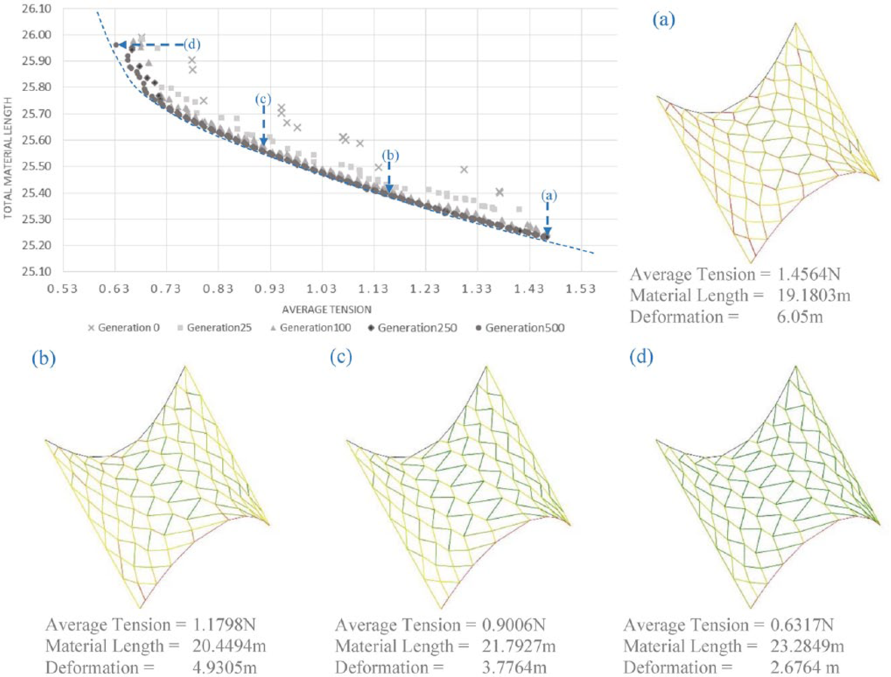
Results derived from the multi-objective optimization process: (a) Best static behavior result, (b) Optimum static behavior result, (c) Optimum geometrical configuration result, and (d) Best geometrical configuration result.
Analytically, the parameters of anchorages Ai and Bi and the ratio thread L/D are considered the genotypes that change in each generation. The anchorages Ai and Bi are changed from 25% to 75% of the position of the rigid parts of the structure and from 70% to 100% of the initial distance. The two parameters affect the results of simulation that are examined according to their static performance by associating the modulus of elasticity and the deformation of the overall tensile system. A fundamental fitness value maintains the tensile forces of the system more than N = 0.15 N, wherein, based on the modulus of elasticity, this is related to the accuracy of the end-effector tool for thread control with ±0.003 m divergence. The best results formulate the population of solutions in each generation and are evaluated based on the reduction of the average tensile force and the total length of the deformed threads. The deformation of threads, the length amount of threads required, the tensile forces, and the curvature are the criteria to evaluate the static performance and constructability of structure in each case through generations and according to the family of typologies under investigation.
In each family of typologies, the multi-objective optimization process is run, producing a range of possible results that are distinguished into two categories for selection by the architect-designer and then physically construct using robotic technology:
Optimum results based on their static behavior;
Optimum results based on their geometrical configuration.
Regardless of the selection of solutions for construction purposes, the geometrical results are translated into tool-paths used for robotic motion behavior through the parallel simulation of the progressive form-finding process.
End-effector tool development
As it has been mentioned, this work mainly focuses on the development and simulation of the end-effector tool (Figure 5), which is considered to be a fundamental element of the overall fabrication process since it is responsible for the elastic material handling and hence the results of construction. Specifically, through the continuous addition of elastic threads, the welding, and, finally, the node creation, the construction of tensile mesh can be achieved.
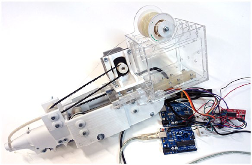
Physical prototype of the end-effector tool.
Within this framework, an initial investigation into the production of tool’s physical parts using trial-and-error methods of fabrication is introduced. The process of adding elastic threads based on specific geometric rules results in the formation of mesh systems consisting of edges and nodes. As part of the welding procedure, the bonding of threads is achieved by the use of a hot-melt adhesive. Based on the observations derived from the experiments and the elastic threads control requirements, a multipurpose end-effector that involves three operations is proposed:
Length control and elastic thread feed;
Supply and hot-melt adhesive;
Holding and creation of nodes.
Design and control of the end-effector tool
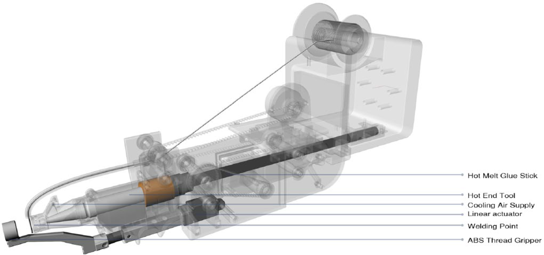
The proposed end-effector tool consists of three actuators that control its mechanical and movable parts and are responsible for the operational procedures mentioned above. Through synchronization and calibration of operational steps, the overall handling process is achieved. The design of the end-effector tool is influenced by the size of actuators, the scale of material handling, the welding of silicone elastic threads, the base of mounting on the robotic arm (axis J6), the size occupied by the movable parts, and, finally, the scale of the overall mesh structure (Figure 6).
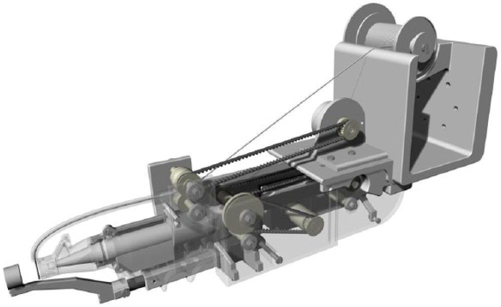
Detail of the end-effector tool.
Length control and elastic thread feed
The aim of length control and elastic thread feed process is the accurate control of the thread’s movement from the bobbin part until the welding spot. The length control of elastic thread is an important part in the development of physical model since it defines the extension that causes the local thread deformation.
Thus, for this operation, a bipolar stepper motor (1.8° steps) is introduced. At the end of motor, a three-dimensional (3D) printed pulley 15T is placed, in which its rotation is transferred to a similar type of pulley that is connected with the poly(lactic acid) (PLA) roller. The full circumference (360°) of the stepper motor is equal to the complete rotation of rollers. Their rotation corresponds to the length of thread necessary to be fed depending on different cases. The material bobbin is mounted to the back and upper part of the end-effector for easy access by the architect-user. Thus, the rollers pull and unwind the elastic thread from the bobbin and feed the PLA cylindrical tube, which in turn transfer the thread to the welding spot (Figure 7).
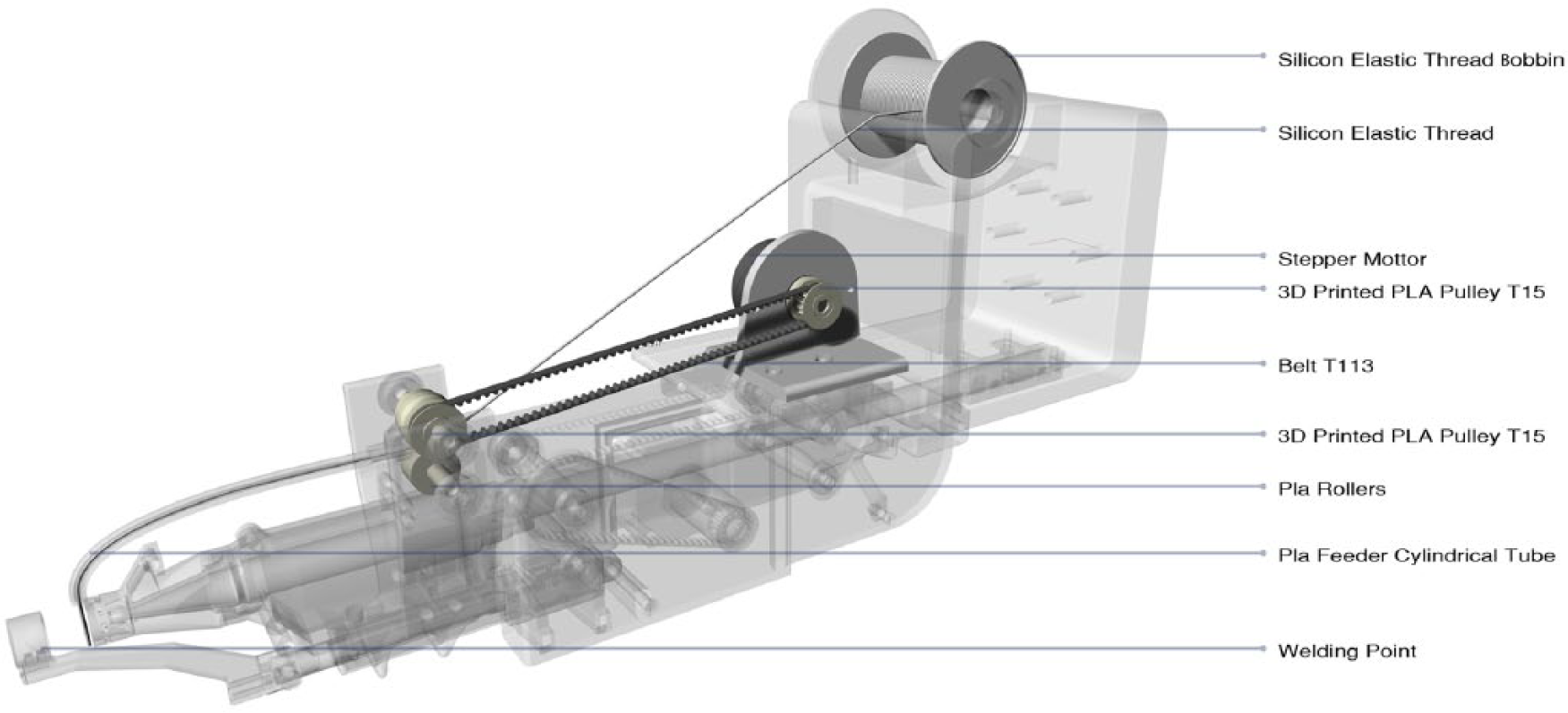
Detail of length control and elastic thread feed.
Supply and hot-melt adhesive
For the welding of threads and the creation of expected nodes, the hot-melt silicone adhesive technology is applied. Due to the same type of silicone material used, both for elastic threads and for hot-melt glue stick, this technology is considered ideal for the creation of nodes/connections. The expected evaluation of the final prototypes as regards the recording of nodes via a vision system requires the use of hot-melt adhesive tube in black color. The supply of hot-melt glue stick (11 mm) is achieved via the use of a stepper motor. The rotation of stepper motor and its connections with the 3D printed pulley 15T causes the transfer of motion via belt to the 3D printed pulley 30T. The increase in pulley’s size allows the reduction of rollers’ rotation relative to the rotation of the servo as well as the increase in the rotational torque generated by the rollers. For the better control of the supply of hot-melt glue stick, the rollers are connected to an additional pulley that transfers the rotational movement via the 3D printed pulley 15T in rollers (this appears on the back side of the end-effector). In order to maintain the correct direction of movement for the hot-melt glue stick, a PLA tube is designed that allows the material to move into and feed the melting apparatus. In this way, the rotation of four rollers pushes the material into the machine for melting purposes. This converts the solid material into liquid at 180°C, which is poured in the hemisphere in the hot end of the end-effector tool for welding the elastic thread material and for creating nodes (Figure 8).
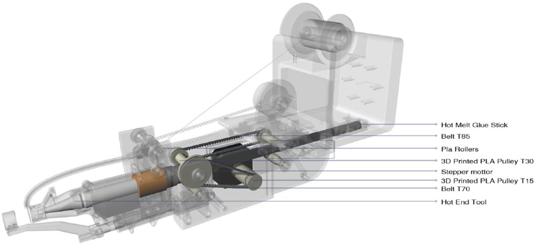
Detail of supply and hot-melt adhesive.
Holding and creation of nodes
An important feature in the process of creating nodes and controlling the threads’ length is the technique for approximation positioning and holding. The retention of elastic thread is found to be necessary in order to reduce failures caused by the pretension of the filament as well as the elevated temperature due to the hot-melt adhesive process.
To control the holding procedure, a linear actuator is used. The design and printing of a 3D prefabricated gripper in front of the end-effector tool manages to control the approximation of thread in the predetermined level and to hold the material. In order to achieve this, the gripper tool includes a hemispherical shape. When closing the linear actuator, the projection moves linearly in the vertical plane of the melter device to hold the thread and create the node. In parallel, by opening the valve, coolant is pervaded in the hemispherical gripper, accelerating the cooling of the node from 180°C to −20°C. With the opening of linear actuator, the node is released, activating the elastic behavior of thread. Finally, the end-effector tool is withdrawn from the welding spot (Figure 9).
Detail of holding and creation of nodes.
Fabrication of the end-effector tool
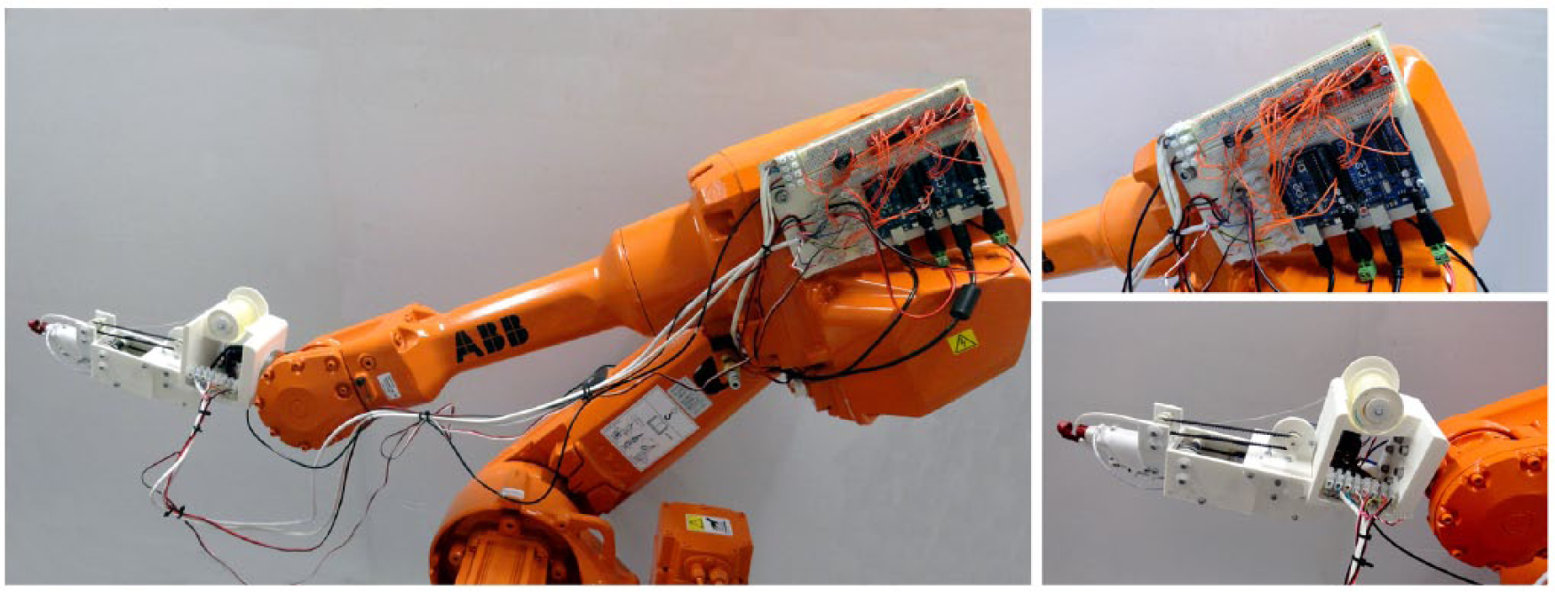
The mechanical parts that make up the end-effector are fabricated on a 1:1 scale and their motion is optimized through trial-and-error testing (Figure 10), aiming at the finalization of the overall physical prototype. In particular, the end-effector is divided into three discrete parts:
Electronics and material case;
Mechanical and actuator case;
Melting and adhesive component.
Physical prototype of the end-effector tool.
The fabrication of the prototype is achieved through rapid prototyping and specifically through 3D printing using poly(acrylonitrile butadiene styrene) ABS and PLA materials. All cases for electronics and mechanical parts are designed and printed, then assembled together, and, finally, connected to the actuators. For material feed, a prefabricated PLA roller is introduced. The rotation of rollers is achieved in combination with the timing belts, which convey the motion from the actuators to the rollers.
The electronics, the cooling air valve, and material part are fixed at the end of the robotic machine. This part includes all the electronic components of the end-effector including connecting cables for actuators, power supply, and Arduino board. Also, in this section, the placement of materials (silicone elastic thread and glue stick) and their feeding control through the actuation of kinematic mechanisms can be found. For better self-weight distribution of the end-effector the stepper motor that is responsible for the length control and material feed process is placed close to the end of the robotic machine. Then, the mechanical and actuator case is adapted and screwed into the bottom of the electronics and material case. At this part of the end-effector rotary actuators and mechanical details (pulleys, belts and rollers) that are responsible for the supply and hot-melt adhesive operations can be found. Also, this section incorporates the linear actuator that is responsible for the holding and node creation process. Finally, the melting, cooling, and adhesive components are added and screwed in front of the mechanical and actuators’ case consisting of three parts. The first part represents the case for the melter that is used for supply and hot-melt adhesive process. In the front area, the cooperation with the linear actuator achieves the accomplishment of the holding and node creation process. The second part is connected to the first part, and it bears all mechanical details, that is, pulleys, rollers, and PLA tube for the length control and elastic thread feed process. The final part is responsible for spraying the first part to reduce the temperature in each node, obtaining the smelting reduction of node from 1.3 min to 5 s (Figure 11).The three main parts are connected together so as to control and synchronize the whole procedure. In addition, the separation of parts enables to redesign the parts in order to optimize the motion behavior and improve the mechanical details.
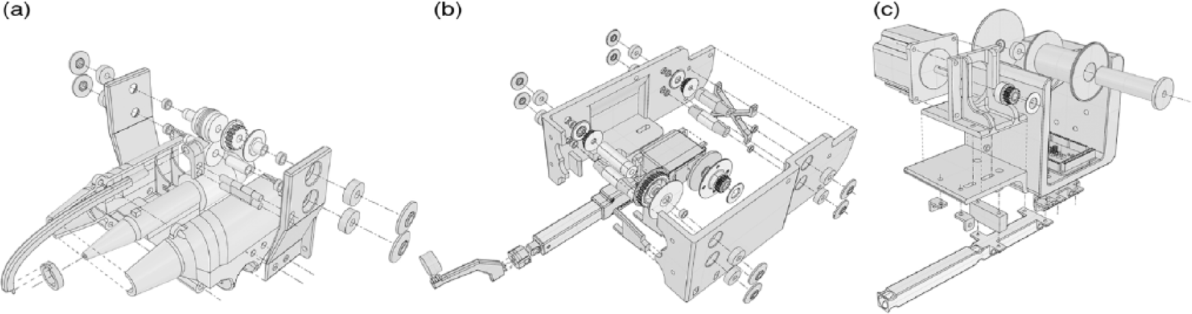
End-effector parts: (a) melting and adhesive component, (b) mechanical and actuator case, and (c) electronics and material case.
Programming and control
To program the mechanical parts, the Arduino board that is linked to Grasshopper via Firefly (plug-in for Grasshopper) 20 is used. Two programming tasks responsible for the control of the end-effector are distinguished:
Creation of the start node;
Length control of elastic thread.
The two tasks are responsible to control the information from the digital model, activating the respective movement of actuators. Initially, to develop the control algorithms, the actuators are connected to the Arduino board. Because the stepper motors need to receive data in pulses, two Easy stepper driver boards that are connected to the Arduino board are used. The stepper drivers are responsible to control the data from the Grasshopper to the stepper motors, controlling, in parallel, the direction and angle of rotations. The control of linear actuator is achieved by the use of a simple three-pin wiring. With the use of numerical values 0°–180°, which are designated in Grasshopper and transferred to the Firefly writer, the lengthening of the linear actuator is defined (Figure 12).
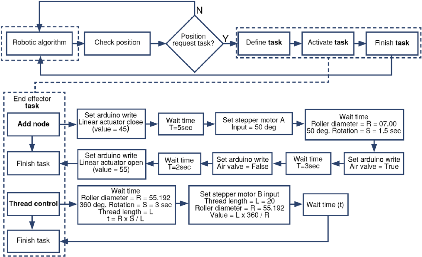
Diagrams describing the functions of the three tasks.
Initially, actuators are calibrated in relation to the rollers of operations. For the length control and elastic thread feeding procedure, a full rotation (360°) of stepper motor equal to the perimeter of roller (55.2 mm) is introduced, which achieves respective thread feed. The supply and hot-melt adhesive procedure is achieved by the rotation of the second stepper motor. Specifically, a time interval of 5 s is required for pushing the expected glue stick and for creating the node. In front of the stepper motor, a gear 15T is mounted, wherein by rotating and moving the belt it rotates a gear 30T. The gear is connected with a roller of 14 mm diameter that rotates and achieves to power the glue stick. By reducing the rotation from the stepper motor to the roller in half, 50° of rotation is required. Finally, to control the linear actuator in the holding and creation of node procedure, a numerical value of 40° opens and a value of 55° releases the node.
For the robotic motion control, the HAL (plug-in for Grasshopper) 21 is introduced and synchronized with the actuation of the end-effector tool. By using feedback loop logic between robotic machine and the HAL software, the algorithm is responsible to control and determine the order of elastic threads’ addition. Each thread is added by using the two tasks described above.
The task programming occurs by calculating the time duration depending on the position of the robotic machine. Initially, the algorithm for controlling the node creation activates the opening of the linear actuator. Subsequently, the activation of the stepper motor manages to feed the welding spot (Figure 13(a)). Then, the linear actuator slightly closes in order to hold the threads (Figure 13(b)). Parallel to the complete closure of the linear actuator, the stepper motor is activated to feed the hot-melt glue stick (Figure 13(c)). This is liquefied using the melter and the threads are adhesive for node creation. In parallel, the air valve is opened to supply cooling gas and hence reduction of required melting time in each node (Figure 13(d)). Finally, by opening the linear actuator, the robotic machine is withdrawn and continues its motion (Figure 13(e) and (f)).
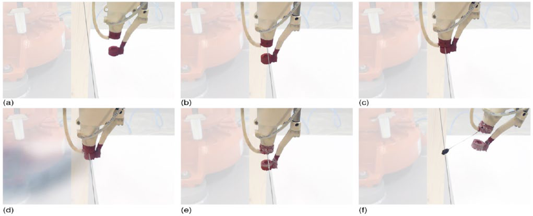
Node creation process: (a) end-effector approaching, (b) linear actuator closing, (c) hot-melt glue stick liquefied, (d) node cooling, (e) linear actuator opening, and (f) end-effector withdrawal.
Parallel to the relocation of the robotic arm from the start node, the task for controlling the length of thread is activated (Figure 14(b)). This procedure aims to supply, in each case, the required length of elastic silicone thread. The suggested algorithm checks the result of tensile structure simulation and sets the required length of thread in order to achieve the desirable pretension and deformation of the mesh structure. The defined length is translated into an angle used for stepper motor rotation that causes the release of expected material. The time of rotation is calculated and compared to the time needed by the robotic arm to move from the start to the end node. If the time needed for length thread wrapping is longer than the time needed for the robotic arm movement, the robot waits to execute the task for a respective time and then continues the node creation procedure (Figure 14(a) and (b)). Then, the control algorithm specifies new coordinates in which the silicone elastic thread addition procedure will occur.
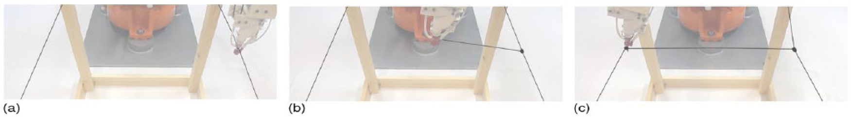
Thread control process: (a) first node creation, (b) thread control from the end-effector, and (c) second node creation.
The initial tool-path based on the form-finding process and the data derived from the ratio L/D as well as the position of anchorages arising from the optimization process result in the creation of best tensile systems in terms of their structural and construction performances. For the construction of tensile mesh, the continuous refinement of tool-path is required due to the deformation of the whole system in every node addition. The redefinition of the tool-path and the robotic manufacturing process occur in real time and is achieved through the parallel simulation of the gradual addition of threads for tensile mesh production. Analytically, the end point Pi of the current line Li, which is under construction by the robotic arm and is simulated through the Kangaroo plug-in, is linked with the next point Pi + 1 of the next added line Li + 1. The new point Pi + 1 is sent via streaming to the HAL plug-in, and consequently, the addition of Li + 1 is simulated. With the addition of the new line in the system, the simulation redefines the overall structural system under construction. At the same time, the rate L/D is used to generate length per line that is sent to the end-effector tool for execution. The prescription of the information related to the control of the robotic arm and the end-effector tool results in the automation of silicone elastic thread manufacturing process (Figure 15).
Tool-path simulation—refine process: (a) initial tool-path, (b) and (c) refine tool-path/material behavior, and (d) final tool-path.
Conclusion
In this ongoing research, the design and physical development of an end-effector tool is presented, which is able to add material of elastic threads on mesh systems, aiming at the gradual construction of tensile structures. This becomes necessary when the objectives involve the construction of complex morphologies using materials with elastic properties, a task that, in comparison with the traditional fabrication of shapes using CNC mechanisms, requires the introduction of advanced construction systems in order to achieve precision as well as elimination of deviations due to deformation of the structures during the construction process.
The use of mechanical parts and actuators as well as their programming control enables the development of a custom-made end-effector tool with specific fabrication abilities defined according to the construction task under investigation. The tool plays an important role in the suggested robotic manufacturing and automation process. Toward this direction, three operational steps are applied, which can be evaluated according to the quality of the result achieved due to the required highly accurate process of thread installation and node creation. Therefore, the results of construction are directly related to the decisions taken at the digital design level as well as at the level of programming and control.
In addition, the recent advancement in the area of real-time control and simulation 22 enables the robotic machine and elastic structure behavior simulation, as well as the activation and deactivation of the custom-made tool. The possibility for a direct relationship between the architect-user and the digital environment is extended to allow simultaneous connections with the manufacturing process, whose results are affected by a design optimization process using genetic algorithms. At the same time, the architect-user is able to make decisions and select the desirable design for construction based on the results obtained during the process.
Further research will concentrate toward the physical performance of the proposed end-effector mechanism. This will be achieved by testing the tool in a series of experiments on a one-to-one scale. Additional directions of investigation will include the transfer of structures’ physical behavior to the digital environment in order to evaluate the robotic movement in a continuous iterative process, enabling accuracy during manufacturing of tensile mesh systems. The comparison and evaluation of digital and physical prototypes will allow the application of specific procedure in the construction of other structures using similar material behavior. The possibility for simultaneous simulation and handling of elastic materials during the robotic construction process allows further exploration that might lead to the construction of complex lightweight structures with minimal materials at a larger scale.
Footnotes
Declaration of conflicting interests
The author(s) declared no potential conflicts of interest with respect to the research authorship, and/or publication of this article.
Funding
The author(s) received no financial support for the research, authorship, and/or publication of this article.