



Abstract
Shape-changing materials have become increasingly popular among architects in designing responsive systems. One of the greatest challenges of designing with these materials is their dynamic nature, which requires architects to design with the fourth dimension, time. This article presents a study that formalizes the shape-changing behavior of three-dimensional printed wood-based composite materials and the rules that serve to compute their shape-change in response to variations in relative humidity. In this research, we first developed custom three-dimensional printing protocols and analyzed the effects of three-dimensional printing parameters on shape-change. We thereafter three-dimensional printed kirigami geometries to amplify hygroscopic material transformation of wood-based composites.
Keywords
Introduction
Shape-changing materials are smart materials in which a stimulus (i.e. humidity, heat, light) creates a strain and actuates shape-change in the material. These materials have embedded natural sensors and actuators, and do not require any mechanical or electronic control for shape-change. Research on these materials, however, have mainly been conducted in areas other than design, such as materials science and engineering, and have only recently started to permeate design practice and research.1,2
One of the greatest challenges of incorporating shape-changing materials into design fields is the lack of methodological frameworks for designing with the dynamic behavior of these materials. As Kennedy 3 points out, designing with shape-changing materials entails incorporation of time, the fourth dimension, into design practice. On the contrary, shape-changing behavior is usually unpredictable at the beginning. While unpredictability can give way to unexpected discoveries and emergent material outcomes that can enrich the design process, it is necessary to understand how they occur to gain control over the dynamic nature of shape-changing materials.
In this article, we present a research in which we three-dimensional (3D) print wood-based composite materials that change their shape in response to varying levels of humidity. It is part of a broader research agenda to design responsive architectural skin systems that change their shape in response to environmental stimuli, without additional electronic or mechanical control. Wood is a naturally hydro-responsive material: it swells and contracts in response to changing humidity levels. As we show in this article, 3D printing with wood allows to design custom hydro-responsive material transformations. However, there are many parameters that affect these material transformations, and they are causally interrelated. In order to have control over this shape-changing behavior, it is necessary to first systematically study the effects of these parameters on material transformations. In this research, following a bottom-up approach, we first developed 3D printing protocols that let us customize tool paths for 3D printing wood-based composite materials. We actuated the 3D printed wood-based composite samples in controlled humidity chambers and systematically analyzed the effects of 3D printing parameters on their shape-change. This enabled us to generate a set of rules that formalize tool path generation and shape-change of 3D printed samples. In the following stage, with the aim to amplify material transformation, we explored applying these rules to more complex kirigami geometries and developed a new set of rules that we called kirigami rules. Using these rules, we 3D printed another set of hydro-responsive wood-based composites, this time with kirigami geometries. Actuating these yielded more complex and amplified hygroscopic material transformations that we captured and documented via 3D scanning.
In the following sections of the article, we first provide a review of the related literature on shape-changing materials in design and architecture, and on formal methodologies to compute material behavior. Following the review, we present the main framework and stages of the study that we mentioned above in more detail. We then present a case study on formalizing the shape-changing behavior of 3D printed wood-based composite materials, that we call 3D printed shapes, and the rules that we developed to compute their shape-change in response to variations in relative humidity. We conclude with a summary of research results and a presentation of the next research stages.
Literature review
The relevant literature is reviewed in two main sections. The first section presents existing research on shape-changing materials and systems that informed our research. In this section, we first provide an overview of various applications for shape-changing materials in design and architecture in order to situate our research in a broader context. We then focus on the existing research on shape-changing architectural skin systems that employ hydro-responsive wood components, including research on 3D printed hydro-responsive wood that have set a basis for our case study on 3D printing wood-based composites. We conclude the first section by reviewing the studies that incorporate kirigami geometries to shape-changing systems. These studies led us to explore 3D printing kirigami geometries to amplify shape-change of wood-based composites. In the second section, we review existing formal methodologies to compute material behavior in design. Focusing on shape grammars, a formalism that can handle uncertainties in visual computation, we present the existing studies that aim to extend shape formalism from visual processes to material processes. These studies guided us in developing the rules to formalize the shape-changing hydro-responsive behavior of 3D printed wood-based composites. We conclude this section by reviewing the studies that focus on capturing and analyzing shape-changing material transformations.
Shape-changing materials in design and architecture
A growing body of literature investigated ways to incorporate shape-changing materials into dynamic architectural systems. The literature includes studies using several shape-changing materials such as shape-memory alloys,
4
thermo-bimetals,
5
shape-memory polymers,
6
and wood.
7
In these studies, researchers explore not only how to incorporate shape-changing materials into architectural systems but also how to design and fabricate the shape-changing materials themselves, since, commonly, these materials are not commercially available as ready-made actuators. Consequently, research addressing the development of shape-changing systems in design fields usually engage in a process of iterative development and testing of materials in which the actuator is characterized. This approach of developing responsive materials within design fields, according to Sung,
5
is in the middle ground between scientific studies and traditional design processes: A traditional scientific inquiry intentionally eliminates as many variables as possible in order to focus on a single solution that can be replicated over and over again, while the architectural design process deals with numerous variables that eventually contribute to the uniqueness of each design. (p. 106)
One can argue that research on shape-changing materials in architecture dwell in between scientific rationale and the qualitative value of constructing meaningful and aesthetically pleasing designs.
Two of the most popular fabrication techniques employed in research to develop shape-changing materials are bilayering and 3D printing. In a bilayer configuration, two tightly attached layers that have differential thermal expansion or swelling tend to bend when actuated. In architectural applications, a bilayered technique has been used to fabricate shape-changing materials with thermo-bimetals8,9 and wood.10,11 The second strategy, 3D printing, also entails constructing bilayers, but this time by 3D printing the layers. More complex material transformations can be obtained by embedding anisotropy through changing the 3D printing parameters (i.e. bead center distance, speed, temperature, materials) of layers. This approach of tool path design for manufacturing responsive materials can be seen in research on soft materials 12 and self-assembled systems. 13
Among various shape-changing materials, wood is extensively used to construct responsive architectural systems. Wood is a natural fiber-reinforced composite material that is naturally responsive to humidity. While this hygroscopic behavior is typically not considered favorable in the building industry, researchers have made use of this humidity-responsive behavior to develop shape-changing architectural systems.7,14 Moreover, the microstructure of wood, namely, the alignment of the fibrils, can be configured and designed to create large-scale shape-changing systems, as recently shown in a study by Wood et al. 15 As previously mentioned, one common strategy for fabricating shape-changing components with wood is through bilayers, where layers with differential swelling behavior bend when exposed to humidity. Therefore, by designing the arrangement and orientation of layers, one can embed a programmed response into the material. Studies using the bilayer principle have mostly relied on the use of wood veneer and designed the orientation of the fibers in different layers to achieve a desired transformation mechanism. The literature includes the development of an autonomous shading system made with humidity-responsive wood bilayers, 11 an hydro active skin and cladding system, 14 and large-scale bilayer surfaces for self-assembly of architectural elements. 16 Recently, researchers explored 3D printing as another strategy to develop shape-changing wood actuators. The extrusion process in 3D printing results in the alignment of the wood fibrils that are present in bio-composite filaments in the direction of 3D printing through fused filament fabrication. 17 Therefore, the control of material deposition tool paths and 3D printing settings can be used to design localized swelling in 3D printed wood-based composites. In a recent study, Correa et al. 18 have 3D printed responsive systems combining wood filament with non-responsive polymers such as ABS and nylon. The main advantage of 3D printing approach over bilayered materials is that additive manufacturing allows producing more complex shapes and microstructures that can have tailored responses to humidity.
One important challenge that we see in incorporating shape-changing materials in architecture is the relatively small transformation that these materials present in relation to the scale of application. One of the ways to amplify transformation mechanics of shape-changing materials can be to integrate kirigami and origami techniques into the design and fabrication of responsive structures. Kirigami and origami techniques allow to transform flat surfaces into complex three-dimensional geometries and can be used to develop advanced materials. These craft techniques have been sources of inspiration for a wide range of engineering applications that include solar tracking systems and deployable structures.19,20 Ning et al. 21 provide an overview of this emerging area of research that utilizes folding and cutting techniques, and Sorguç et al. 22 review the use of these techniques in the design and fabrication of architectural systems. While in these applications, material transformation is actuated manually or electronically, recent studies also explore the use of shape-changing materials as a means to actuate material transformation in kirigami and origami-inspired systems without the need of an electronic or mechanical control. Pesenti et al., 23 for instance, combined origami techniques with shape-memory alloys, a thermo-active material, to design a responsive shading device. Similarly, Yi et al. 24 proposed the use of kirigami geometries with thermo-active shape-changing materials for shading devices.
Formal methodologies to compute material behavior in design
Formalizing enables to express a process in a formal way, such as an algorithm. Being able to formalize a process indicates a deep understanding, and it enables not only to repeat and create controlled variations but also to communicate this understanding with others. Since its introduction by Stiny and Gips 25 as a computational theory, shape grammars offer a formalism for representing seeing and visual thinking in design and for establishing a common ground to talk about design as a visual reasoning process. Rules in shape computations formalize the exploratory process and enable systematic and creative exploration of design spaces. On the contrary, design explorations do not rely only on visual aspects. There are creative design processes that feed from making and material behavior, as in the case of designing with shape-changing materials. This kind of processes in design require extended formalisms that can integrate visual, spatial, and material reasoning. With the aim of exploring the possibility of computing material behavior in design, “material shapes” have been previously introduced in shape computation as part of a dialogue between abstract representations and their material outcomes. 26 Along similar lines, Knight and Stiny have explored the possibility of extending the shape grammar formalism from shapes to “material things” with “making grammars.” 27 In this article, we present a case study in which we 3D print wood-based composite materials using hygroscopic wood-based filaments. With the aim of formalizing shape-changing behavior of 3D printed wood-based composites in response to humidity, we integrated material transformations of hydro-responsive 3D printed samples, that we call 3D printed shapes, into shape computing. In the context of this article, formalizing corresponds to defining shape rules to (1) generate 3D printing tool paths that guide the fabrication of 3D printed shapes—fabrication rules, (2) represent the shape-changing response of 3D printed shapes to humidity—shape changing rules, and (3) generate 3D printed shapes based on kirigami geometries—kirigami rules. We argue that these rules set a basis to design hydro-responsive architectural skin systems by 3D printing wood-based kirigami geometries.
To accurately document shape-change, researchers have made use of two main strategies: employing image analysis techniques and embedding sensors in shape-changing materials. For image analysis, some researchers placed a square or radial grid 7 or curvature charts 10 behind the shape-changing materials and took photos (or videos) of the materials at regular intervals. These grids or curvature charts serve as references while analyzing material transformation through images. There is also software that can compare still and moving images by tracking the changes of color markers placed on the samples. Rüggeberg et al., 28 in their study on hydro-responsive wood systems, used a free image analysis software called ImageJ, which allowed them to track the bending transformation of the samples that they test. Similarly, Abdelmohsen et al. 29 used another free image analysis software, Kinovea, that enabled them to compare and analyze moving images to track the hygroscopic shape-changing behavior of wood samples. It is also possible to develop custom computer vision algorithms to capture and analyze shape-change, as in the research by Baseta. 30 She has generated a code that extracts and compares the position of colored parts, in this case, the colored boundaries of the samples. Embedding sensors in shape-changing materials is another strategy to capture and document shape-changing behavior. Some researchers developed physical computing systems with flexsensors and Arduino to make 3D digital models that got updated following the shape-change in the samples where the flexsensors were attached. 29 This system is limited to two-dimensional and unidirectional motion and could not sense 3D motion such as twisting. There are also expensive sensors that are commercially available that replicate changes in the shapes of real objects in the digital environment using fiberoptic sensing technologies. In this research, we used an image analysis strategy to document the hygroscopic material transformations of 3D printed shapes. We used a grid in the background and took snapshots at regular intervals to later superimpose and compare the images using image editing software.
Research framework and stages
In this research, we followed a three-step exploration, as illustrated in Figure 1. The process begins by defining a framework that identifies the parameters for bottom-up material exploration. These are design, fabrication, and material parameters. The next step is to conduct a material exploration by fabricating a series of prototypes by systematically changing one parameter at a time and testing them. Testing, in the context of this study, corresponds to actuating the 3D printed shapes in controlled humidity chambers and documenting their hygroscopic material transformations. This material exploration stage involves cycles of translating digital/abstract representations to material things, in our case through 3D printing using wood-based filaments. Finally, the findings from these cycles are formalized through rules and/or algorithms in order to inform subsequent design processes that involve top-down explorations.
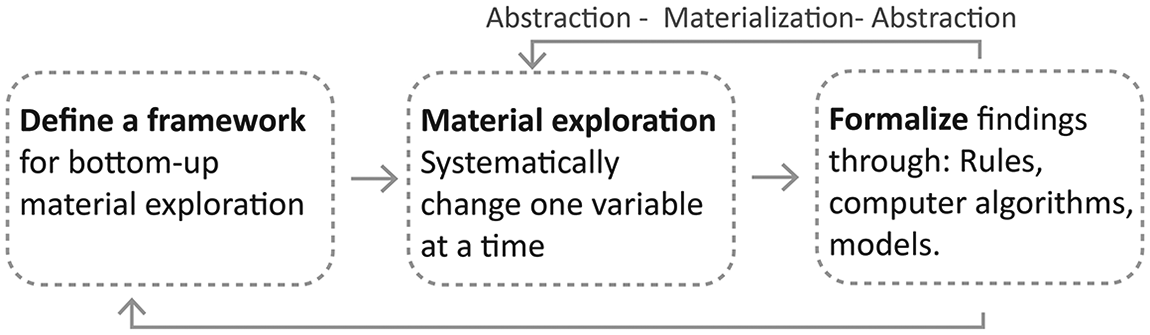
Research stages.
The framework that we defined for bottom-up material exploration is shown in Figure 2 and was presented in detail by the authors in a previous publication. 31 As mentioned above, this framework identifies the parameters for material exploration and can be grouped under three main categories as parameters to (1) design the base geometry and the geometry of 3D printing tool paths, (2) materialize the tool path designs by 3D printing using different materials and print settings, and (3) actuate the 3D printed shapes over time under different temperature and humidity levels.
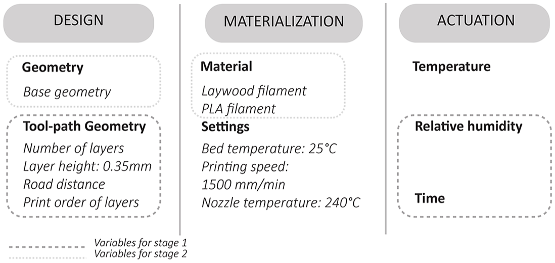
Framework for bottom-up material explorations.
In the following section, we present the case study on 3D printed wood-based composites in two stages: the development of initial prototypes through which we gained control over the design of 3D printing tool paths that condition shape-change, and a follow-up exploration in which kirigami geometries were used to amplify hygroscopic material transformation. In the first stage of this study, we systematically changed the parameters for tool path geometry and the actuation conditions (except temperature), while keeping the base geometry and materialization parameters constant. The learnings from this first stage informed the second stage, where we systematically changed the base geometry and the 3D printing materials in order to explore hydro-responsive behavior of 3D printed kirigami geometries.
Case study on 3D printed wood-based composite materials
Transitions between abstract representations and material things in an “abstraction–materialization–abstraction cycle” are key to design processes that involve material explorations. 26 This is particularly relevant in designing with shape-changing materials, which demands an iterative process of development and testing due to the fact that they are not commercially available materials. These cycles of development and testing are conceptualized in our framework as abstraction–materialization processes. Abstraction stages entail the definition of rules that define fabrication rules for the following materialization cycles and/or capture the outcomes from previous material explorations. During materialization stages, 3D printed shapes become part of the design process. In the case study presented, this involves 3D printing with wood-based filaments using fused filament fabrication. Figure 3 depicts the two consecutive stages of the case study as two abstraction–materialization–abstraction cycles.

Proposed framework.
The process begins by defining rules to generate tool paths for 3D printing. The tool paths are 3D printed using hydro-responsive wood-based filaments to obtain what we call 3D printed shapes. When actuated with humidity in a controlled environment, these 3D printed shapes change. With the aim to formalize the shape-change, transformations observed in the 3D printed shapes are again represented as rules. This constitutes an abstraction where, among many possible material aspects, we choose to focus on the changes in the boundaries of the 3D printed shapes captured through image analysis. As part of the consequent abstraction–materialization cycle, another set of rules are developed, this time to generate tool paths for more complex 3D printed shapes based on kirigami geometries. Generated tool paths are again 3D printed using hydro-responsive filaments and actuated with humidity. Shape-change of 3D printed shapes are once again abstracted, this time through 3D scanning; 3D scanning technology provides accurate abstract/digital representations and captures the shape-change of 3D printed shapes.
Fabrication rules: formalizing 3D printing tool path generation
The first stage of exploration involves defining visual rules to generate patterns for 3D printing hydro-responsive wood-based composites. These tool path creation rules are shown in Figure 4. The rules shown in this article are simplified due to space limitations. The actual rules are more elaborate and generic in the sense that they can be applied locally to different kinds of initial shapes. For instance, for more elaborate versions of rules K1 and K2 (Kirigami Rules), and a detailed depiction of the generation of kirigami geometries, the readers can refer to Gürsoy and Özkar. 26
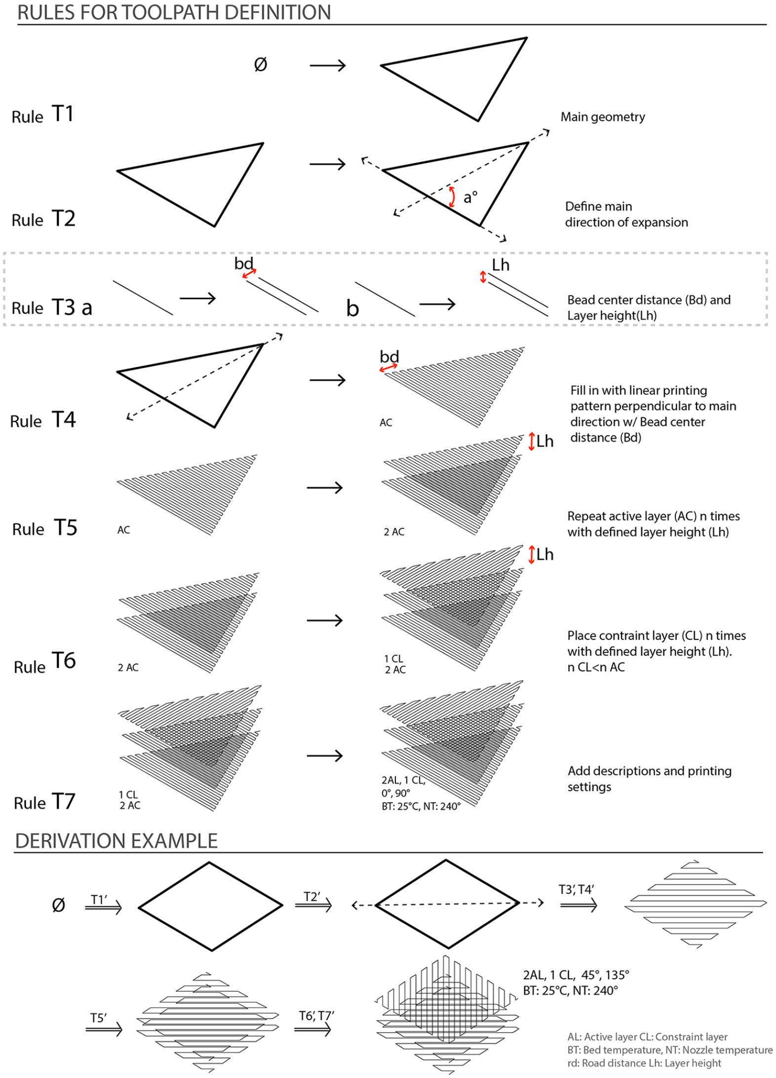
Rules for tool path generation.
Previous work developed in the area of 3D printing responsive systems informed the creation of these fabrication rules. Work by Correa et al., 18 for instance, provided information about the relationships between the main direction of expansion and the main angle of the linear 3D printing pattern. These are formalized in Rules T1, T2, and T4. Rule T1 defines the boundaries of the geometry to 3D print. Rule T2 identifies the main direction of expansion in this geometry and adds a reference line. The direction of expansion can adopt multiple angle values in relation to the main geometry. Rule T4, then, defines the direction of 3D printing pattern of the active layer (AC) as lines that are perpendicular to the reference line emerging from Rule T2. Rule T4 also erases the bounding shape and the reference line. It is a parametric rule: horizontal offset distance between 3D printing pattern lines, that we call bead center distance (bd), can be altered. Research by An et al. 32 informed the active layer (AL) to constraint layer (CL) relationship. In a bilayer configuration, constraint layers trigger shape-change, while active layers define the main direction of expansion/swelling following the direction of the 3D printing pattern. Distribution of constraint layers and active layers considerably affect the resulting shape-change. This relationship is formalized through Rules T5 and T6. Rule T5 defines the total number of active layers to 3D print: it adds copies of the 3D printing tool path of the active layer (shape generated through Rule T4) vertically following layer height (Lh) parameter. Rule T6 introduces constraint layer(s). Constraint layers have 3D printing patterns that are perpendicular to the 3D printing pattern direction of active layers. The number of active and constraint layers can change, but the important condition that must be kept is that the number of active layers should be greater than the number of constraint layers in a bilayer configuration. In other words, the active layer will always recur more in a tool path configuration.
Tool path creation process, thus, follows this sequence: defining the boundary of the main geometry to 3D print (Rule T1), identifying the main direction of expansion (Rule T2), defining bead center distance (bd) and layer height (Lh) parameters (Rule T3a and T3b), generating the 3D printing tool path of the active layer (Rule T4), identifying the total number of active layers and making copies if necessary (Rule T5), generating the 3D printing tool path of the constraint layer and adding constraint layers (Rule T6), and adding the 3D printing settings as labels (Rule T7). Note that Rules T3a and T3b are highlighted in Figure 4 as parametric rules that adjust the overall density of the 3D printed shapes.
The bottom part of Figure 4 shows an example of a derivation of applying variations of these rules to define tool paths for 3D printing of a shape-changing prototype. Notice that the rules are not limited to a specific geometry and can be applied to different shapes. In addition, the 3D printing angle defined by Rule T2 can adopt multiple values, as shown in the derivation example. Tool path definition rules, for the most part, are not material-specific at this point, with the exception of Rules T3a, T3b, and T7. Rules T3a and T3b define the bead center distance (bd) and layer heights (Lh) that are in direct relationship with material conditions of the filament used and the 3D printer. Rule T7 defines the printing settings for the tool path that change according to the material used and its respective tg (glass transition temperature) and tm (melting point). Here, we included the most important printing settings for our experiment: bed temperature and nozzle temperature; however, the complete set of 3D printing settings comprises a much larger list, including traveling speed and extrusion speed. These 3D printing settings are not software specific. Custom g-codes for 3D printing using these settings can be generated in several CAD software. In our case study, we used Silkworm for Grasshopper for this purpose.
From visual shapes to 3D printed shapes
Tool paths generated are 3D printed using a commercially available wood-based filament called Laywood to obtain the 3D printed shapes. Figure 5 shows the abstract shapes side-by-side with the resulting 3D printed shapes that have been kept in humidity chambers with 99% relative humidity for 40 min. We focused on understanding the effects of the 3D printing angle (defined through Rule T2) and bead center distance (defined through Rule T3a) on shape-change; 3D printing settings, such as bed and nozzle temperatures, are kept constant once optimal configurations for Laywood filament are found. For a detailed explanation of the 3D printing parameters, readers can refer to Vazquez et al. 31 Findings indicate that the direction of 3D printing patterns can be used to design the shape-changing response of 3D printed shapes. For example, between 3D printed shapes A and C shown in Figure 5, only 3D printing angles differ, resulting in a different bending direction. Furthermore, bead center distance is a variable that controls the response time of 3D printed shapes to humidity; 3D printed shapes A and D have different bead center distance values with same 3D printing angles. With greater bead center distance values, A responds to humidity quicker than D.
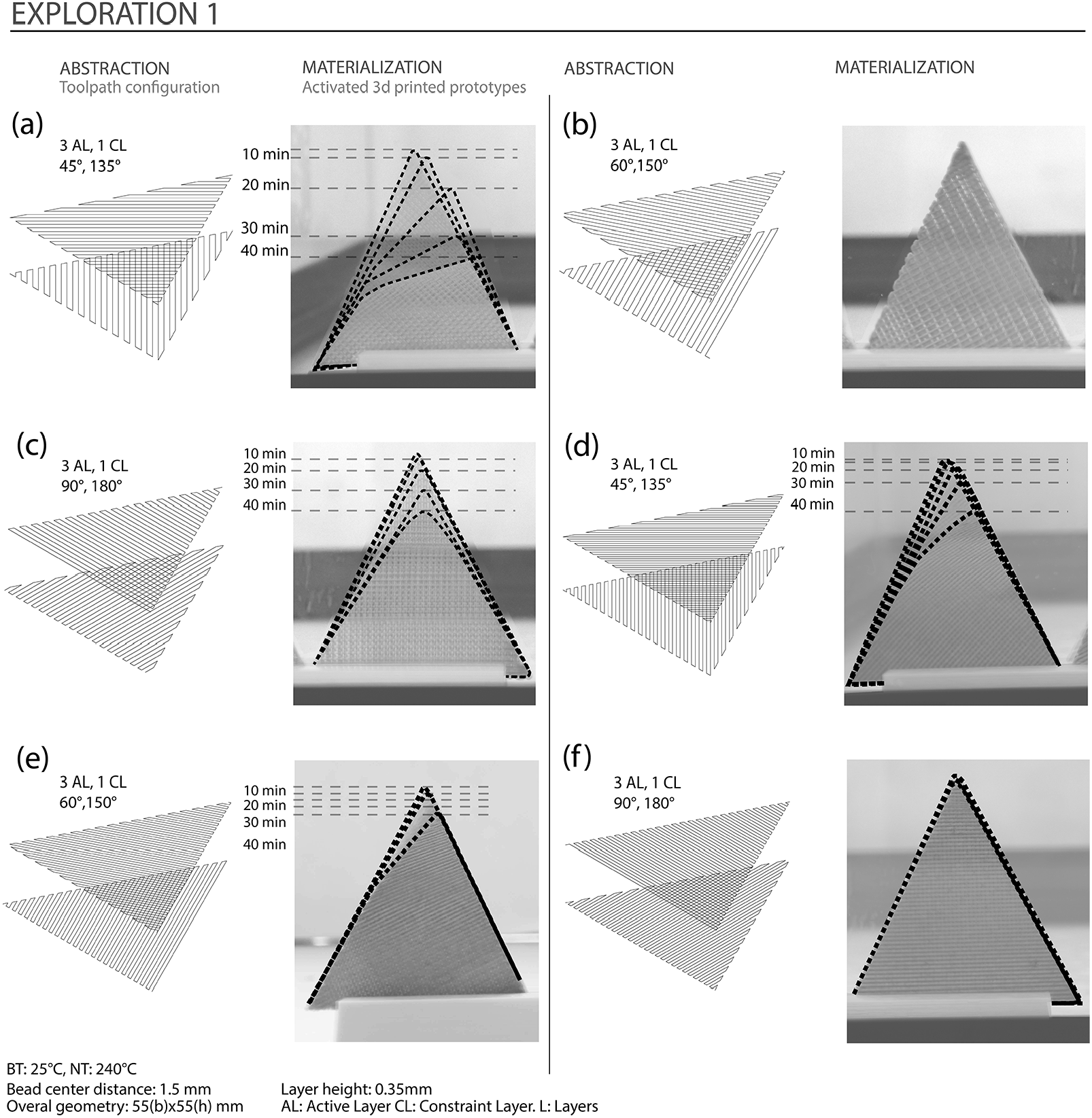
Abstract representations and 3D printed shapes responding to humidity. Prototypes with different printing angle, at a) 45° and 135°, b) 60° and 150°, c) 90° and 180°, d) 45° and 135°, e) 60° and 150° and f) 90 and 180°.
Rules for shape-change: formalizing material transformations
With the aim to formalize shape-change, transformations observed in 3D printed shapes are represented as rules. We make use of image analysis to abstract the changes in the boundaries of 3D printed shapes. The rules for shape-change integrate material transformations of 3D printed shapes into shape computation. As can be seen in Figure 6, the left-hand side of the rules consist in tool path patterns of 3D printed shapes, and the right-hand side represent the boundaries of the activated 3D printed shapes. Therefore, this second set of rules depict material behavior in response to actuation parameters and make explicit how certain variables condition shape-change. Rules S1 and S2 depict the effect of the location of the constraint layer (CL) on the bending response of the resulting surface—whether it would be concave or convex. Rule S3 shows how the direction of the 3D printing pattern of the active layer (AC) conditions the bending response of the 3D printed shapes, by determining the main direction of expansion. Finally, Rule S4 illustrates the relationship between bead center distance and bending response. In a set period, a 3D printed shape with a larger bead center distance would bend more than a 3D printed shape with a smaller bead center distance. These rules guide the tool path design of more complex 3D printed shapes in the subsequent stages of the case study.

Shape-changing rules.
Kirigami rules for amplifying shape-change
The main goal of this second cycle of abstraction–materialization–abstraction is to explore the effects of kirigami geometries on amplifying shape-change of 3D printed shapes. Rules for tool path definition (Figure 4) and rules for shape-change (Figure 6) guide the development of this second set of explorations with 3D printed shapes. A new set of visual rules—kirigami rules—that guide how visual shapes can be divided into parts to acquire different behaviors, are introduced at this stage (Figure 7). The rules follow the synthetic logic depicted in the dukta study by Gürsoy and Özkar. 26 Rule K1 defines the main cut lines on a given shape. The length of these lines (c) and the vertical and horizontal offset distance between the lines (a, b) can be defined parametrically. The cut lines can also have a certain angle with reference to the main geometry. Rule K2 replaces cut lines with rectangles of which the height (d) defines the height of the hinges. Location of the hinges guide the separation of the main shape into different parts, which when materialized as 3D printed shapes can have different properties within the system. They can define bending directions or materials used in 3D printing. Rule K3 identifies and labels these different parts by assigning two alternating colors. Finally, Rule K4 depicts how the rules for tool path definition are applied following the labels, also taking into consideration the rules for shape-change. For instance, Rule S4 can be used to differentiate the parts of 3D printed shapes where there is a need for more bending behavior. The derivation shown in Figure 7 demonstrates the implementation of kirigami rules to design the 3D printing tool paths of a concentric kirigami 3D printed shape. Both linear and concentric 3D printing tool paths are generated for testing in this second stage and 3D printed using hydro-responsive wood filaments.
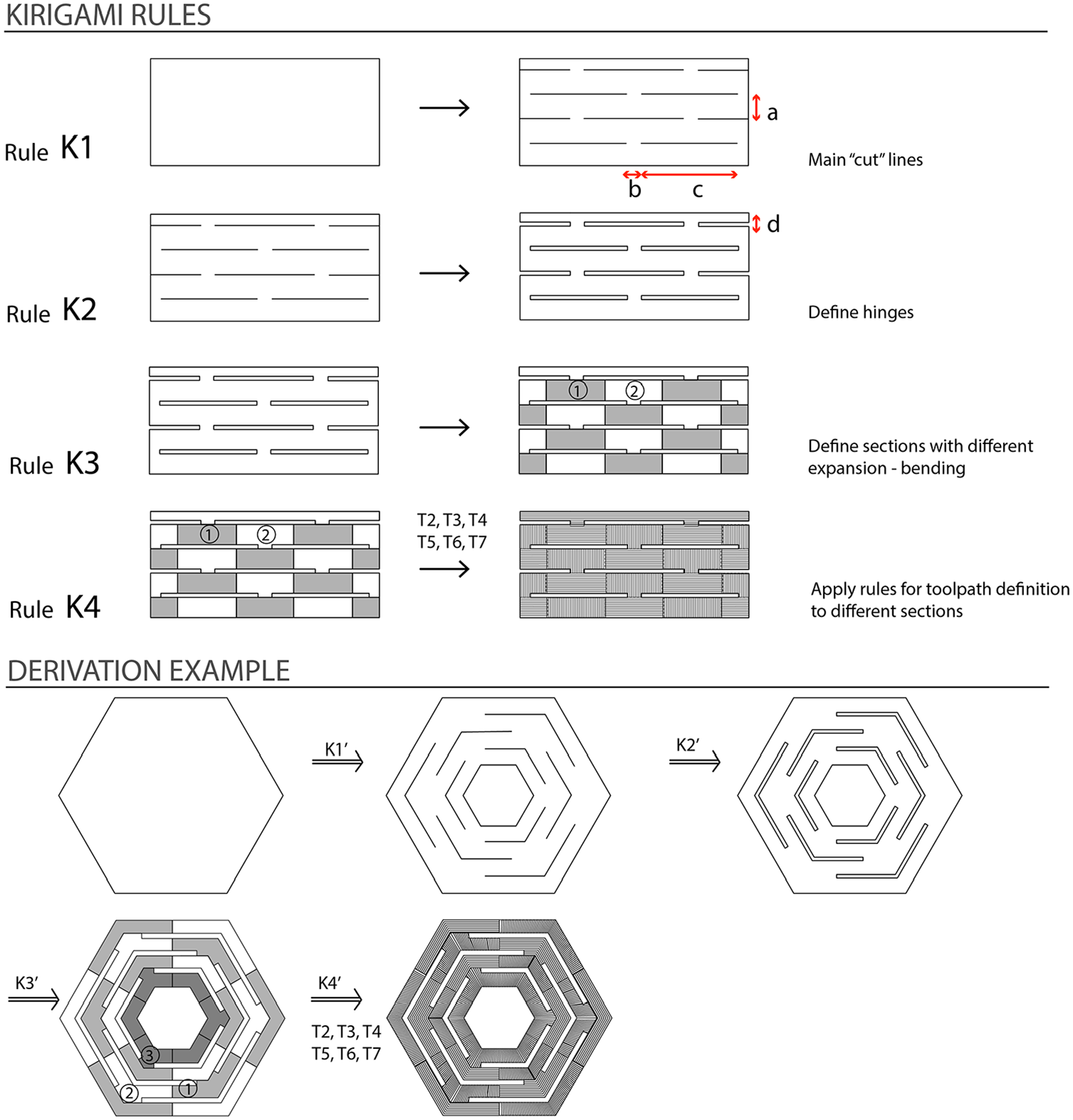
Kirigami rules.
From visual shapes to kirigami 3D printed shapes
In the second set of explorations, we used 3D printing settings and materials similar to the first set of explorations. In this stage, we explored which tool path configurations for kirigami geometries can be considered more successful in amplifying shape-change. A responsive system that displays an amplified shape-change is one that presents a larger overall shape transformation than the sum of its discrete parts. This is particularly significant in the design of shape-changing systems where the strain deformation of smart materials is very small when activated and needs to be amplified. This amplification of shape-change response would also help in scaling-up the prototypes to an architectural scale.
Figure 8 summarizes the findings of this second set of explorations. Left and middle columns illustrate the tool path configurations, and right column shows the humidity-activated 3D printed shapes. As previously presented, three different set of rules were used in the design and fabrication of these 3D printed shapes: rules for tool path generation, rules for shape-change, and kirigami rules. Rules for shape-change guided the bending response of different parts, labeled as 1 and 2. Rules S2 and S3 were alternately applied to these parts to embed concave and convex bending responses to the 3D printed shapes. Several shapes have been 3D printed which have different parts for concave and convex bending response. Kirigami rules have also been used to create variations in 3D printed shapes. For instance, Shapes A and B demonstrate a variation in Rule K2 that defines the height of the hinges. The results of this second set of explorations indicate the feasibility of using kirigami geometries to amplify shape-changing response. Figure 9 shows close up images of the activated 3D printed shapes. Shape A changes from an almost completely closed state to an open state, Shape C incorporates a multi-material approach with responsive and non-responsive materials, and Shape D is a concentric geometry that presents an amplified spatial transformation.

Abstract representations and kirigami 3D printed shapes responding to humidity: (a) Kirigami curvatures, (b) extending hinges, (c) kirigami multi-material, and (d) concentric kirigami geometries.

Close up views of activated kirigami 3D printed shapes: (a) Kirigami curvatures, (b) kirigami multi-material, and (c) concentric kirigami geometries.
Capturing material transformations of Kirigami 3D printed shapes
The last abstraction cycle of the study involves a preliminary attempt to characterize shape-change using 3D scanning technologies. Figure 10 shows the results of 3D scanning 3D printed shape A at intervals of 40 min. The goal of 3D scanning the prototypes over time is to capture the complex transformation mechanism of the hydro-responsive 3D printed shapes. Image analysis process exemplified in the previous stage is not appropriate anymore because of the complexity of the transformation mechanism that the kirigami geometries present. In the following stages of this study, 3D scanning will inform how we can characterize the strain of the material in relation to time. As part of the presented study, little attention has been given to precisely measure the shape-changing response in relation to time. However, we recognize the need to accurately model the behavior of 3D printed shapes before proceeding to a new materialization stage. Further studies will undertake the development of an accurate model that simulates material behavior over time.

Three-dimensional scans of prototype A.
Discussion and conclusion
The research presented in this article runs through discrete but causally interrelated abstraction and materialization phases. As shown in a similar study on dukta transformations, 26 the first phase consists in visual computations to generate 3D printing tool paths. We formalized the generation of 3D printing tool paths through visual rules. The effects of these abstract visual rules on material transformation were unpredictable as they were created either with insight or without considering materiality. When these abstract tool paths were materialized through 3D printing and the resulting wood-based composite samples were exposed to humidity, their shapes changed: New material shapes emerged through spatial displacements of the parts resulting in three-dimensional form configurations. These emergent material shapes are abstracted yet again as visual representations in different formats to continue design exploration.
The framework for research that we developed in this study, starting with a bottom-up material exploration, can potentially be applied to other material explorations with different shape-changing materials. The case study presented in this article, where wood-based hydro-responsive prototypes are 3D printed, illustrates the implementation of this approach in two consecutive stages and contributes to the body of research on the incorporation of responsive wood in architecture developed over the past decade.
Three types of rules are defined in this article. The first type of rules—fabrication rules—include rules for toolpath generation that serve to design the geometric configurations of hydro-responsive systems using 3D printing. The second type of rules—shape-changing rules—integrates material transformation into shape computation. Time is added in the definition of the rule, with a representation of a before and after activation state. The rules for shape-change present a novel implementation of the shape grammar formalism, depicting algorithms that describe the transformation of shape-changing materials. The third type of rules—kirigami rules—serve to design kirigami geometries and apply tool path definition rules to such geometries to amplify shape-change. Rules defined in different stages of the study serve not only to guide the development of the explorations in subsequent stages but also to provide a means for reporting generalizable results. The abstraction–materialization cycles allow us to understand the dynamic behavior of 3D printed wood to be able to design shape-changing architectural systems in subsequent studies. Some architectural applications of hydro-responsive materials can include responsive building skins and self-assembly systems. In our study, actuation parameters remained constant. However, when a particular application is explored, the actuation parameters (humidity, temperature, time) can become the main variables of the bottom-up exploration.
Finally, as designers, we are interested not in defining a specific parameter with scientific precision, but rather, in constructing a model that deals with multiple variables at the same time. In proposing the abstraction–materialization framework, we argue for an approach that abstracts certain aspects of material behavior—the ones that we choose to work with at a given point in time—and compute with those in the development of shape-changing systems. Additional visual and tactile properties can emerge from material manipulations and can further be formalized with new set of rules, making way for different ways to work with shape-change.
Footnotes
Declaration of conflicting interests
The author(s) declared no potential conflicts of interest with respect to the research, authorship, and/or publication of this article.
Funding
The author(s) disclosed receipt of the following financial support for the research, authorship, and/or publication of this article: This research was partially supported by the SCDC Interdisciplinary Research Grant 2018-2019, from the Stuckeman Center for Design Computing, and by the H. Campbell and Eleanor R. Stuckeman Fund for Collaborative Design Research, from the Stuckeman School of Architecture and Landscape Architecture.
