
Abstract
Robotic 3D printing applications are rapidly growing in architecture, where they enable the introduction of new materials and bespoke geometries. However, current approaches remain limited to printing on top of a flat build bed. This limits robotic 3D printing’s impact as a sustainable technology: opportunities to customize or enhance existing elements, or to utilize complex material behaviour are missed. This paper addresses the potentials of conformal 3D printing and presents a novel and robust workflow for printing onto unknown and arbitrarily shaped 3D substrates. The workflow combines dual-resolution Robotic Scanning, Neural Network prediction and printing of PETG plastic. This integrated approach offers the advantage of responding directly to unknown geometries through automated performance design customization. This paper firstly contextualizes the work within the current state of the art of conformal printing. We then describe our methodology and the design experiment we have used to test it. We lastly describe the key findings, potentials and limitations of the work, as well as the next steps in this research.
Introduction
This paper explores the potentials of conformal printing within architectural fabrication. We present an approach that connects conformal printing to the real-time registration of unknown geometries via 3D scanning, and to the automated generation of printing geometries that respond to the performative capacity of the registered geometry. This integrated approach offers the advantage of responding directly to unknown geometries through automated design customization, and opens up several possible novel architectural applications. In this paper, we firstly describe current applications of additive manufacture in architecture, and identify key limitations which could be overcome by the use of conformal printing. We outline three scenarios whereby conformal printing can support greater sustainability within architectural fabrication. We contextualize our approach through analysis of relevant research in conformal printing and approaches taken to registration and adaptive response. We then describe the technical aspects of our methodology and demonstrate and evaluate the feasibility of the developed workflow in a proof of concept study of one of these scenarios, and detail the results. We lastly discuss the key implications, contributions and limits of our approach.
Additive manufacturing for architectural sustainability
Additive manufacture (AM) technologies, considered one of the pillars of Industry 4.0, 1 use the precise layered deposition of material to fabricate 3D objects from a digital file quickly and cost-effectively. They are currently applied to the printing of component parts, 2 building elements and small-scale buildings. 3 They are also becoming a key means to address challenges of sustainability: by enabling the customization of complex tailored geometries, 4 the optimization of material quantities, 5 the introduction of new sustainable materials, 6 and through the reduction of transport, storage and supply-chain costs.
Despite the rapid development of various AM methods, in particular the introduction of robotics, the conventional approach of 3D printing an entirely new and complete part by depositing a material on a flat substrate using planar and parallel layers remains the same. While significant recent research efforts have focussed on the adaptation of printing heads to a myriad of different materials, 7 and there has been a rapid growth and development of 3D scanning technologies, including portable RGBD cameras and structured light scanners, 8 the underlying principles of 3D printing, that is, motion control systems (gantry, delta or robot arm) and assumptions about the substrate have not received the same attention.
While appropriate for many applications, this limitation causes the AM process to miss opportunities for further sustainability, including the addition of new functionalities to existing surfaces, hybridizing fabrication processes, extending generic parts through optimized customization, working in conditions of uncertainty or partial knowledge, and bridging between precise fabrication processes and unpredictable sites or material behaviours.
Challenging the assumption of a planar substrate
New research has introduced the concept of conformal printing – the idea of 3D printing onto existing 3D objects with non-planar or uneven 3D surface geometries. In contrast to the conventional approach of 3D printing even horizontal layers onto a flat plane of known position, conformal printing requires an explicitly defined surface representation, defined as, either a numerical or geometric model, or gained via sensor feedback. In this research we explore the latter approach and develop a workflow that enables conformal 3D printing onto existing objects with unknown surface geometries. This is achieved through a two step robotic 3D scanning process that registers and digitizes the unknown surface geometry as a point cloud representation. This point cloud is further transformed into a mesh upon which tool paths, defined via an integrated neural-network based design process, are generated to enable printing onto that object’s surface. The accuracy of the scanning process is critical to enable the tolerances required for 3D printing.
Challenging a mono-material paradigm
Whether on or off-site, the current paradigm of architectural AM is focused upon concrete, and the printing of mono-material buildings or elements. State of the art built examples such as those made by the Winsun company have used a large extrusion-based 3D printer to build houses, offices and a five story apartment building. 9 All the components necessary for these buildings are printed separately off-site before transporting and assembling them on site. The Huashang Tengda company has 3D printed a two story villa as a single print, using on-site printing. 10 In these projects, the perceived benefits of AM include reductions in construction waste by eliminating formwork, optimization of construction time and cost, and reduction in the potential for injury. However, by restricting the fabrication process to a single fabrication method not only the material complexity of architecture becomes limited to a single substance but also opportunities to include more effective and time efficient fabrication approaches achievable via traditional machining are missed.
An alternative is to combine different manufacturing processes (additive with subtractive or formative) within a single workflow. This is termed a hybrid manufacturing workflow. The purpose of developing a hybrid manufacturing workflow is to enhance the total advantages of a fabrication process whilst at the same time minimizing the specific disadvantages of any single component of that process. 11 To give this concept architectural implication, we consider this term more broadly than simply coupling additive and subtractive processes into a single workstation, or a single machining process. 12 By allowing fabrication operations to be displaced in time and space, this concept offers a productive path for architecture to extend the base idea of conformal printing in novel ways. We propose three immediate applications in renovation, in adapting generic building elements to specific circumstances, and in multi-material printing:
Renovation scenario. Renovating buildings is an extremely cost efficient way to address the challenges of climate change, and an area where the potential energy savings are among the largest. Currently, renovation and reconstruction is estimated to account for the large majority of building work in Europe. In fact, 40% of residential building stock dates from before 1960, and 60% of non-residential building stock is built pre-1980. 13 Renovation is key to building adaptation, in order to deliver sustainability and meet mandated improvements in energy efficiency such as Directive 2010/31/EU. Built projects such as Quay Quarter in Sydney demonstrate the increasing scale at which renovation strategies are being deployed, in this case applying new cladding onto an old highrise. In a renovation scenario, AM could be used to print new elements onto existing building structures, which would function as the substrate. The hybrid manufacturing workflow would thus stretch between prior construction of varying materialities and new construction via AM.
New build scenario. A second scenario focuses on new buildings. Here, prefabricated architectural elements such as facade units are built off site to a high precision, while the building substructure is built on-site to a lower precision. The challenge of negotiating this discrepancy is well described in Brandt. 14 As the discrepancies are often discovered on-site, the adaptation needs to occur on-site as well, for example, adapting to the tolerances of an erected structure. A hybrid manufacturing workflow would print locally responsive performance specific geometries onto the generic prefabricated elements, using them as a substrate.
Emerging materials scenario. A third example is printing with volatile materials. With the emerging shift to bio-centred digital fabrication comes a greater need to integrate material behaviour because, while bio-materials can be abundant and inexpensive,15,16 these emerging materials are also very challenging to work with. 17 This is because they are less understood, are often highly heterogeneous both within a material and across batches, and are significantly affected by warping, shrinkage and other process-induced deformations. In this scenario, the hybrid manufacturing workflow involves printing with a single or multiple materials in stages, and using the first stage of printing as the substrate for the second.
As we detail in the following section, 3D scanning is a critical enabler for the conformal printing process in each of these architecturally relevant scenarios.
State of the art
Approaches that assume an a-priori geometric definition
Conformal printing on 3D substrates in contemporary research explores different substrate registration techniques and additive material deposition techniques. An immediate research focus has been the quality of the print and its adherence to the substrate. To limit complexity, researchers print upon standard geometric shapes such as oblique planes or cylinders and spheres. In this case a simple geometric or numerical model is sufficient to project the toolpath to the substrate surface. This approach applies to different materials, that of desktop thermopolymer 3D printers, 18 static clay extruder printing onto a robot arm holding a cylinder, 19 as well as large scale robotic concrete printing on metal reinforcement meshes. 20
Approaches that do not assume an a-priori geometric definition
This research strand instead places focus on the geometric complexity of the substrate. The substrate in this case is unique to the specific print. For instance, generic low-tolerance substrates can be made of granules such as sand or gravel. These can be reused for multiple prints, and they present no need for registration. Excess material is mechanically shaped away using a carving end-effector, before the concrete printing can start. Laser scanning can be used to subsequently verify that the printed geometry conforms to the design intent. 21
In cases of two-stage hybrid fabrication processes, where the substrate is robotically manufactured from stock material, the printing process can directly utilize the digital representation of the fabricated piece, thus relying on the high precision of the robot. 22 While this can apply to subtractive fabrication such as hot wire cutting, it is not sufficient for processes where material behaviour during fabrication affects the final results. This is the case with thermopolymer 3D printing for instance, where the cooling of the material causes it to shrink and warp, thereby affecting the precision of the conformal printing. Here sensor feedback is needed to adapt a digitally pre-computed toolpath to the physical geometry of the substrate. Laser beam probing can be used to generate a measuring map, and compute a one-time vertical repositioning of the print targets to a correct height to achieve good adhesion of printed CFRP tension reinforcements. However, the measuring process has been reported as very lengthy in time, taking as much time as the printing itself. 23 Conversely, on-the-fly toolpath adaptation allows for measuring and printing to occur concurrently. It requires an advanced robotic setup constantly querying an ‘eye-in-hand’ or ‘birds-eye’ live sensor feedback and integrating the data into the printing process. This has been applied to printing on pneumatic membranes, where a load cell detected deflections of the inflated membrane, and calibrated the robot’s pressing of the carbon fibers. 24
Approaches that are reactive to the substrate geometry
In the previous examples, the sensor feedback only serves to adapt digitally defined targets to the real physical geometry of the substrate, but all design or geometric intent of the toolpaths is pre-defined and pre-computed. However, the geometry of the substrate presents an architectural opportunity for generative design of the printed pattern. This can either be a pragmatic toolpath design, for instance a space filling polyline to ensure the entire substrate is covered with print material. In this case, 25 a tensioned carbon fibre mesh is scanned using a Kinect RGBD scanner and a robotic toolpath for concrete spraying is generated according to the bounds of the geometry. It can also be an artistic toolpath design, such as using the topography of artistically shaped substrate as a driver for the design. In this case 26 the clay substrate shaped by a ceramist was scanned with a FARO lidar scanner and filigree clay lines were robotically printed.
This project belongs to the third group of examples, as conformal printing happens on a digitally- unknown panel substrate. However, it goes beyond state of the art in two aspects: Firstly, it is not the geometry of the substrate that informs the toolpath generation, but rather an analysis of its performance under certain conditions. Secondly, the project develops an integrated digital pipeline where all processes are directly triggered from within Grasshopper visual programming plugin for Rhino, which is a common design modelling software for most architects and designers. This integration allows for the design process to remain undisrupted and guarantees a rapid turnover from 3D scan to 3D print.
Methodology
In order to exemplify one of the many architectural possibilities that can be unfolded using Conformal 3D Printing, in this paper we report a model workflow for the performance customization of architectural panels. We develop 3D printing of structurally informed differentiated patterns onto arbitrarily shaped 3D architectural panels (Figure 1). We describe the digital pipeline that we have established to guarantee undisrupted flow of data between the different steps of the conformal printing process. The workflow, is composed of a series of concatenated processes: Registration of the unknown substrate geometry using a dual-scanning process, processing of the scan information and encoding them as an input of the neural network, predicting the performance of the panel using the neural network, and finally using the prediction to generate the printing toolpath. The technicalities associated with these processes are elaborated in the following subsections.
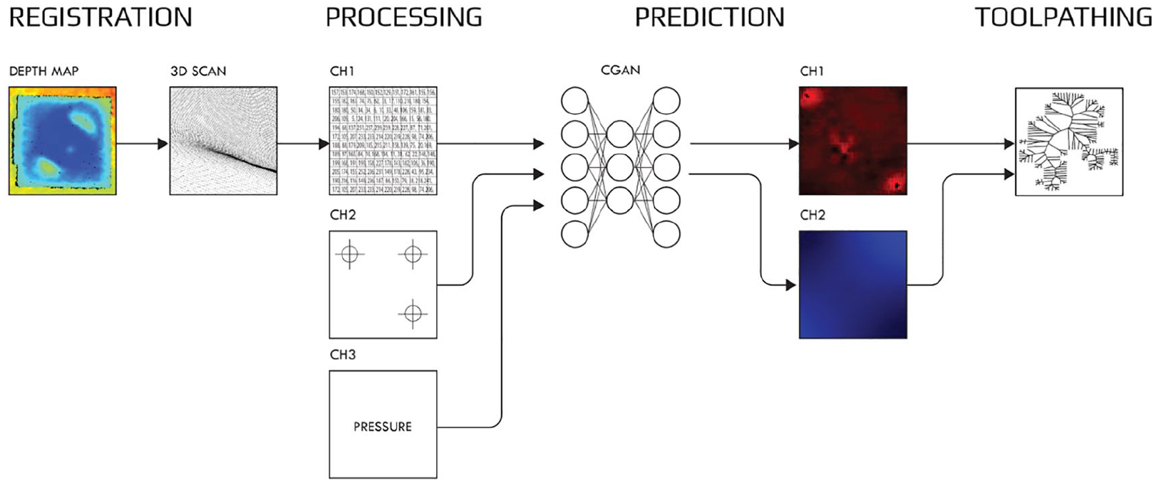
Diagram of the developed 3D scan to 3D print workflow: The point cloud from the dual-scanning process is encoded as an image and fed to the Neural Network in order to predict its structural performance under perpendicular load. The prediction is used to inform the generative reinforcement pattern to be printed. Gcode is then generated and sent to the Robot for execution.
Multi-resolution scanning
The starting point of the established workflow is a two-stepped automated robotic scanning process. In the first step, a low-resolution scan with an Intel RealSense D435 RGBD camera, mounted on a UR10 robot, is used to register the arbitrary panel. Automated clipping based on depth-planes allows the bounds, orientation and varying surface heights of the panel to be identified from the scan area. The scan area is limited by the reach of the robot arm and the camera FOV, which in this case is 87°±3° × 58°±1° × 95°±3°, Once the panel is identified, a parametric algorithm in Grasshopper for Rhino automatically generates the detailed robotic scanning toolpath for the second, high resolution scan. The toolpath first tracks the outline of the element, and then follows an infill path (Figure 2). This second high resolution scan is executed by the same robot, but via a different Artec3D EVA structured light scanner. Both scanners are mounted to the flange of the robot with a bespoke mounting bracket (Figure 3). While this scanner is intended for hand-held usage, the robotic scanning process is used to ensure that a constant optimal distance of 450 mm between the scanner and the object is maintained, while allowing for it to adapt to the orientation of the object. Once scanning is complete, a custom computational procedure in Grasshopper automatically crops and orients the generated high resolution point cloud.

Dual-resolution scanning setup (right) and workflow (left). The low-resolution scan from the RealSense camera (top) is processed and used to generate the robotic scanning toolpath (bottom) for the EVA scanner. The robot first does a perimetral motion, followed by an area filling one.
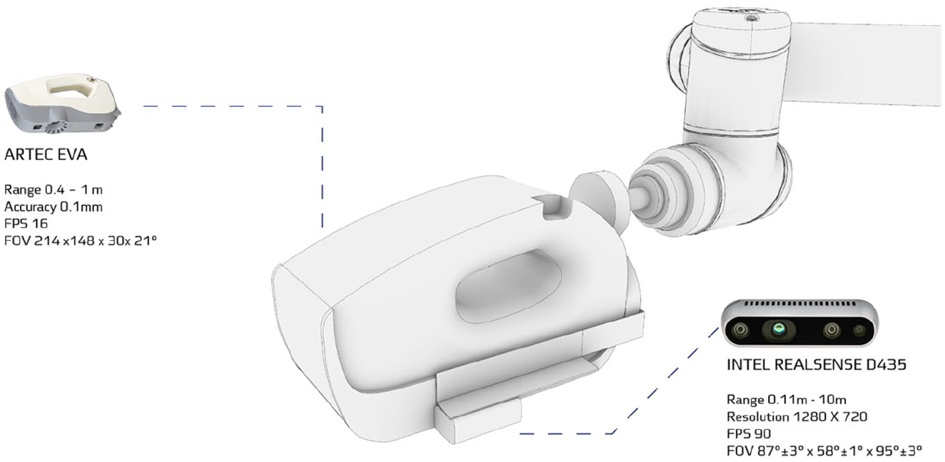
Custom robotic end effector, combining an Artec3D Eva scanner, and a RealSense D435 RGBD camera onto a UR10.
Machine learning: conditional generative adversarial networks
A focus of sustained architectural research, 27 Machine Learning (ML) applications are currently growing within five practices 28 : ML for analysis, optimization and search of design, ML for short-circuiting simulation, ML for dataset classification, ML for adaptive operation and finally ML for fabrication data, the practice this research addresses. Fabrication applications are often complex problems requiring spatial correlations, such as mapping and grading performance, 29 or controlling geometric deformation. 30 To use this spatial information as training data, they require custom representational approaches that translate geometric features into images that can be analyzed by a Neural Network. In this project we use a similar representational approach 31 of false colour image generation to train a Conditional Generative Adversarial Network 32 (cGAN). However, our approach is different to previously reported approaches 31 in that the images are encoding a digital generatively generated dataset, rather than encoding physical prototypes.
Once registered by the scanner as described in Multi-resolution Scanning, the performance of panel geometries under wind load are predicted. The prediction requires panel geometry information combined with user specification of support points. A wind loading of 1500 Pa perpendicular to the panel plane is assumed. The usage of an in-house trained cGAN allows for a quick analysis of this structural performance without having to manually program a Finite Element Analysis for each panel. In this way, predictive structural information can be gained directly from an unstructured point cloud in an automated way. This quickly becomes crucial when dealing with design exploration and high-volume batches of panels during design scenarios. In our integrated workflow, the oriented high resolution point cloud generated in the previous process is analyzed using a custom computational procedure in the design software Rhino & Grasshopper. The features of the panel are extrapolated and encoded as a false-colour image. By inputting this encoded representation of the geometry of the panels and designed structural supports, the network is able to return a von Mises stress mapping as well as a Normal Displacement mapping of the panel under wind load (Figure 4). The prediction is triggered directly from within the Grasshopper modelling environment and is run in the back-end using the Python programming language and TensorFlow.
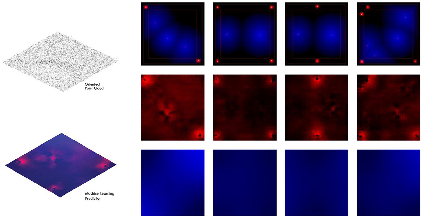
The workflow connects an unstructured scanned point cloud to a Neural Network-based prediction of stress and deflection, all parsed within the Grasshopper environment (left). Image encoding geometry and support point information that is input to the cGAN (right), von Mises stress map (middle) and normal displacement maps predicted by the Network (bottom).
Generative reinforcement pattern design
The Neural Network encodes its structural analysis prediction in the form of a false colour image. This prediction is directly read back into the Grasshopper modelling environment. A custom computational procedure constructs a vector field which serves as input for the generative reinforcement pattern. The design possibilities are endless. In the context of this paper we have explored four different families of patterns. For instance, one is a recursive subdivision pattern where the number of iterations is informed by the stress state of the cell. Another pattern uses recursive branching also informed by the stress state. The third creates a re-parameterized mesh based on the stress readings. The fourth pattern creates a false-mesh whose topography is based on stress readings and is then used to draw flow lines from its peaks to valleys on a stress map (Figure 5). All of these generate the printed reinforcement material distribution over the panel surface. They are then augmented in height based on layering logics. The structural supports of the panel are designed as an integrated part of the print.
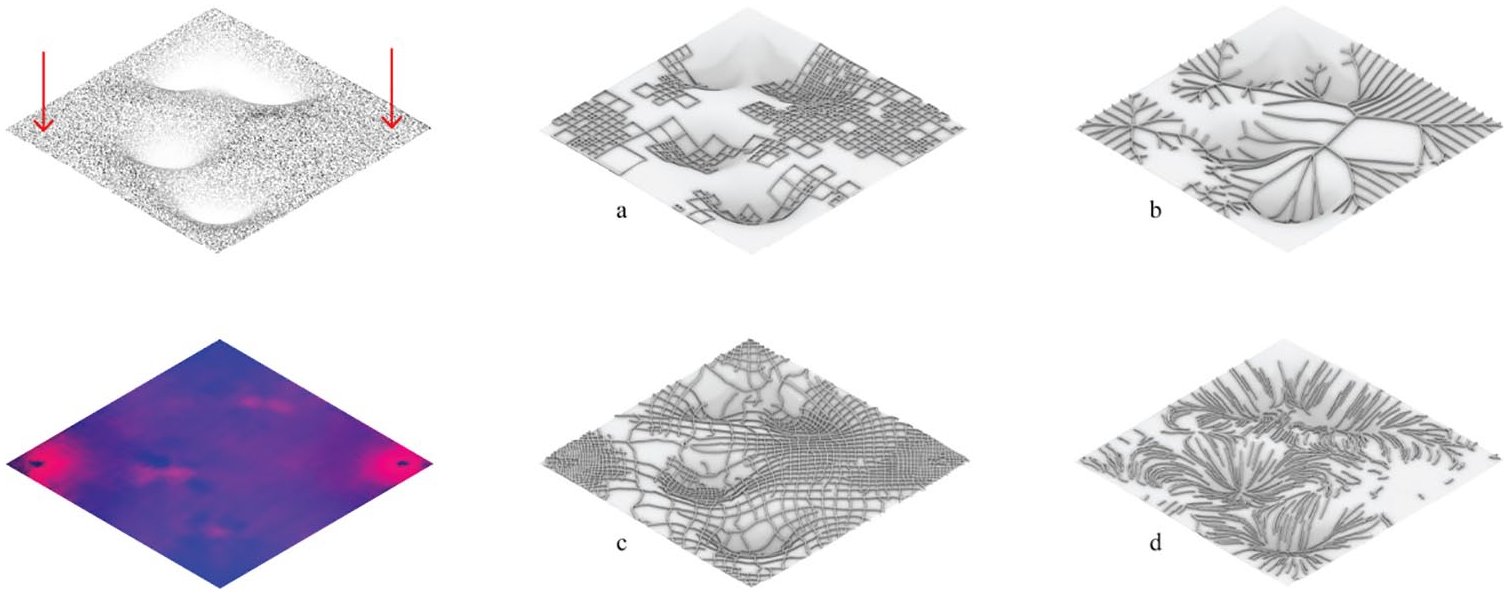
The four families of generative reinforcement patterns reacting to stress case on a given panel. Specific panel geometry( Top left); and stress map (bottom left); four different families of reinforcing reacting to stress case (right). (a) Octree recursive subdivision pattern; (b) recursive branching pattern; (c) reparameterized mesh pattern; (d) flow lines pattern.
Conformal 3D printing robotic setup
The setup comprises two UR10 robots, that are working in collaboration over a geometrically unknown panel (Figure 6). One robot is fitted with the scanning hardware. The second robot executes the printing of the generated reinforcement pattern. It is fitted with a custom built pellet extruder. The extruder uses a step motor to control an auger screw that drives the pellets into the heat chamber. The material flow rate and heat temperature were controlled by a proportional integral derivative (PID) controller. A custom algorithm developed in Rhino/Grasshopper translates toolpath designs into Gcode files. The point coordinates and associated orientation vectors are then sent to the robot using RoboDK, which computes an optimal toolpath trajectory through inverse-kinematics, and overcomes the 2000 line limit when sending files from RobotsIO in Grasshopper.
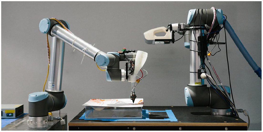
Two UR10 robots working collaboratively in a shared workspace. Scanner Robot retreats after scanning, giving way for Printer Robot (Right) to execute the material deposition (Left).
Design experiment
In order to demonstrate and evaluate the feasibility of the developed methods and workflow we undertook a proof of concept study in form of a design experiment. Our experiment tests the ability to adapt facade panels to be specifically tailored to their position along the facade, in terms of perforation, rigidization, shape, and holding supports, thanks to conformal 3D printing. Here we focus on rigidization. The design task was to fabricate a series of conformally printed facade panels. We set ourselves to create unknown panel geometries. We milled 20 different wooden substrates that we used to design the distribution of topography on the panel surface. They were primed to guarantee smoothness. We subsequently fabricated the panels by thermal vacuum forming 2 mm thick clear PETG sheets over designed distributions of the wooden substrates (Figure 7). The panel dimensions were 430 × 430 mm due to the size of the vacuum forming bed. Although one could digitally model the distribution of the wooden substrates over the sheets, that digital representation could only be a low-fidelity translation of the real panel, due to the thermal behaviour of the sheet during the forming process, which would cause shrinkage and warpage. High-quality conformal printing necessitates a precise geometric representation to ensure the adherence of the printed layer to the substrates. The thermoformed panels were scanned and processed using the methodology described earlier. Support points are defined via user interaction, and constrained to fit within an offset of the panel boundary. The encoded information was input to the Neural Network, and the resulting stress predictions were used to generate the distribution, application, and density of reinforcement patterns (Figures 5 and 8). These reinforcement patterns were then printed onto the panels.
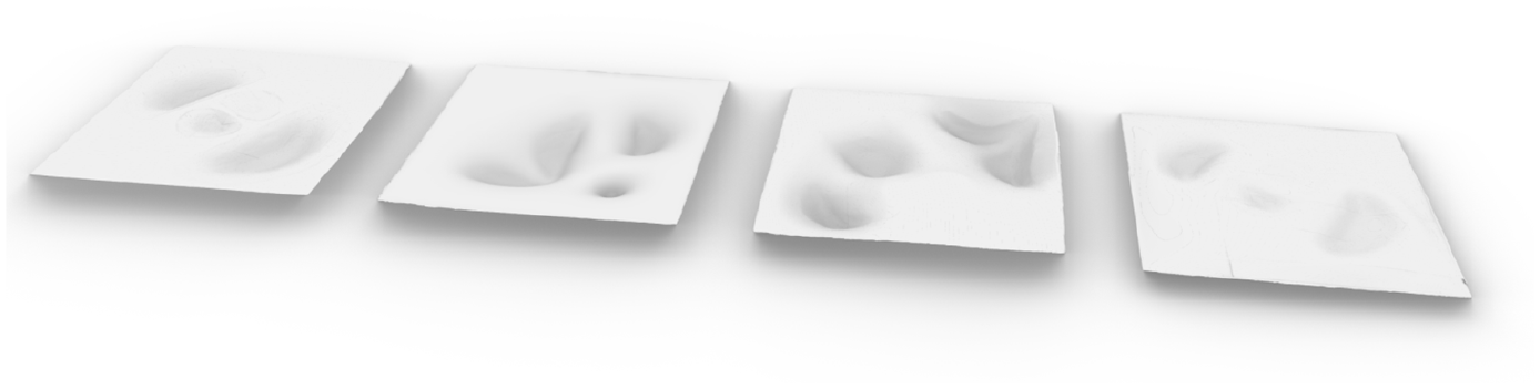
Digital mesh reconstructed from the 3D scan of the vacuum formed panels, serving as substrate for the conformal printing. The panels are varied in the steepness and distribution of their topography, to test the predictive capacity of the Neural Network.
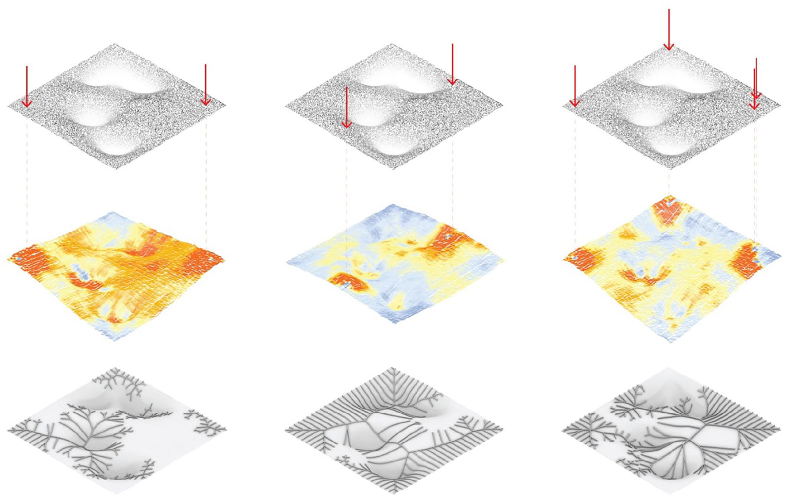
Pattern generation. Point cloud of one 3D scanned vacuum formed panel with varying support points indicated in red (Top row), predicted deformation and stress state based on Neural Network prediction (middle row), resulting recursive branching pattern reinforcement pattern reacting to the Neural Network input (bottom).
Results
The conducted experiments show the high level of integration possible and opportunities afforded by the developed workflow. While maintaining grasshopper as the main user design interfaces, data can flow in the backend between different softwares, from 3D scanning to 3D printing. The experiments also showed interesting results on the specific processes composing the workflows.
Scanning and registration
The workflows have proven the efficacy of mounting a scanner to the robot. An ‘Eye-in-hand’ RealSense RGBD camera allows users to obtain a very quick overview of the robot’s surroundings. The ease of programming this camera using Python makes it an appropriate tool for further applications of robots responding to their surrounding production environments, allowing them to iteratively determine further actions based on the scan. This could include detailed secondary scanning path-planning as we have explored in this case, or for obstacle avoidance workflows in other cases. The robot also allows users to make the most out of the Artec3D Eva scanner, compared to using it as a handheld tool. In fact, by tuning the toolpath parameters, we are able to scan in a very quick and stable manner, reaching speeds as fast as 70 cm/second at 10 fps, without the scan losing quality (Figure 9). This is by far exceeding any performance a user could have holding the scanner by hand.
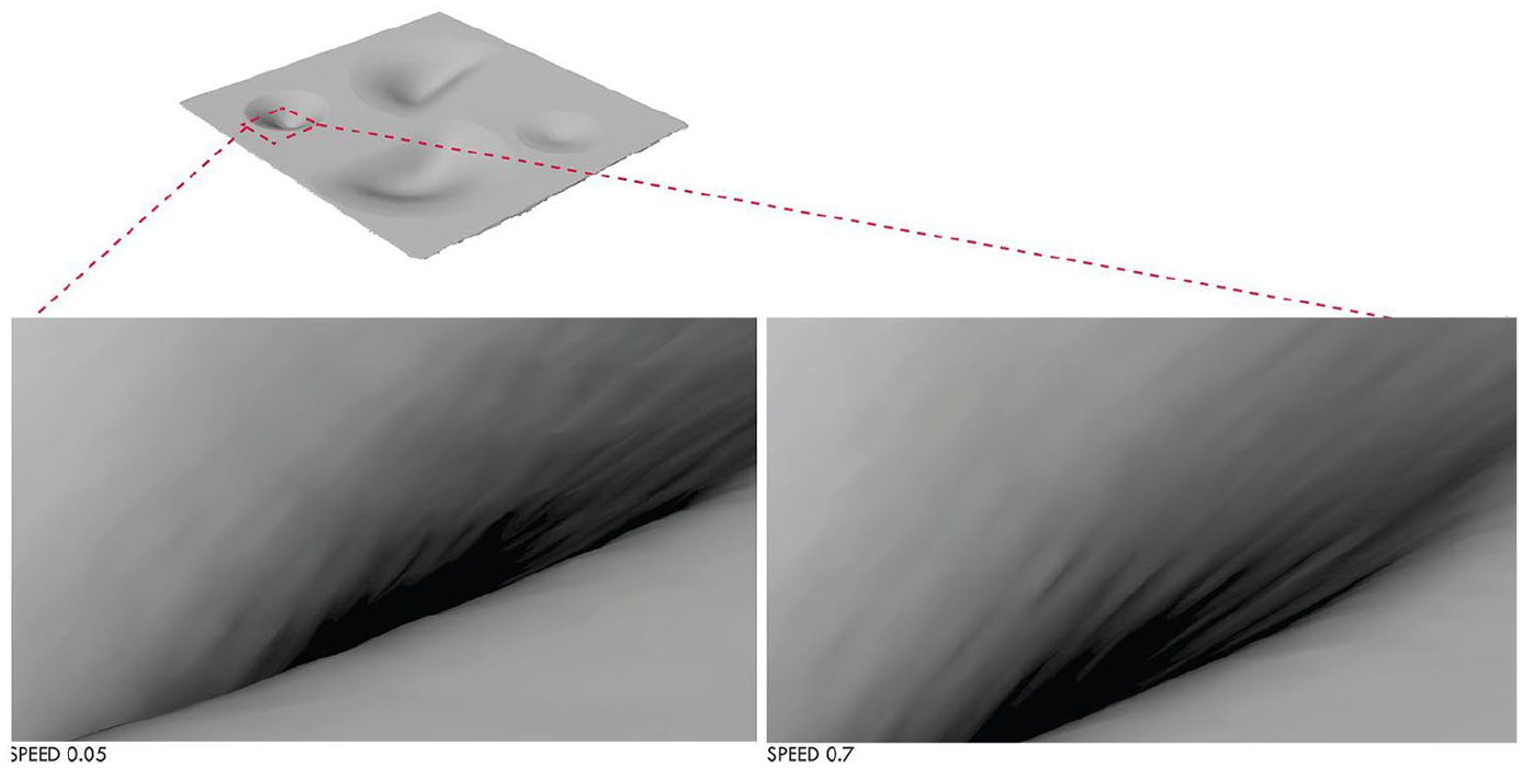
Various scans at various speeds were conducted to find the most efficient scanning inputs to generate the quickest scan without compromising the quality of the scan. Testing at 0.05 m/s, 0.1 m/s, 0.3 m/s, 0.5 m/s, 0.7 m/s and 0.9 m/s. The Scan at 0.7 m/s was found to be the most optimal. Generating smoother point clouds without causing vibrations from the robot, and produce a scan that captures the detail required for machine learning and 3D printing.).
Performance prediction using neural networks
The workflow expands upon the current state of the art, and proves the ability to use an entirely digital proxy dataset to train a Neural Network that would predict the behaviour of physically fabricated panels. The speed and ease of input encoding and result parsing within Grasshopper makes the FEA Neural Network for unstructured point cloud work as an immediate design tool for the user. An additional publication focusing on the Machine Learning workflows utilized in this project is currently under review for a specialized journal.
Conformal printing with PETG
Experiments were carried out printing with a novel recyclable material: PETG pellets. The material exhibited stable printing behaviour and good adhesion to the substrate. PETG produces a clear print. Experiments were made to explore its mixing with coloured ABS masterbatch: this allowed for the creation of uniquely coloured prints with gradients of hue and saturation (Figure 10). This can be seen as a placeholder for multi-material printing based on informed performance, in future work.
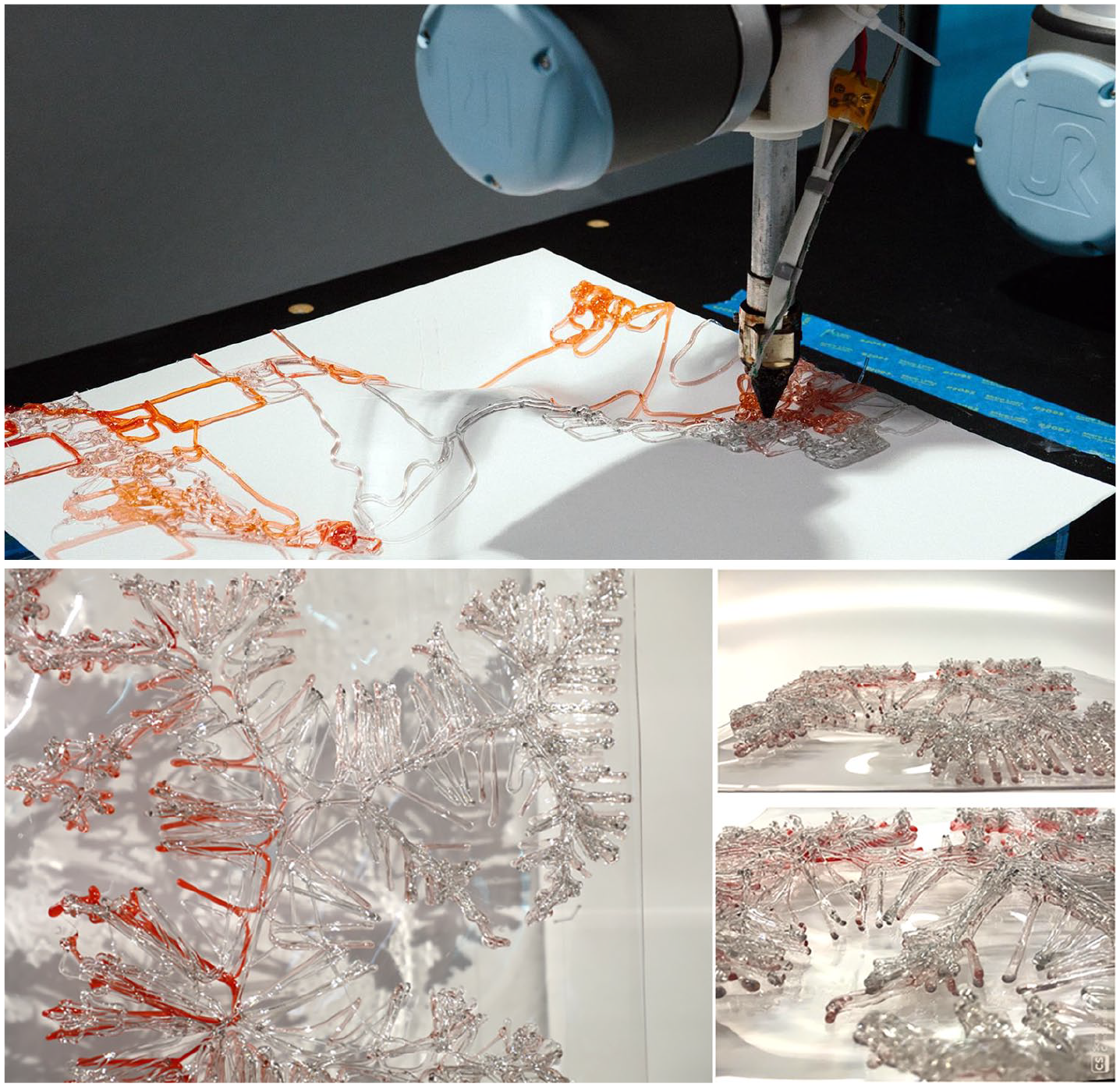
Conformal printing of differentiated pattern on panel (Top) and details of 3D printed panel (bottom).
Discussion and conclusion
In this paper we have demonstrated a novel workflow for conformal 3D printing onto unknown 3D substrates. The workflow advances on state of the art in its two-step eye-in-hand approach to scanning to locate the pose and geometry of the substrate, as well as in the generation of toolpaths on the basis of the predicted performance of the scanned substrate. We show the possibilities of enhancing our modelling environment with external processes without disrupting the data flow. Additionally, we show that robotic scanning offers great possibilities for smart environment-aware iterative robotic fabrication. We also show that Neural-Networks trained on digitally compiled datasets have potential to integrate analytic and predictive information, which typically is time intensive to generate, into real-time design and fabrication processes. Future work will look into maturing the applications of conformal 3D printing with respect to architectural facade systems, and the role this technology could play in bridging between generic mass-produced facade panels. It will include empirical testing of the fabricated panels to establish their performance, and also explore the two yet untested scenarios we discuss in Challenging a mono-material paradigm.
In the broader perspective, this article has argued that architectural conformal printing can open up novel scenarios that can address current issues of sustainable practice, through the inclusion of 3D scanning. Scanning offers the advantage of responding directly to unknown geometries through automated design customisation. The scenarios expand the idea of conformal printing and its extension in hybrid manufacture into new configurations, which we believe will continue to develop, as further research into architecture begins to incorporate conformal printing. Most critically, however, these scenarios make plain the importance of connecting the design process into the registration and printing workflow. The coupled predictive and generative approach we describe here demonstrates that when design is included, response can move beyond simply adapting pre-defined information to a registered geometry, and instead respond to the consideration of its performance implications. This challenges the current approach to fabrication in which a complete set of design information must be explicitly defined in advance, and where adaptation is aimed at reducing tolerance. It invites us to imagine the new modes of design-to-manufacture that will be unlocked as we move further into the Industry 4.0 paradigm, and the imminent profusion of robotics on the construction site.
Footnotes
Acknowledgements
The authors thank Stefan Lie and Teresa Vidal for their valuable insights and support as well as Tran Dang, Gwyn Jones, Tony Jones and Andrew Purnell for their technical support. From Arup we acknowledge David Gerber, Bree Trevana, Alessandro Liuti, Deepika Jaduram, Andrew Weetman, Haico Schepers and Laura Craft. Lastly, Ben Tam from Qubic for generously providing us with the scanner.
Declaration of conflicting interests
The author(s) declared no potential conflicts of interest with respect to the research, authorship, and/or publication of this article.
Funding
The author(s) disclosed receipt of the following financial support for the research, authorship, and/or publication of this article: This research is developed and funded in collaboration with Arup as part of the Global Research Challenge 2019.