
Abstract
This work presents a method for retrieving 3D building contours usable in facade retrofitting projects, which uses a parametric modeling workflow that utilizes a point-cloud slicing method to retrieve such 3D contours. Since current commitments by European governments seek to reduce energy consumption as a means to reduce carbon emissions from building stock by 2050, facade retrofitting appears as an alternative for addressing operational and embedded building emissions. Within such a context, the main contribution of this work consists of a workflow and a 3D reconstruction solution that uses a parametric environment for capturing building topology and bypassing ground-level occlusions. A real case study and a strategy for converting 3D building contours into Industry Foundation Classes entities, directly from the parametric modeling environment, served as a scenario for testing the capabilities of a Grasshopper solution and open new perspectives for this approach.
Keywords
Introduction
As the use of building information modeling (BIM) for the architecture, engineering, construction, and owner-operated (AECO) industry becomes widespread, its full potential is achievable by its implementation throughout the entire lifecycle of buildings. Within such scope, the need for as-built information becomes relevant inasmuch as current commitments by European governments aim to reduce energy consumption as a means to reduce carbon emissions, which, in turn, are expected to help control climate change by decarbonizing the European building stock by 2050. 1 This is mainly because at least 75% of the European building stock is energy inefficient, 2 which reveals the need for adopting retrofitting strategies aimed at accomplishing energy consumption goals that tackle both operational and embodied building emissions. 3
Facade retrofitting appears then as a strategy for reducing operational emissions from two key sources: heating and air conditioning. To attain its goals, facade retrofitting requires accurate information regarding the building’s envelope. As-built information in the form of object modeling has proven to be relevant to the AECO industry in the framework of operations and maintenance (O&M), facilities management (FM), and building retrofitting. 4 In order to provide the AECO industry with reliable information, data acquisition techniques based on point clouds obtained using terrestrial laser scanning provide a starting point for structuring solid building data. 5 As-built 3D models, constructed from point clouds (hereafter PC_Sets), reduce inaccuracies by narrowing interpretation, which is a common problem when working with unstructured 2D as-built documentation. 6
Furthermore, retrieving reliable contours from PC_Sets help develop nesting solutions for facade retrofitting. This is achieved by providing accurate references of levels, locations, footprints, and dimensions for key building envelope components such as walls, slabs, columns, doors, and windows.
The literature cited throughout this article, which spans 7 years, shows that the last 5 years have seen an increasing activity in the study of the referred topics (Figure 1). Many of those studies have addressed the problem of converting point clouds into BIM models by utilizing image treatment and PC_Set segmentation techniques, whereas some others have proposed geometrically based methods to generate as-built contours. However, very few have considered the possibility of using a native modeling environment to do so. Keyword map of recent works dealing with building reconstruction from point clouds.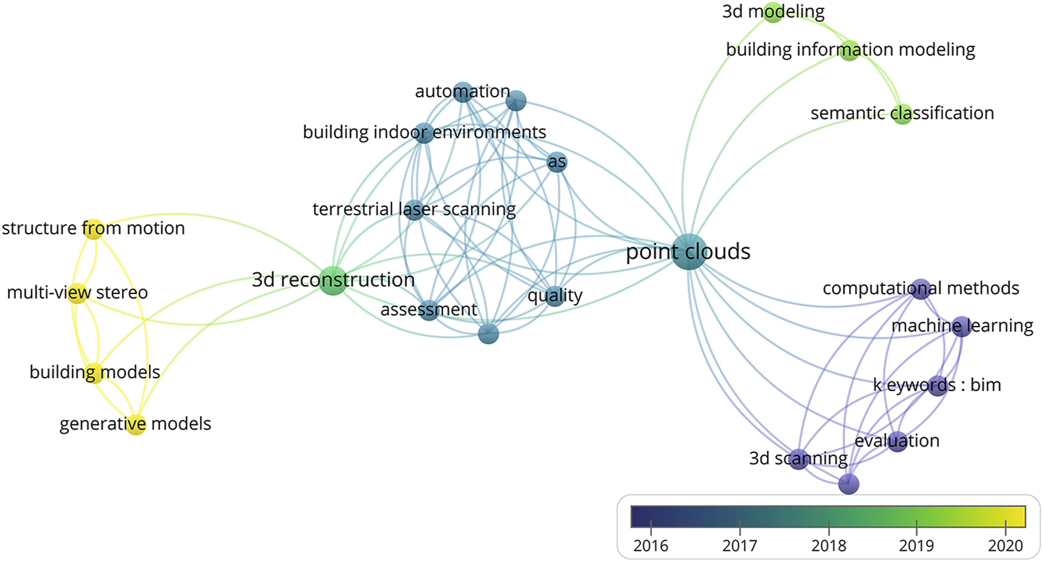
Contributions and structure of the article
This article investigates an alternative for digitally reconstructing building contours for facade retrofitting. It proposes a digital method for as-built contour reconstruction using a native NURBS 1 modeler, as similar endeavors by computing engineers often employ tools not easily accessible or understandable to designers.
By using NURBS modeling through visual programming and algorithmic design,7,8 whose utilization among practitioners and researchers in architecture and design is well known,9–11 this work proposes a PC_Set slicing method for acquiring as-built contours usable for facade retrofitting endeavors.
The obtained results are compatible with projects such as those of Borodinecs et al., Barco et al., or Gámez et al.12–14 for which 3D boundary representations help start exterior insulation nesting endeavors, whose insulation pattern might even play an aesthetic role. Furthermore, building contour accuracy is necessary for achieving an accurate nesting that helps tackle possible thermal bridges and air leaks.
The previously mentioned method, along with the goal of providing accurate building contours for facade retrofitting, constitutes the main contribution of this work. The impact of this research is measurable under the following concepts: Accuracy. The quality of 3D contours can help create nesting layouts aware of the building’s topology, therefore providing accurate information for better tackling thermal bridges and air leaks to help diminish operational emissions. Adaptability. The solution can be customized by anyone having the necessary skills in using the Rhinoceros–Grasshopper (RGH)
10
environment; new functions can be added at any time in view of specific needs. Interoperability. The outcomes of the solution can be used in a BIM environment as guide contours for modeling purposes. Occlusion bypassing. The method and its associated GH solution provides a strategy to bypass point-cloud occlusions produced by objects surrounding the building when scanned.
The remainder of this article is structured as follows:
Related work identifies the gaps this work aims to tackle by focusing on related literature, followed by a description of the goals to reach in Research aim. Methodology describes the methodology for fulfilling those goals while simultaneously depicting the general architecture of the proposed Grasshopper (GH) solution used for retrieving 3D building-envelope boundaries from point clouds. Methodology also provides a detailed description of the modules comprising the GH solution.
To show one of the possible ways in which the digital continuum proposed here can serve a purpose, a test, which consists of converting 3D building boundaries into Industry Foundation Classes (IFC) entities by using an IFC plug-in for Grasshopper, is presented along with its results. By the end of the article, we present the general results and state this work’s conclusions and its perspectives for future research.
Related work
In recent years, several methods and strategies for retrieving as-built information from PC_Sets utilizing image processing and mathematical procedures show an important progress in the field. Many of those methods focus on retrieving detailed information useful for creating as-built BIM models suitable for building retrofitting, FM, heritage management, and asset management.12,15–17 As some works focus on item recognition from images, 18 which still has to overcome accuracy issues, 19 others concentrate on solving more specific problems such as complex spaces20,21 or facade arrangements. 5
Other than the focus, challenges arise when recognizing elements such as doors or windows, processing facade patterns, or when resolving contour distortions caused by occluding objects and/or topological deformation. 22 By topological deformation, we refer to the kind of warping and shearing that appear as a consequence of possible construction defects or, because of the shrinking, bending or twisting of some of the building’s components (i.e., siding planks).
Figure 2 shows several cases of topology as applied to a cube. Given the fact that many buildings have the shape of a parallelogram, some of this topology cases might be found in buildings with similar shapes. Topological deformations on a cube. From left to right: initial topology, shearing, bending, twisting, and tapering.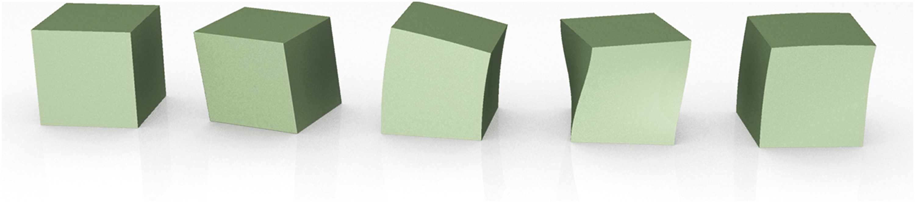
As for occlusion, a study by Previtali 23 outlines the importance of resolving occlusion issues affecting reconstruction quality while at the same time, tackling basic semantics aimed at recovering data to characterize items like doors, windows, walls, floors, and ceilings. It also discusses the undesired occlusion effects that appear when reconstructing geometries from point clouds, which is a recurrent topic.
Jung et al., 24 for instance, acknowledge that voids resulting from occlusion are often smaller than actual window or door openings, a problem that Macher et al. 21 solved by automating the differentiation between occlusion-originated voids and actual openings and then filling the voids with point-cloud patches. The work of Wang et al. 18 acknowledges that such occlusion, being a point-cloud source problem, sets limitations to the outcome of his research.
The tool proposed by Bennis. 25 processes PC_Sets by means of random sample consensus (RANSAC) and Hough algorithms that retrieve wall, window, and door contours grouped as collection of exportable 3D-DXF vectors. Such 3D representations are usable in BIM modelers in the form of wall footprints and placement references for windows and doors. Despite its potential, occlusion issues are unresolved because occluded surfaces turn into voids that usually merge with window and door contours. The works by Hackel et al., Xue et al., Adán et al., and Kropp et al.5,26–28 also mention strategies regarding the challenges generated from occlusion in automated or semi-automated building reconstruction from point clouds.
Throughout the referred works, retrieving building geometry from laser scan data in the form of dense and regular sample points 29 involves using the RANSAC, 30 Hough, Roberts, Canny, or Laplacian algorithms.18,25,31 Other methods, however, appear to tackle similar problems by entailing alternative approaches.
Bassier et al., 32 for instance, propose a “Conditional Random Field” that evaluates the context of each building’s wall in order to determine its position among complex spatial configurations.
Laing et al. 33 use Poisson algorithms to turn point-cloud data into uniform meshes, which are later sliced in order to obtain contour data usable in the Computer Numerical Control machining of mockups. Meshes serve then as a bridge for retrieving geometric building data.
In an approach that uses shell models, in which shells represent building envelopes, Huang et al. 34 retrieve 3D contours from multi-source images for constructing Breps that represent the building’s 3D shape. This method underlines the advantages of using Breps in digital building-envelope reconstruction, mainly because Breps help define roof and facades within the same model. Furthermore, by using a convolutional network (ConvNet) 35 that uses raw inputs rather than hand-crafted features, 36 the work of Huang develops a method for retrieving door and window openings from planar facades. The problem of topology or non-coplanar facades is not addressed by Huang’s work.
With a similar goal—and making use of topologic relations—the work of Huhnt 37 addresses the reconstruction of wall layouts from mesh-generated representations. These meshes are later subdivided into triangle sets and edges suitable for creating three-dimensional non-parametric representations of building components featuring low levels of detail (LODs).
The trend gradually goes from pure image and point-cloud processing to mesh modeling and into parametric NURBS modeling, as strategies for rebuilding geometry from PC_Sets. López et al. 38 pinpoint at least five works that use NURBS modeling as a means for retrieving point-cloud cross-sections that later help in creating the parametric model, aimed at reconstructing the scanned asset. Although at least three of those works claim to make use of the Rhinoceros environment to perform part of the process, they do not disclose further details as evidence.
A procedure developed by Barazzetti et al. 39 slices point clouds in order to retrieve several cross-section NURBS curves that later help in the modeling of complex vaults. Point-cloud profiles are manually extracted later for further processing via an automated NURBS surface 40 generator. 41 Its results show that having several PC_Set slices facilitate the retrieval of topological deformations that result in increased reconstruction accuracy.
Following the same trend, the work of Dimitrov et al. 42 also uses point-cloud slicing as a method to produce cross-section lines later used in reconstructing building geometries. This strategy tackles the building as a whole and does not provide a mechanism for treating parts of it in an isolated manner. As the method is developed within MATLAB, compatibility or expandability toward disciplines other than computing engineering is not clear.
In other approaches, researchers build their work on the retrieval of coarse building geometries that seem tailored for retrieving urban morphologies rather than for façade retrofitting. Such is the case of the works by Mahmud et al. 43 or Guo et al. 44 in which overhead images and tomographic synthetic aperture radar (TomoSAR)–generated point clouds help construct tridimensional representations of building blocks of a given urban landscape.
Most of the previously mentioned methods and studies remain close to the goals this work seeks to reach, which demonstrates that the topic is of interest and in constant evolution. It also shows that several research endeavors cover aspects not usually developed by industrial solutions like FARO As-built, 45 Scan to BIM, 46 Scalypso, 47 or Leica Cloudworx. 48 These industrial solutions offer reliable tools for most standard reconstruction cases. However, they do not provide accurate solutions for retrieving topology “as is.”
This is where this work seeks to generate a contribution to the field.
Research aim
Point-cloud deconstruction and segmentation has been widely explored in recent years, since the use of PC_Sets for architectural surveying has become commonplace in mid-size and large renovation and retrofitting projects.12,13 This work aims to provide a point-cloud–based surveying method utilizing the Rhinoceros–Grasshopper environment (RGH). The referred method uses a topology-based tool that retrieves 3D contours usable in digitally driven retrofitting endeavors.
The parametric modeling workflow 49 utilizes RGH along with plug-ins and custom scripts whose purpose is to deliver the three-dimensional contour of a given building. To validate the approach, we conducted a test on a building whose stories do not share coplanar facades; thus, facade planes are not continuous.
Furthermore, the three-dimensional outcome (as a common file format) is thought to be interoperable with specialized software for exterior insulation simulation and nesting. To this extent, all the user needs to process PC_Sets is a point-cloud editor such as Autodesk Recap Pro 50 or CloudCompare 51 and a recent version of RGH.
As for data including the building’s structure, the amount of retrieved geometry depends on how concealed structural elements are. Structural concealment is more frequent in framed structural systems than in wall-bearing systems, although this fact is not a constant.
Scope and limitations
Considering the cited aims, the works presented in this article cover a real case study whose characteristics integrate challenges like occlusion, topology, and reflections that affect laser scanning (because of glazed curtain walls). However, as the aim is to give a proof of concept, this case does not yet represent a very complex scenario, which opens an opportunity to develop other case studies within less favorable contexts. As it will be explained in coming sections, the GH solution performs well when tackling orthogonal facades.
Although retrieving heterogeneous contours is a capability that the solution should fulfill without difficulty, retrieving contours from openings over-curved or twisted facades, for instance, remains a challenge that needs to be addressed.
Methodology
As the purpose focuses on the extraction of three-dimensional contours of building envelopes from unstructured PC_Sets, point clouds are treated in the same manner as they would be within BIM modelers such as Revit, Archicad, or ALLPLAN.
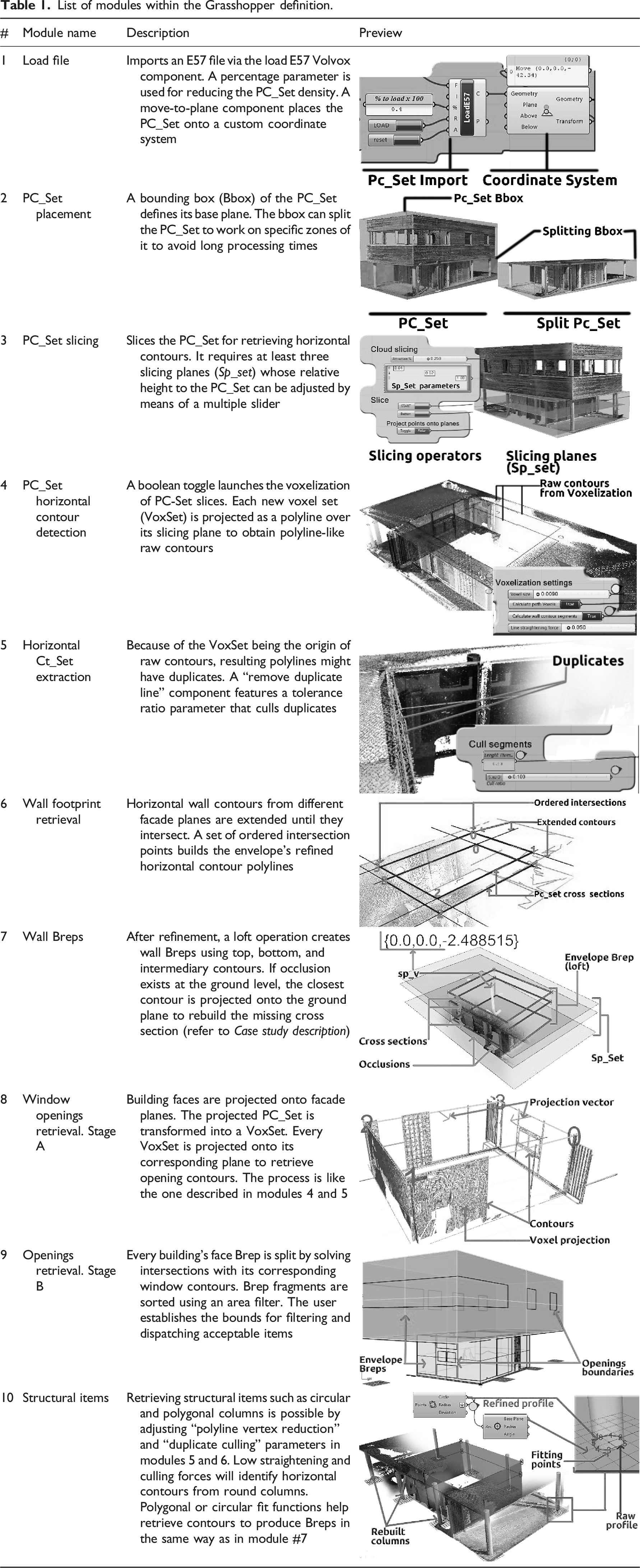
List of modules within the Grasshopper definition.
Case study description
The context for testing our method consists of a two-story house whose first and second floor facades are not coplanar. It is characterized by aspects like: Facade walls belonging to the first floor are made in concrete, whereas the second floor’s envelope is a composite wall with an exterior wood siding. Facades possess standard windowing and facade curtain walls. The latter often turn into a challenging item when performing contour recognition from point clouds because of the presence of thin boundaries belonging to mullions. Despite the fact of having the shape of a box, the problem of topology, as in most buildings, is present. It is mainly found in the siding because of the shrinking and bending of wood planks. The wooden siding adds noise to the point cloud. That means that there is an amount of “floating points” gravitating close to the facade plane.
The point-cloud acquisition process was performed using a FARO Focus 150 terrestrial scanner at a resolution of 28 Mpts along with the FARO Scene software, 53 which was used for registering scans. The post-processing of the registered point cloud was performed using Autodesk Recap Pro, from where the point cloud was exported as an E57 file, which is one of the formats accepted by DURAARK’s Volvox plug-in for GH, 31 whose role is described in coming sections.
The environment is a university campus composed of several buildings, from which the janitor’s house is the one that resembles a common retrofit problem the most. The house is characterized by a simple architectural approach: two regular volumes whose size varies, so the global volume is not regular, and facades are not coplanar (Figure 3). Janitor’s house. Left, the actual house. Right, point-cloud set.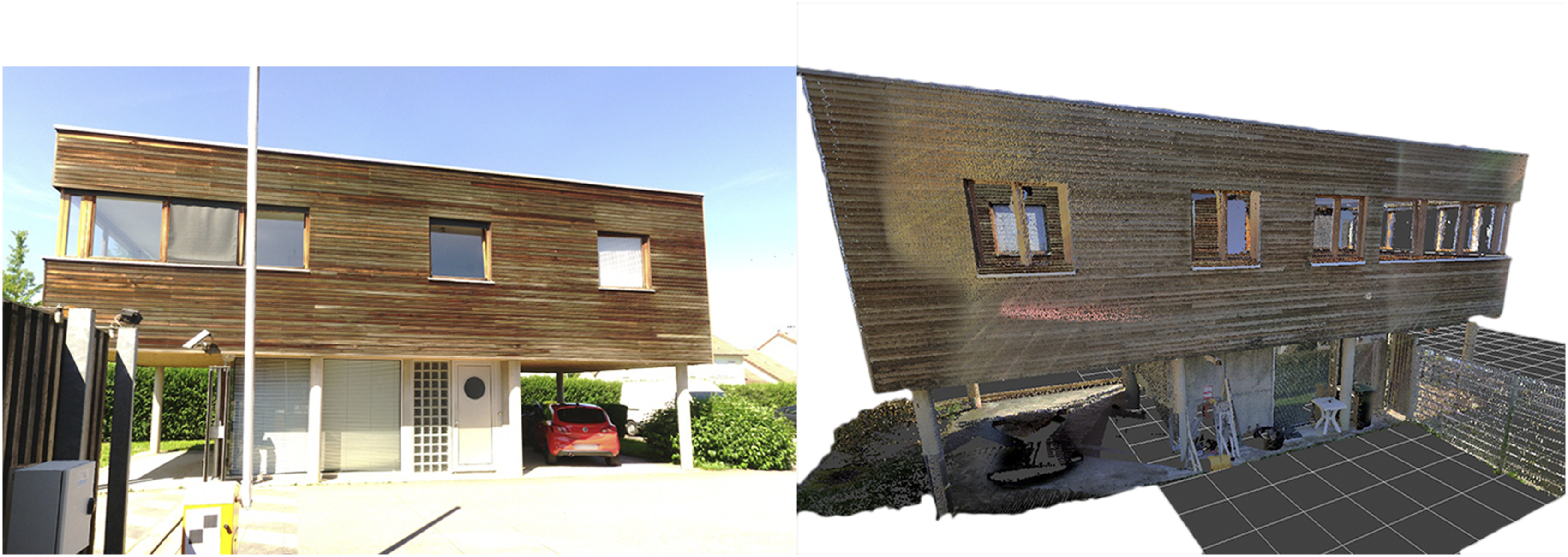
The occlusion scenario is characterized by the presence of vehicles and items belonging to the property (first floor), along with exterior window screens that create noise and occlude window frames. Fourteen scanning stations were necessary to create the point-cloud data used in this test.
Workflow
As shown in Figure 4, the process starts by importing a PC_Set fetched as an E57 file whose density can be reduced to improve the system’s performance, since the PC_Set undergoes several further transformations into voxel sets (VoxSet). General method and Grasshopper definition workflow.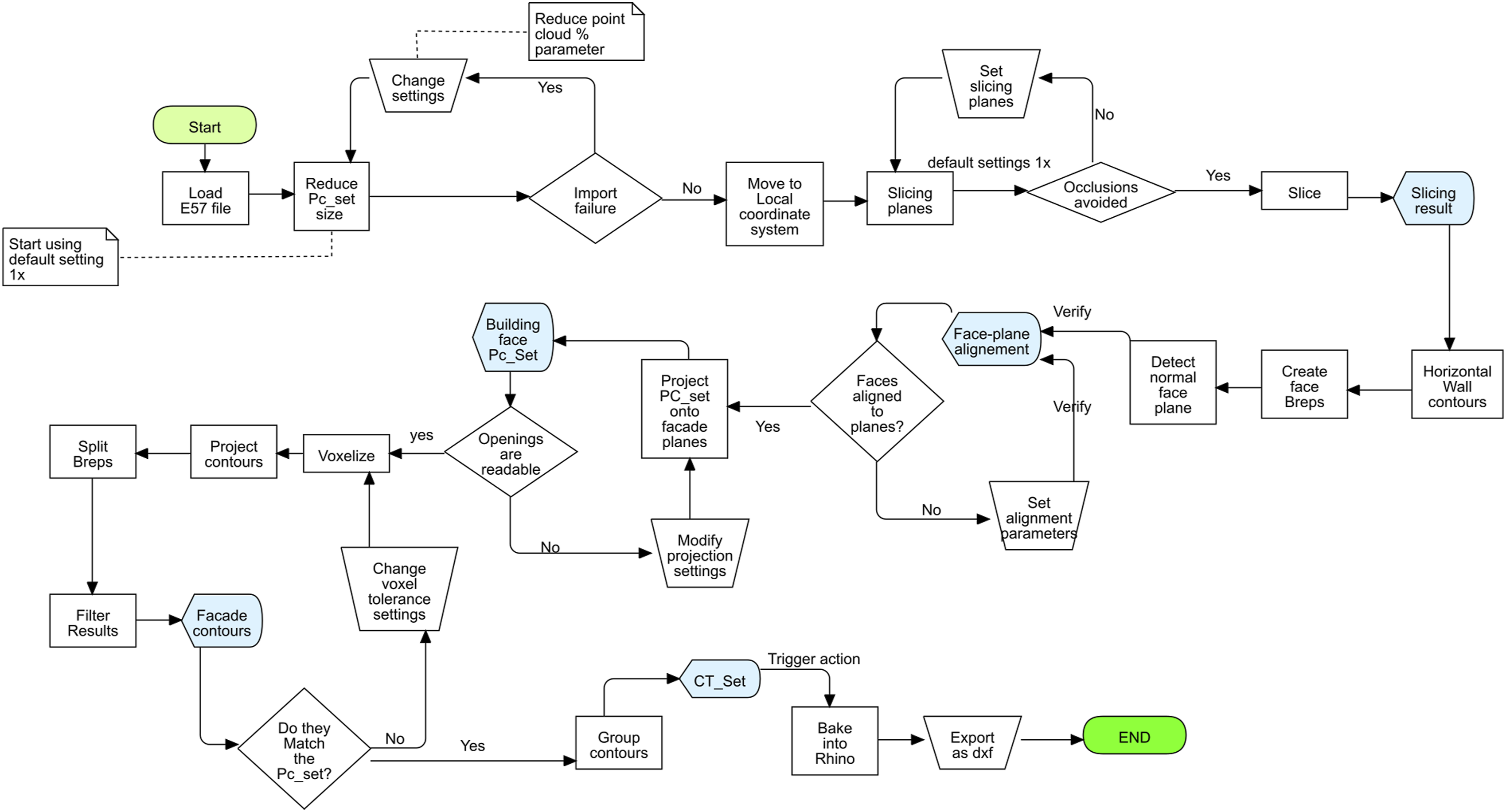
As PC_Sets often have their own coordinate systems, the GH solution provides a mechanism that places the point cloud onto a locally defined coordinate system, which is achieved by translating the point cloud to a reference plane defined by the user (Table 1, #1).
The PC_Set is then intersected by a set of slicing planes (Sp_Set) that produces cross-section contours
54
or contour sets (Ct_Set). These Ct_Sets will be used later for reconstructing each of the planes, parallel to every building’s face (F_C_Plane) (Figure 5). As occlusion appears to be an important issue when reconstructing building geometries out of point clouds,23,24,54 the user can use a multiple-entry slider in the RGH definition to adjust the relative height of each plane comprising the Sp_Set to skip occluded regions (Table 1,#3). Left, point-cloud set (PC_Set); Center, slicing planes and PC_Set cross-sections. Right, envelope Brep after reconstruction and building face construction planes (F-C_Plane).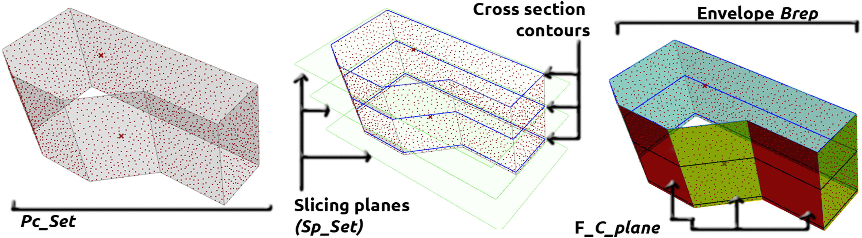
Because occlusion mostly occurs at levels close to the ground, the possibility of having missing point-cloud set (PC_Set) regions might induce an error when detecting the footprints of envelope walls. In such case, the Sp_Set computes a vector (Sp_v) by connecting origin points retrieved from the top and bottom planes of the Sp_Set, which in turn will project a substitute footprint for walls affected by occlusion (Table 1 #7).
Unlike wall footprints, retrieving boundaries for windows and doors is achieved by projecting segments of the PC_Set onto their corresponding facade construction plane (F-C-Plane). After facade planes are detected, a first-degree NURBS surface 40 containing face boundaries (Breps 2 ) is created using the F_C-Plane as reference. The user employs the same F-C-Plane as an attractor to project a certain quantity of points from the PC_Set onto the Brep, so openings are clearly readable on the screen. After a voxelization process, a boundary polyline—which is later refined to cull undesired vertexes to smoothen resulting contours—is created for each building’s face (Table 1, #8).
The GH solution uses openings contours that split the facade Brep to obtain a geometric 3D representation of building facades (as Breps). Constituents of such Breps are then extracted to retrieve final contours, group them, and then bake them into Rhinoceros prior to exporting them as a 3D polyline set, which is the final output (Table 1, #9). Module description describes in further detail each of the modules composing the RGH definition.
Module description
The 10 modules depicted in Table 1 perform the following operations: import PC_Sets; assign PC_Sets a coordinate system; Slice PC_Sets; retrieve wall footprints (horizontal contours); retrieve wall heights; create Breps from wall footprints; retrieve facade openings (windows, doors, curtain walls, and empty openings); retrieve column contours, Breps, and group contours; and export them in a compatible file format.
The results shown so far are the products of testing the GH solution against a complete PC_Set from an actual house. Partial tests with other point clouds were performed in order to refine the solution’s parameters so that when using it in the case study, it would be possible to measure the time it takes to process an entire PC_Set. The PC_Set used for testing the GH solution had about 12.8 million points that were reduced to 5.13 million before running the GH algorithm.
The observations show that with a PC_Set that size, most processes react within a time range between 200 ms to 400 ms, although there is an exception. Calculating contours from voxel projections takes up to 2 min when applied to the second floor and up to 4.5 min when used for the first floor. This might be caused by the presence of higher point-cloud noise in the first-floor segment.
The described process delivers a three-dimensional contour set (Ct_Set) representing the building’s envelope. To set a use scenario, the obtained contours were transformed into IFC entities directly within RGH. The process is depicted in the next section.
Generation of BIM entities
As there is an increasing use of BIM in the AECO industry, several solutions, allowing export of building geometries as IFC files, exist. Such is the case of the RGH environment for which various BIM-aimed add-ons like Grevit, 55 GeomGym IFC, 56 or VisualARQ, 57 which help translate architectural shapes into IFC-compatible models, are available. In more recent developments of Autodesk Revit, it is possible to run RGH “within Revit’s memory space,” 58 thus increasing interoperability and workflow flexibility.
Although creating BIM-compatible entities does not constitute the main goal of this work, providing a strategy to convert 3D building contours into IFC data might help understand the usefulness of this PC_Set slicing method. Aside from the main goal, which is to create 3D boundaries for facade retrofitting, this information can be used to create As-Built 3D models exploitable in O&M and building management.
Depending on the intended use, as-built 3D models generated as result of this strategy can be enhanced using a BIM native modeler. Through a native modeler, it is possible to add information regarding building components’ life cycle, building maintenance cycles, physical properties, mechanical properties, site information (location, altitude, and weather), and building occupancy to cite a few examples. Moreover, these BIM models can help in the planning of the retrofitting operation by anticipating the logistics and possible conflicts with its occupants 59 and then help monitor the operational efficiency of the retrofitted asset. 60
A test using GeometryGym’s plug-in for RGH, GeomGym IFC, was performed. The plug-in helped in creating parametric IFC entities that are later suitable for exporting as a 2 × 3 IFC file. While GeomGym IFC provides the necessary tools for creating building components following the levels of decomposition defined by the IFCSpatialStructureElements supertype,61,62 the 3D building contours obtained using our method provide an accurate basis for generating building geometry. This is because GeomGym IFC mainly requires lines and reference points for creating IFC entities (Figure 6, left). IFC model generation from 3D contours. Up, model hierarchy. Left, 3D building contours. Right, IFC elements within GeomGym IFC. IFC: Industry Foundation Classes.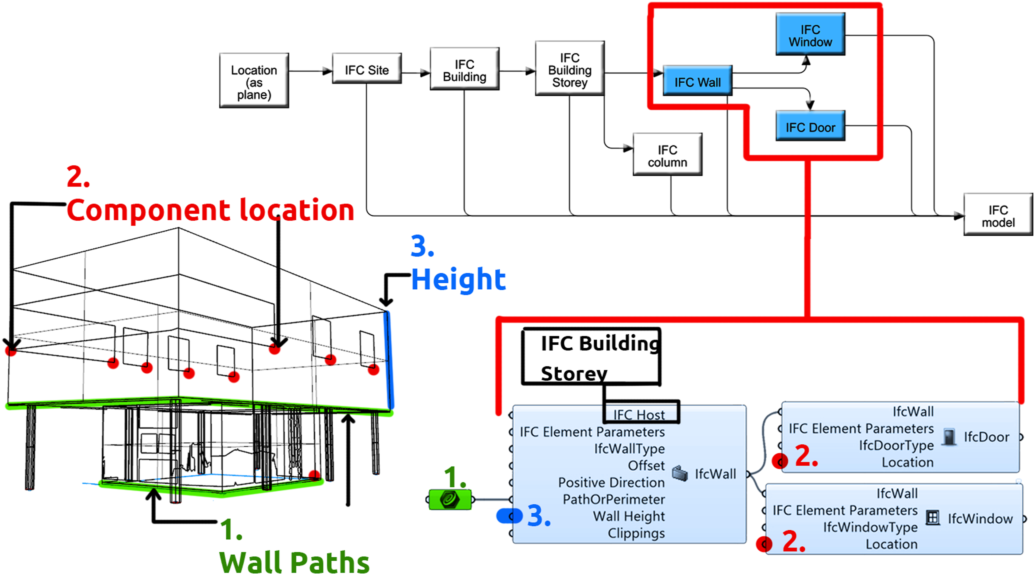
3D contours were decomposed into their basic elements using standard GH components, which in turn allowed the retrieval of building data in the form of reference planes, building and story heights and placements, dimensions and positions for openings, and walls and columns (Figure 6, Left-Right).
Please notice that although the graphical representation looks acceptable, erroneous IFCElemenParams are not graphically displayed; therefore, an erroneous model is not visible. Usually, IFCElemenParams errors are detected after exporting the file and opening it with an IFC viewer or native BIM program, in which case there will be missing elements, disaggregated entities, or no entities at all.
It is advised to check IFCElemenParams before exporting them to detect errors. For more information about the correct utilization of GeomGym IFC, we encourage the reader to test GeomGym IFC according to the documentation provided by its developer. The performed test yielded a LOD 100 model whose IFC file reads well in Revit
63
and Archicad
64
for further enrichment (Figure 7). Left, 3D model as obtained from RGH. Right, enriched model using Archicad.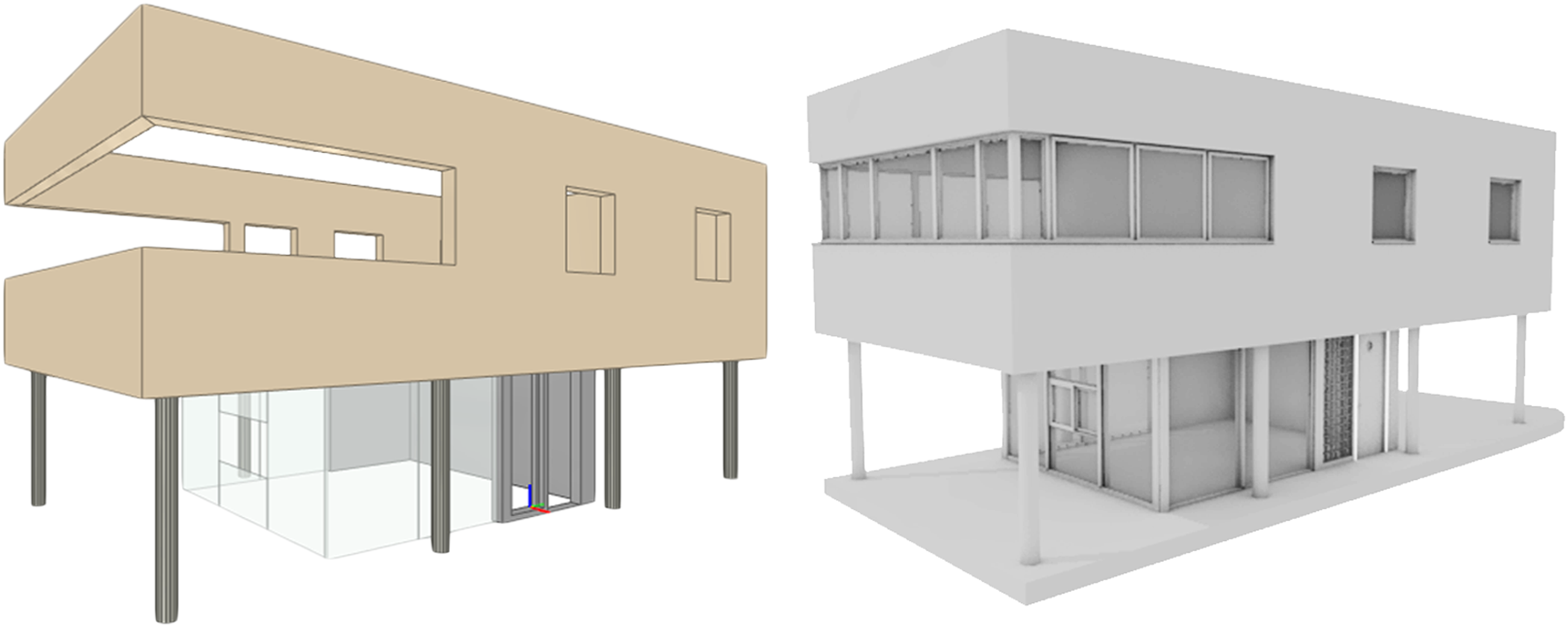
Discussion and results
The workflow and the methodology presented in Methodology provided the tools for assembling a flexible GH solution, whose purpose is to retrieve as-built 3D contours usable in facade retrofitting endeavors.
In the end, the proposed method and its GH definition not only provide a strategy for translating point-cloud information into geometric data but facilitate the application of a building renovation trend that tackles both operational and embodied emissions. By encouraging energy and structural retrofitting, these initiatives might help in delaying building deconstruction, therefore reducing the index of embodied emissions of the retrofitted asset. 65
The achieved results show that the proposed method, along with its RGH definition, can produce three-dimensional Ct_Sets from point clouds that are usable in facade retrofitting projects (Figure 8). By deconstructing PC_Sets using parametric NURBS modeling, it is possible for the user to have a feedback from the solution and progressively adjust its settings as needed. Left, illustration of the transformation of the PC_Set into a Ct_Set. Right, 3D contour set (Ct_Set).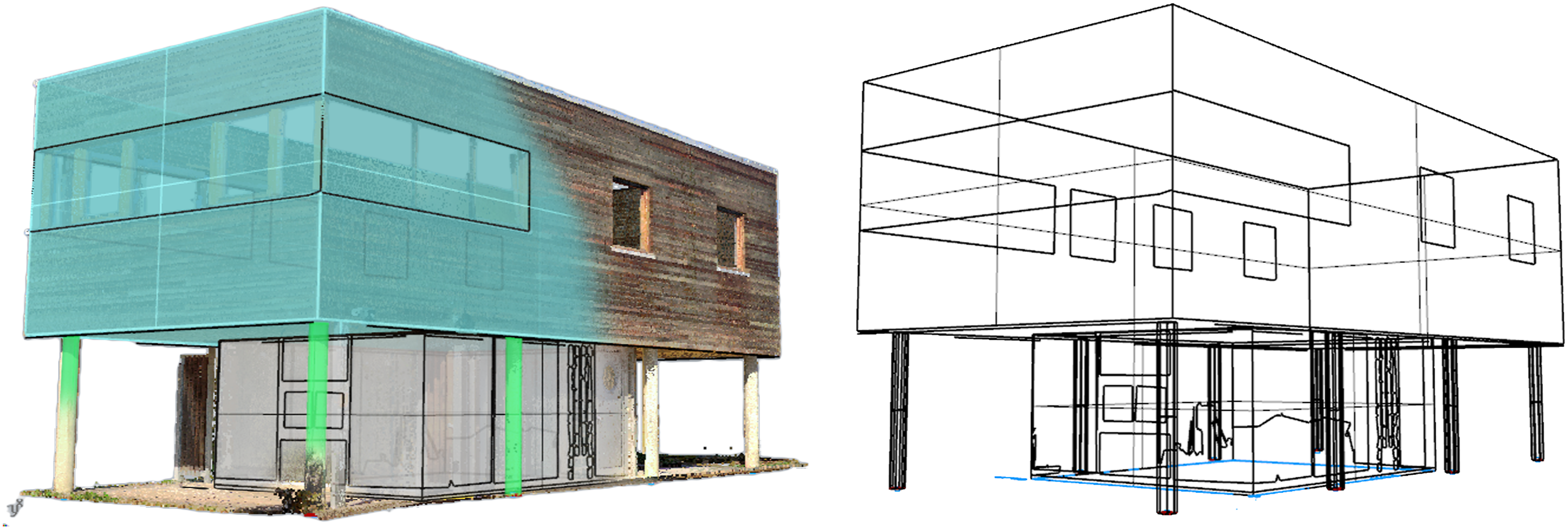
The modules within the GH definition were tested in the reconstruction of a building’s envelope whose stories do not possess coplanar facades and whose ground floor facades are affected by random occlusions, mostly at the ground level.
The general functioning of the RGH definition yielded several of the expected results. The most relevant are: Importing and downsampling PC_Sets for improving computing times. Splitting a PC_Set, so non-coplanar envelope segments are reconstructed separately and then regrouped into a single 3D Ct_Set. Developing a strategy to avoid or bypass PC_Set occlusions commonly found when scanning building envelopes. Proposing a modeling workflow capable of reading building topology instead of limiting the solution to solving regular-parallel building topologies. It is achieved by implementing footprint extrusion and loft operations applied to horizontal envelope wall contours. A test using the GeomGym IFC plug-in for GH allowed sketching a digital workflow for transforming three-dimensional Ct_Sets into IFC-compatible models suitable for enrichment via native BIM modelers such as Revit or Archicad.
Furthermore, as the GH solution was being tested some improvement and development opportunities appeared.
First, it was found that the quality of the PC_Set has a heavy incidence in the voxelization of PC_set slices, which also affects the generation of horizontal contours. The problem lies in the length of wall cross-section segments that result from module #4 (VoxSet). The shorter the length of cross-section segments, the bigger the risk of obtaining a deviated horizontal wall contour, which can cause a warped facade or distorted opening contours. An improvement to address this problem is envisaged.
Moreover, the ability of the GH solution for reading and rebuilding topology from the PC_Set is limited and needs further work. So far, the GH algorithm can address shearing and bending topologic deformations. However, several tests are still necessary to improve the results in buildings featuring other types of topology (i.e., twisting or tapering).
Accuracy
Accuracy is an important aspect to consider when tackling facade retrofitting projects. The RGH definition accompanying the method proposed herein includes an accuracy-measuring module that evaluates the minimum and maximum distances between a sample point in the PC_Set and a given wall cross-section over a slicing plane. It calculates the average distance between both entities, the wall footprint, and the PC_Set sample point to provide the user with information regarding potential deviations.
At this point, the user can check whether facade planes (F-C_Planes) are: Within a range inside the PC-Set slice (PC_Set_a), so the user can verify if reconstructed building faces are properly placed on the corresponding XY plane. Aligned to the PC_Set segment being measured. This is possible by taking measures on different slicing planes, which in turn are placed at different relative heights. While the measured segment itself helps identify horizontal deviation, assessing the same criterion at different relative heights ensures the face Rrep will follow any pre-existing topology the facade might have.
How it works
The measurement tool populates a wall footprint (Wp1) with a given number of sample points (Sample_Pset) which in turn are tested against the VoxSet segment to which Wp1 belongs (Figure 9). It uses an “RGH closest point”
66
component that measures the distance between sample points and their closest point in the VoxSet (Figure 9, right). Figure 9 shows that a wall footprint (Wp1) is measured against a VoxSet segment (VoxSet_a). Accuracy test—Left, sample measuring. Right, sample point set and distances around a random sample point for measuring. Sample points are measured against a VoxSet from which wall footprints are retrieved.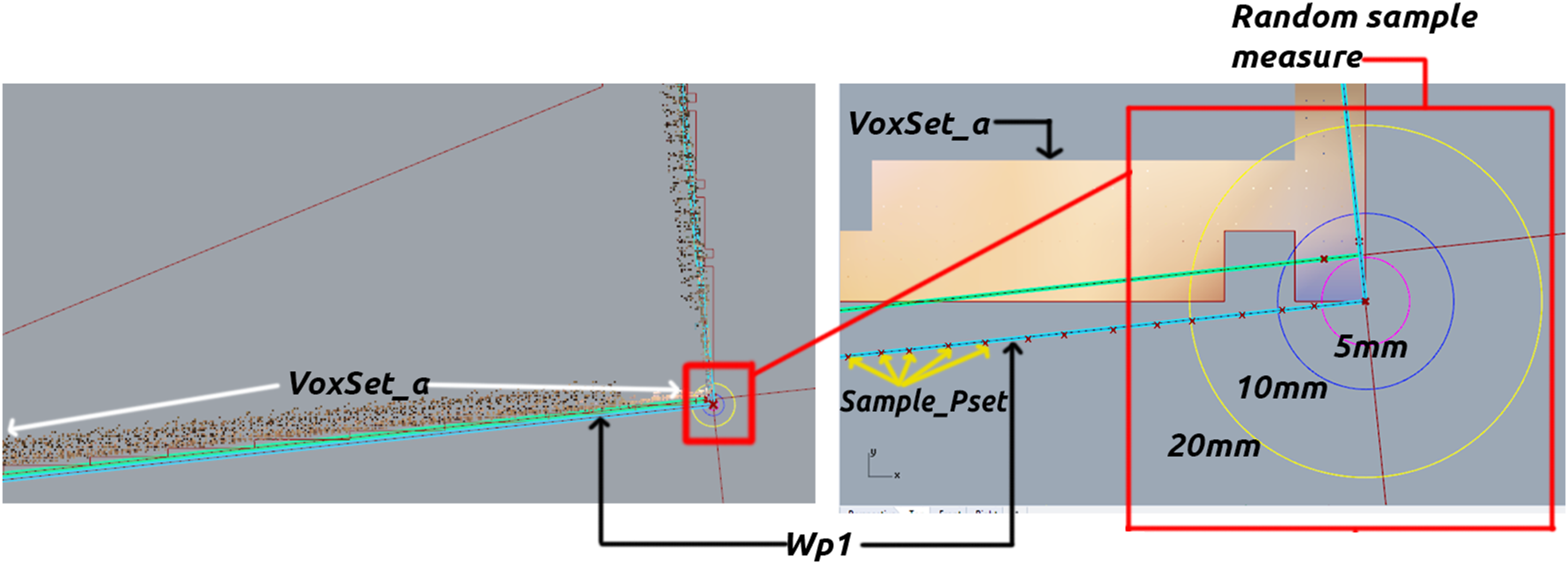
According to the graph in Figure 10, about 51 sample points are within 2.9 mm and 10 mm from their closest point along VoxSet_a. Only eight are in a range between 10 and 13.5 mm from their closest point. Accuracy measurement tool. 1 Wall footprint set (as tree), 2 wall footprint selector, 3 sample point creator, 4 PC_Set closest point component, and 5 and 6 measurements.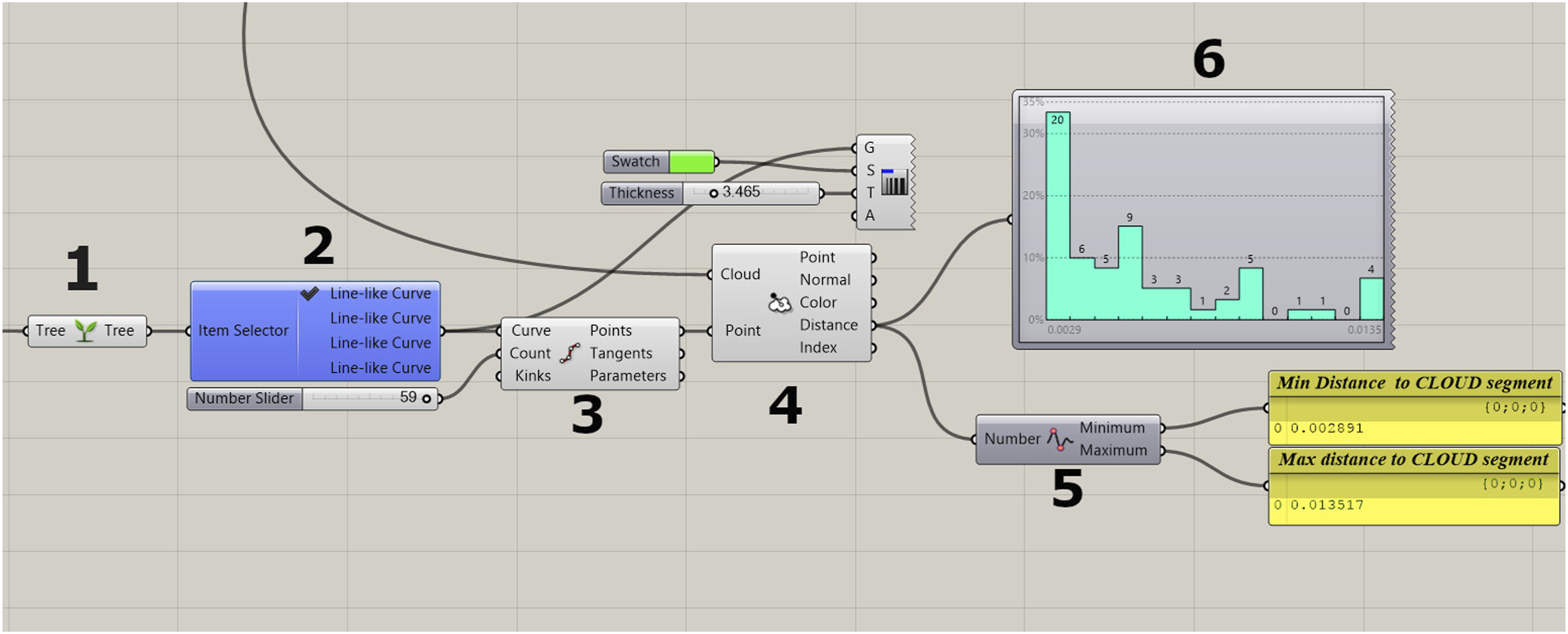
This function’s purpose is to provide data, supporting accuracy metrics during the digital reconstruction process.
Conclusion and research perspectives
In its current state, the GH definition can slice the PC_Set of a building envelope to obtain wall footprints that later help generate a NURBS representation. The advantage of slicing the point cloud to do this lies in the fact that voxelizing small parts of a point cloud takes less time than processing the entire PC_Set.
Furthermore, it is easier to detect empty spots in horizontal planes affected by occlusion, for which the user can decide to displace one or several slicing planes or to project horizontal contours onto the ground plane to bypass occlusion. Moreover, this methodology uses semi-automatic modules that combine the computing power of parametric modeling with the expertise of the user, thus leading to more accurate, flexible, and explainable “human-oriented” tools.
The same slicing method is used to retrieve window and door openings in the form of Ct_Sets that later help split the envelope’s Brep. By running a series of operations, contours are regrouped in a manner that they represent finite facade components: envelope walls, windows, doors, and even columns. As a work in progress, this method has potential for reconstructing freeform building geometries, which is an important limitation of RANSAC-based methods that depend on PC_Set fitting planes for retrieving building contours.
The resulting Ct_Set constitutes a valuable set of geometric data usable for facade retrofitting projects in which accuracy is crucial. A further step in exploiting the 3D Ct_Set showed that it is also useful for producing IFC files suitable for further BIM enrichment.
Upcoming development stages will aim to improve functions regarding topics such as: Occlusion. So far, the proposed method can tackle some occlusion cases, which means more testing is necessary to document more occlusion scenarios and develop strategies to solve them. Wall footprint detection. As mentioned before, this stage needs to overcome PC_Set quality issues. Building topology. More work is envisaged to tackle not only complex buildings but also manifold facade layouts since the performed tests work well when dealing with relatively flat facades (so far). This means facade components such as cornices, sills, casements, keystones, pilasters, and rails, among many others, or even curved facades, still need to be tested against the capabilities and possibilities of the current solution. We acknowledge that such topics remain a challenge in the digital reconstruction field since some of the cited works lack capabilities for resolving them too.
Footnotes
Declaration of conflicting interests
The author(s) declared no potential conflicts of interest with respect to the research, authorship, and/or publication of this article.
Funding
The author(s) disclosed receipt of the following financial support for the research, authorship, and/or publication of this article: This work was made within the framework of the Digital Sciences Program and the CPER 2015–2020 cyber-companies project, with regional funds from France’s “Grand-Est” through the project grant for “applied BIM-driven strategic and operational cloud services for facilities evolution - UBIK,” and national funds from the DRRT, the CNRS, the INRIA, and the European FEDER project.