




Abstract
Reciprocal frames (RFs) are complex structural systems based on mutual support between elements. One of the main challenges for these structures is achieving geometrical complexity with ease for assembly. This paper describes the development of a new type of connection for RF that uses a single bolt to fix a whole fan. The method used was the Research Through Design, using algorithmic modelling and virtual and physical prototyping. After the exploration of different alternatives, the connection selected was structurally evaluated with a 3D solid finite element analysis (FEM) software and a 2D bar parametric model. Finally, a full-scale pavilion was built as a proof-of-concept. A total of 47 connections were fabricated using four 3D-printed templates combined with a hand router. The construction allowed us to draw conclusions on the connection design and the assembly method, and the process as a whole can contribute to the development of new structural links and production methods.
Introduction
Reciprocal frames (RFs) are made of mutually supported linear elements in a way that they can be easily assembled to form large structures, even when each element is short. Used since thousands of years ago as temporary, portable structures, made of interlocked timber elements, but also as permanent structures as the Zollinger RFs, examples in Japan in 1990s as well as many centuries of vernacular planner timber RFs especially used for floors when the available timbers were shorter than the span they needed to bridge. RFs progressively became subject to technological improvement and scientific research with the availability of digital tools that enable fast and easy geometry definition and structural behaviour understanding. Nowadays, RFs are seen as an opportunity to build more sustainable structures, due to the possibility of employing short elements, such as salvaged, left over or repurposed timber pieces.
RFs are characterized by (1) their structural elements (nexors) and (2) the link between them. Nexors can be as simple as wood sticks or made of metal profiles or sawn timber, typically with circular, square or rectangular cross sections. They can also be made with plates. Primitive RFs relied solely on friction for connecting nexors, but as these structures became bigger and safety concerns arose, new types of connections have been developed.
The present research aimed at developing a new RF connection that fulfilled the following requirements: Can be applied to a variety of global forms, including complex surfaces; Embeds geometrical complexity of the structure, allowing the nexors to have simpler shapes and identical length, even for complex global geometries; Provides easy assembly and disassembly, allowing for reuse of the structure more than once; The extra weight of the connection is minimized to have less impact over the structural performance or the assembly process; Does not weaken the nexors, making better use of materials; Allows the use of a variety of timber products and sizes, thus facilitating the use of repurposed or waste elements.
In order to meet the objectives above, the research had to answer the following questions, related to the new connection’s structural performance, feasibility and sustainability: a. Which are the impacts of the new connection to the strength of individual parts and to the global stability of the structure? b. Can this new connection be easily mass-produced/mass-customized? c. What sizes and types of timber products can be used and are those easily available as industrial waste?
Review of RF connections
Previous research conducted on the topic allowed us to gain a better understanding of RFs and their different types of connections. RF origins and development through history are presented by Larsen, 1 while a critical overview has been conducted by Pugnale and Sassone. 2 Castriotto et al. 3 identified critical issues for the development of RF structures that still need to be addressed.
Rizzuto and Larsen 4 studied the structural performance of three types of connections used in RF and mutually supported elements (MSEs) built with circular cross section bars, assessing their advantages and disadvantages. They analysed friction connections with swivel couplers, bolted connections and notched connections (which, in timber, can be combined with mechanical fasteners and/or structural adhesives). The authors 4 concluded that ‘the use of notches along the length of an element weakens it in bending due to a reduction of the cross-section’ and that ‘notches at the end of an element will produce a reduction in shear capacity’ (p. 250). They suggested that further experimental and numerical investigations were required to better understand the structural behaviour of RF bolted and notched connections. Moreover, a downside of bolted connections is recognized as the fact that they increase shear forces, which timber is less resistant to.
Gustafsson
5
proposed a categorization of RF connections, specifically for horizontal planar grids made of rectangular cross section timber beams. The connections were grouped as (1) superposition, (2) couplers, (3) dowels and (4) notches. The author classified each type according to production, assembly/disassembly and reuse, appearance and structural properties. The coupler’s type was then subdivided into lashing, contractible clamps and joist hangers. Contractible clamps work by ‘increasing the friction grip to transfer load’ [5: p. 18], at the same time that they do not damage or reduce the bars cross section properties.
2
However, the type of clamp used by Gustafsson
5
(Figure 1) only works for planar surfaces. More studies would have to be carried out to understand its applicability in other geometries. Coupler connection with a clamp-like connector. Source: Gustafsson [5: p. 18].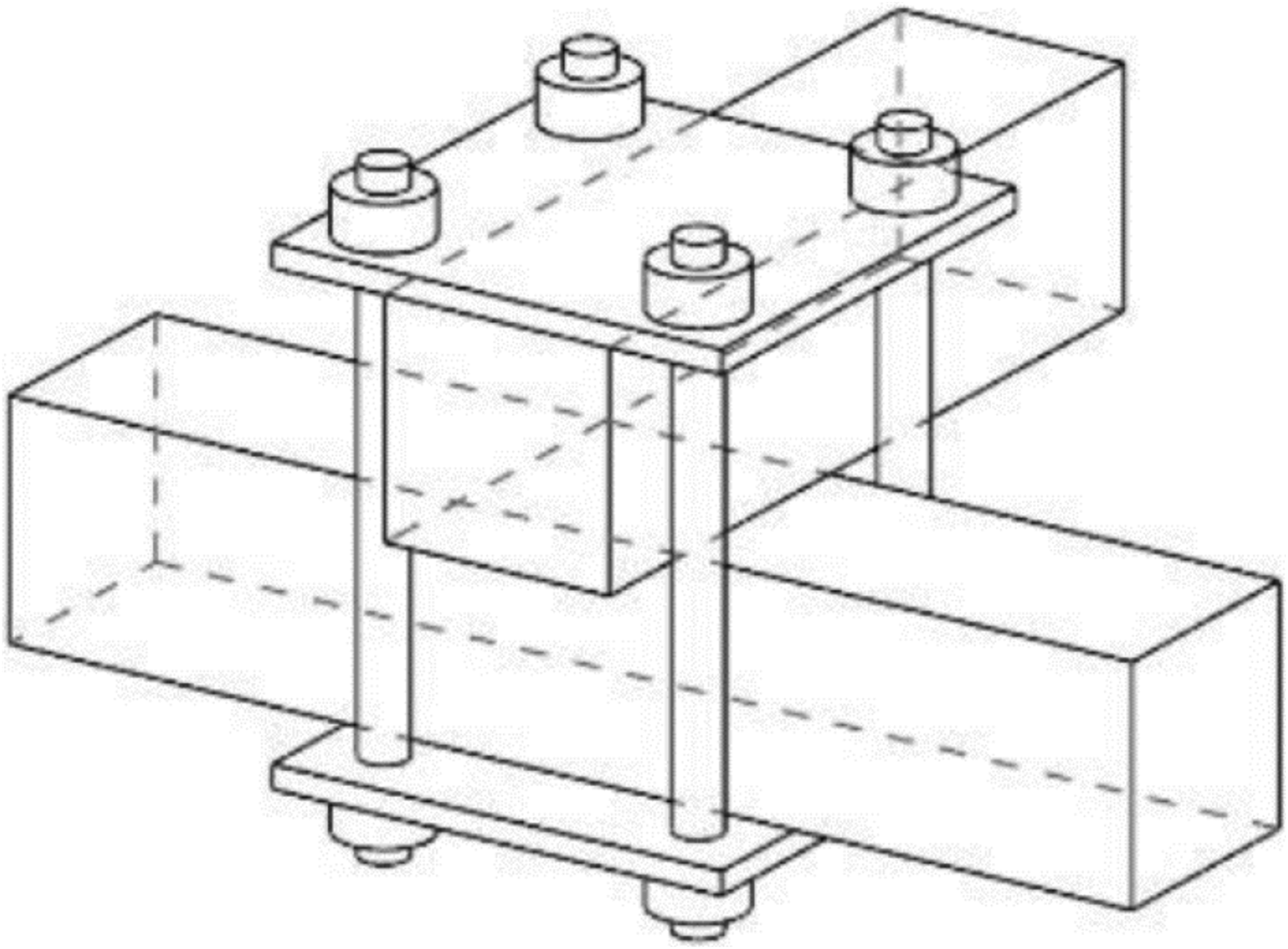
Another type of RF connection found in the literature, but with rare applications, is the solid window, as texplored by Gheorghe and Vierlinger.
6
In RF, fans are the areas where three or more nexors meet together. The window is the hollow space inside the fan, defined by the nexors’ engagement lengths, as shown in Figure 2(a). They
6
have developed a RF structure in which the windows are filled with a polymer concrete (Figure 2(b)). (a) RF fan parts and (b) RF solid fan connections. Sources: (a) the authors, 2021, and (b) image edited from Gheorge and Vierlinger [6: p. 5].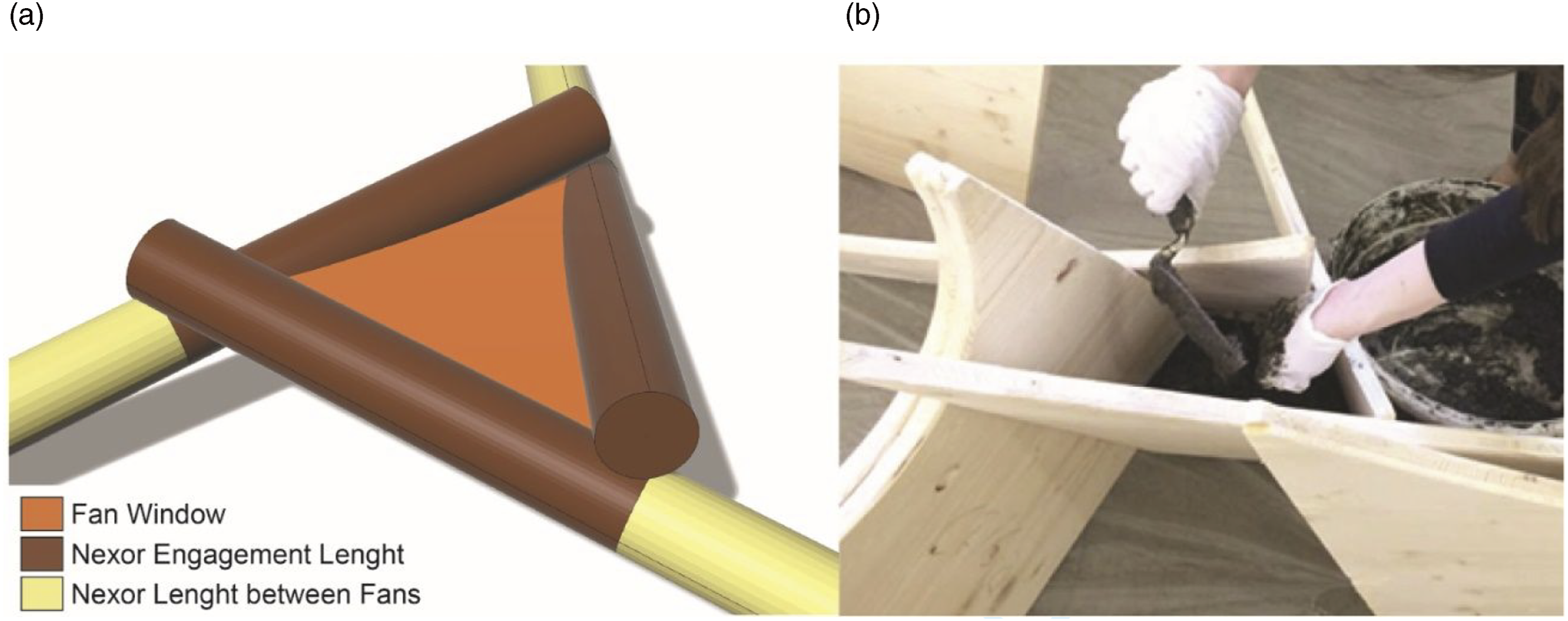
This system has the advantages that it can be used with any surface curvature angle and that it stiffens the angular connection between the nexors. Besides, since the nexors’ engagement lengths are glued to the solid window, without any fasteners or notches, they are not weakened by holes or cuts. Inspired by the connection methods mentioned (clamp 5 and filled fan 6 ), the one presented in this paper mixed some of their best qualities in order to create a new one that fulfilled the proposed aim.
Method: research through design
Reflexive professional activity and scientific research have different natures and require distinct methods. While scientific problems can usually be solved through deductive reasoning, professional activities, such as design, often deal with wicked problems that are difficult to structure and to formalize, requiring abductive, imaginative methods. The purpose of research is the production of knowledge that can be abstracted, generalized and used by others in different situations, while the purpose of design is to develop a specific solution to be applied right away. 7 Yet, the process of design can be valuable and reused in other design problems, too.
After the 1950s, many professional areas started to incorporate scientific methods to their practices, in order to gain academic credibility. 7 Design was seen as too intuitive, therefore, not reliable. Herbert Simon 8 was one of the pioneers in rescuing the value of design methods and in understanding design’s own underlying logic. His ideas influenced a number of formal methods, such as Design Science Research (DSR) 9 and Research Through Design, which are nowadays used broadly, for example, for increasing the solution space, driving novelty and increasing the ability to solve unexpected problems. The innovative design process is nonlinear and iterative and can be enhanced by strategies such as analogies and the recombination of existing concepts. 10 In the design process, virtual and physical prototyping are acknowledged as important facilitators. Since the early 2000s, algorithmic and parametric modelling has also been associated with novel design. 11
In the present research, the study and understanding of existing RF connection types and their underlying concepts led the team to combine two existing principles solid fan and coupler connection in a new one. Moreover, the algorithmic modelling process and the digital structural analysis (virtual prototyping), and the iterative fabrication and assembly processes, contributed to understanding geometrically complex problems and to iteratively testing alternative solutions from different perspectives (structurally, geometrically, aesthetically and from the fabrication point of view). Finally, the construction of a full-scale structure allowed us to face problems that could not have been anticipated in the digital or the small-scale physical prototypes, providing further feedback to the design process.
The whole research was carried out in the following steps: 1) Development of an algorithmic-parametric model of RFs and its application in free-form surfaces. The first step to obtain a new connection system was to understand the relations between the variables that control the structure and the geometry of the voids inside the fans when the RF was applied to different surfaces. 2) Investigate and prototype different connection systems. This step consisted on understanding the functionality of different connection types for RFs. The team started to look specifically at the connection’s detailing, which was developed through digital modelling and physical prototyping, considering the ease for fabrication and assembly. Different connections were developed in an iterative process, until the proposed novel connection type was achieved. 3) Structural models and analysis. Since this discussion is related to a structural connection, it was essential to understand the structural behaviour. Thus, one solid fan connection was virtually modelled and simulated in Ansys, a 3D finite element analysis software. Since the geometry was relatively complex, it required a lot of computational processing power. Then, it was reintroduced in the overall algorithm as an abstraction, that is, in a bar model, emulating the 3D behaviour through fictitious 2D elements. This way, the parametric structural simulation could be done in Karamba. 4) Proof of Concept: using the algorithmic model developed, a pavilion was designed and structurally analysed, using Karamba. The connections were made of waste plywood. A 3D-printed template and a hand router were used to mill them. The nexors were made from leftover timber beams. The pavilion was assembled and stood in an open area for 1 week, before being disassembled.
Design process
One of the challenges for contemporary applications of RF structures is the modelling process. Due to the intrinsic geometric complexity of this system, geometric modelling that is not associative is not suitable for designing these structures. In that sense, parametric and algorithmic modelling seems to be the best alternative to deal with RF complexities. Some methods, tools and algorithms have already been developed as an attempt to facilitate the design of RF structures as presented by other authors.3,12–16 In general, these processes are based on form-finding and bottom-up processes, which often result in the difficulty to control the global geometry.
In order to develop a novel connection solution for RF structures, a different approach was adopted by this paper’s team, starting with the development of an algorithm for a global RF structure. 17 The algorithm allowed us to evaluate the RF structure global behaviour considering the stiffness of a specific type of connection. Importantly, the structural response is given in real time while the global shape parameters are changed. These parameters also enabled a better control over the final structure, which was an opportunity to explore unique and non-obvious possibilities. As for the connection developed, the structural behaviour evaluation was done in separate processes.
Global parametric model
The algorithm developed for modelling RF structures is explained in detail in Castriotto et al. 18 In short, a desired free-form shape is transformed into a quadrilateral structured mesh (quad-mesh), which is then converted into a RF pattern. This parametric algorithm allows the user to have control over several variables at any time in the design process, such as the total number of elements, the cross-section dimensions of each nexor and the 3D angles established between them.
When any one of the parameters is changed, all the interdependent relations are automatically updated. In other words, each parameter has an influence over the final geometry of the structure, allowing to discover unique and non-obvious aesthetic possibilities. The fan and the connection geometries are both defined by a combination of different parameters: the number of subdivisions of the free-form surface by isocurves U and V, the rotation angle of the pattern, and the nexors’ cross-section (height and thickness). To show a glimpse of the possibilities, four different RF configurations applied to the same surface geometry are shown in Figure 3, which were further explored in the Proof of Concept. Four different RF configurations, built using the same surface. By changing a few parameters, such as the number of isocurves U and V, the total of nexors and connections and dimensions change considerably, as it is possible to notice in configurations A–D. Source: the authors, 2021.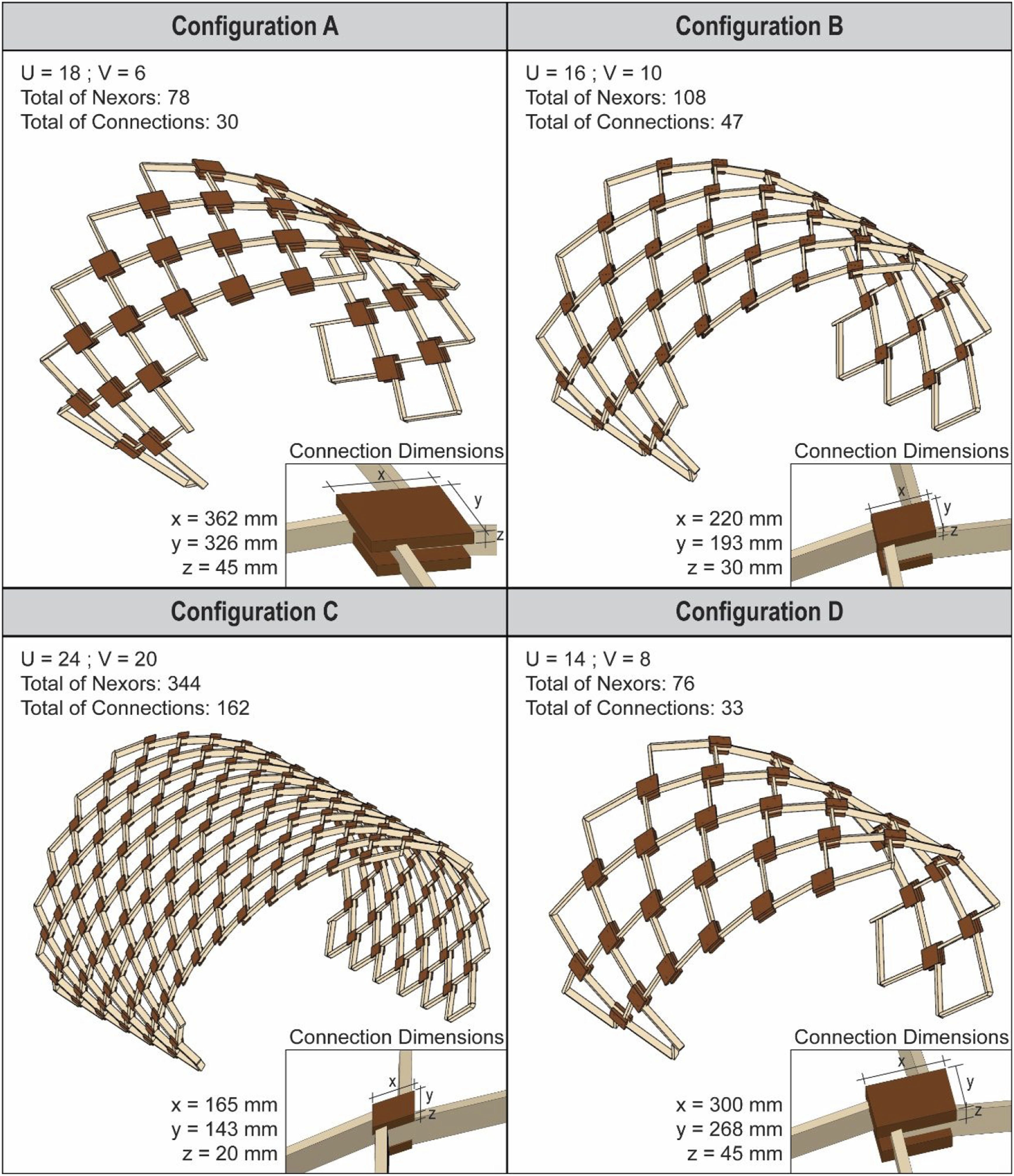
With the availability of structural analysis plug-ins, such as Karamba, inside the parametric modelling environment, these relations can also be explored to understand their impact on the overall structural performance.
Connection investigations
The fact that the fan geometry is a combination of different variable parameters implies the necessity of a parametric adaptive connection system. Based on previous work,2-6 the aim was to develop a connection that would fill the void inside the window fan. In this case, to ensure that the geometrical complexities would be embedded in the connection elements, all the relations established between them and the nexors were automated in the parametric model. There were a total of four iterations to develop the idea from the filled void to achieve its final version (Figure 4). Each one of them was modelled and the feasibility was verified by prototyping and assembling. Diagram showing the evolution of the prototypes, from the idea of filling the fan empty space to the development of the clamp connection. Source of photos a, b, c and d: the authors, 2020.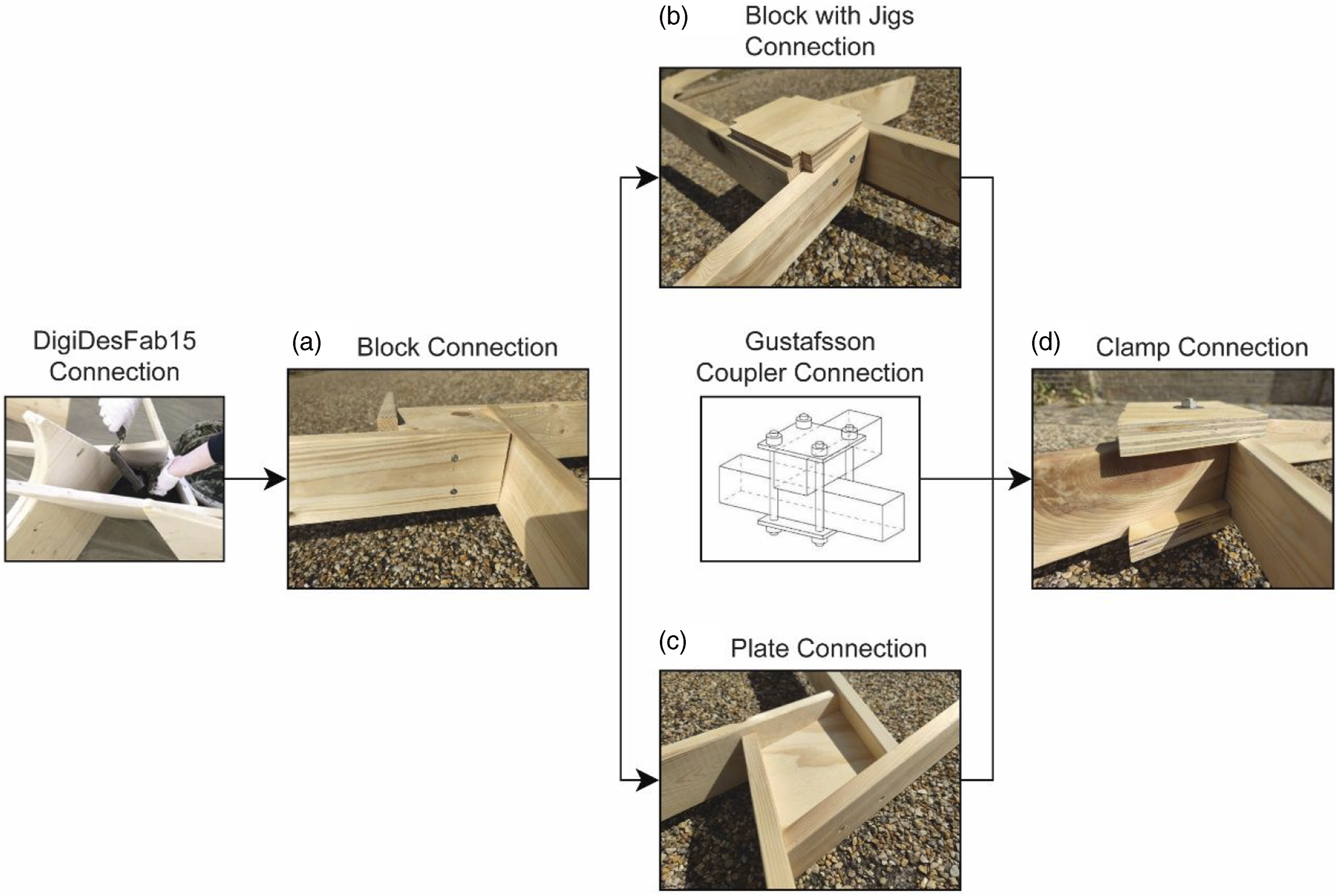
The initial idea was to fill void space in the window fan using a solid block of wood (Figure 4(a)). The virtual model was easily made but the mass production would require at least a 4-axis CNC, due to the angles made in the four sides of the block. The real challenge came when the assembly process was tested. This connection required 16 precision markings for bolting, eight in the nexors and the other eight in the block. Since there were no guides or auxiliary elements, positioning the nexors and the connection in the right angle also demanded a lot of effort. Nonetheless, the overall weight of the fan increased considerably due to the dimensions of the connection. The feedback of this prototype was the necessity to develop better strategies for assembling a fan and reducing the weight.
The addition of the jigs in the block connection (Figure 4(b)) helped to align and set up the nexors position in order to bolt them, reducing the overall assembly time of one fan. From a more aesthetic point of view, the geometry still required more refinement. The disadvantages of this typology were 1) higher weight due to the metal pieces, 2) bolting generated high shear stresses in nexors and connections and 3) the assembly process still required drilling and precise markings. The plate one (Figure 4(c)) had the objective of reducing the maximum amount of material. Because of that, it was the lightest connection developed but also the hardest one to bolt. The required precision for positioning, marking and bolting was even higher than in the first one, due to the thickness of the connection, which resulted in the slowest assembly process compared to the other options.
By combining the coupler concept with the solid window and the plate connection, the team developed the Clamp Connection (Figure 4(d)). The principle in this model was to use two plywood plates in the top and bottom of the fan, extending their borders beyond the fan boundary – similar to the jigs in the block with jigs version. These were milled with the negative of the nexors, creating a geometry that would work as the empty spot of a drawer, with a large area of contact. With a fixing pin in the middle, these plates put pressure on the nexors, locking them in position, in a combination of friction and a single mechanical fastener. As an outcome, the assembly process was facilitated, since alignment and fixing issues were mitigated. Since this version does not use bolts, shear stresses are concentrated in the connections, around the bolting. From an aesthetic point of view, this connection had a more distinct expression when compared to the previous ones, standing out as a special element in the structure (Figure 5(a)and (b)). (a) Top view of the connection and (b) perspective view of it. It is noticeable some imperfections on the wood since they were reclaimed. Source: The authors, 2021.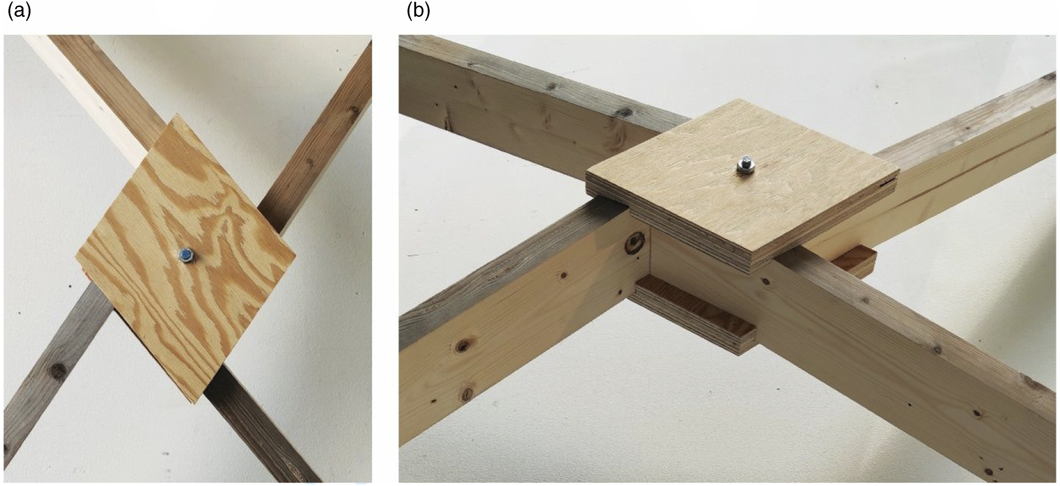
Structural model and analysis
Finite element method (FEM) was employed to predict the RF fan structural behaviour using two model instances: 1) 3D tetrahedral elements of one RF fan with four nexors and the connection geometry, using ANSYS software and 2) 3D linear bar elements for the overall structure, with fictitious elements to conceive the connections, using Karamba Grasshopper-Rhinoceros plugin. The role of the first model is to validate the fictitious element used in the second one, which was used to investigate overall architectural shapes.
The use of each software was essential since ANSYS is not integrated in the parametric modelling process used and it requires too much computational processing to analyse a whole structure with solid modelling. On the other hand, Karamba is integrated in Grasshopper and, because of that, it was incorporated in the RF generative algorithm. However, its limitation is the impossibility to analyse 3D solid or volumetric geometries, such as the one from the clamp connection.
Materials used and respective mechanical properties.

In order to find representative values of spring constant for the fictitious elements on the bar elements model, a fitting process was done by comparing the fictitious elements behaviour with the results of the solid model of the connection. For this, a load of 2.0 KN (200 Kgf) was applied transversely on the RF fan window to verify the displacements and maximum stress results. This process considered the maximum tension in bars, the vertical displacement of the fan window to fit the fictitious elements spring constants. Also, the shear stress level and distribution in the clamp connection geometry was evaluated to verify the clam connection suitability.
The solid FEM evaluation used elasto-plastic material properties for the nexors and the clamp connection. Figure 6 shows the timber stress–strain diagrams, taking into account the lowest axial strength as the yield limit and the highest one as the ultimate stress. The strain equivalence at yield stress was obtained from de Young Modulus and at the ultimate stress was based on a reference value for timber. Elasto-plastic strain–stress plot of C24 timber bars and the plywood connections. Source: made by the authors, 2021.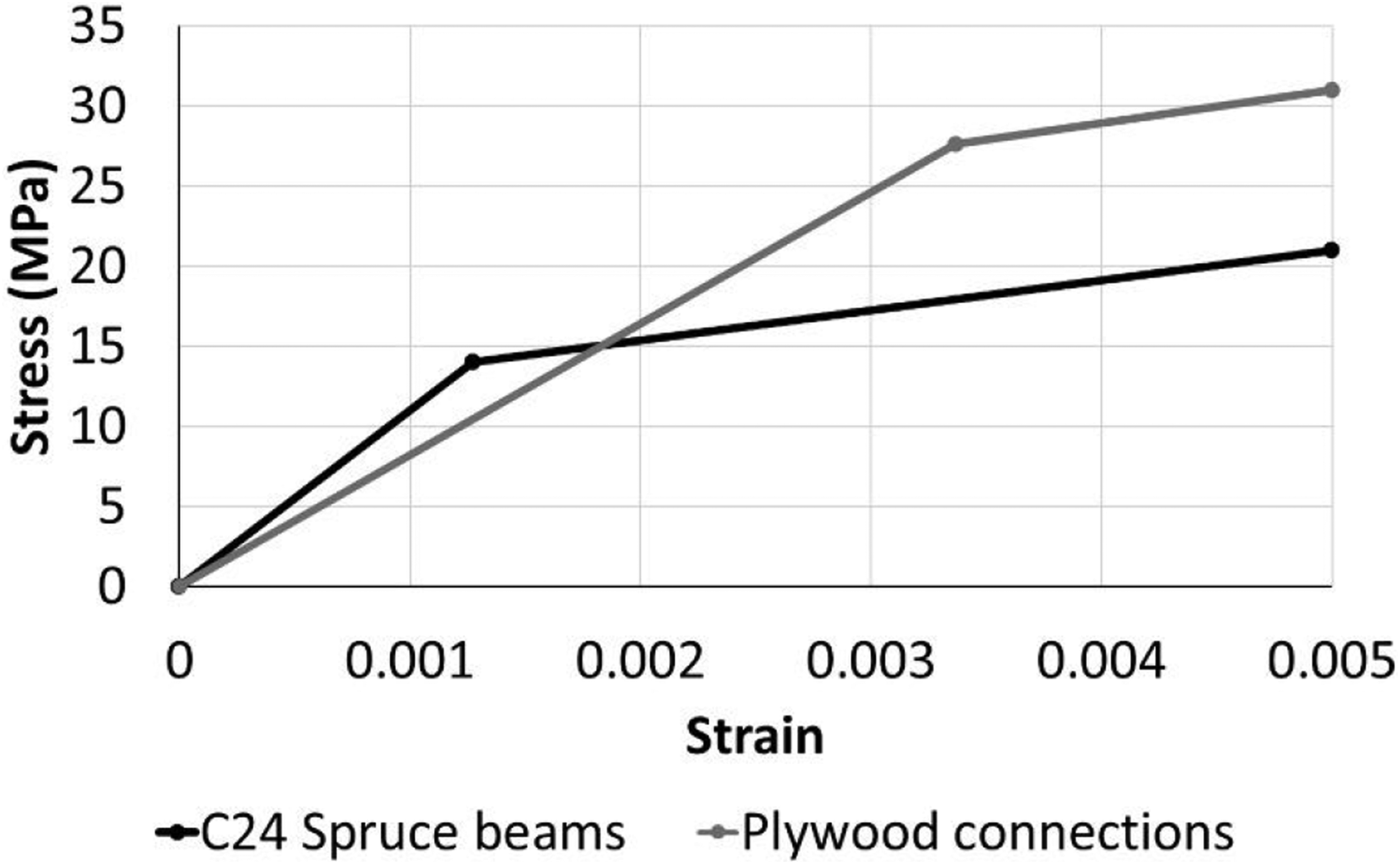
For the solid FEM, a polyhedric mesh was generated using a 10-node quadratic structural finite element to discretize the geometry, with approximately 5 mm edge size and a total of 1,568,796 nodes, which corresponded to 7,706,388 degrees of freedom. Mesh refinements were made at the edges and regions of elements contact, since these could be the areas of stress concentration. The generated mesh considered frictionless contact capabilities between the nexors, the clamp connection and the steel pin, modelled by contact elements. The isolated end of the nexors was supported at their bottom edge (Figure 7). The polyhedric mesh was made automatically by Ansys, using as inputs the geometric model and information regarding the mesh refinement areas. Geometric model for 3D solid analysis of the RF fan with the clamp connection. Images zoom in the bottom half of the connection to show the mesh refinement. Source: the authors, 2021.
The linear bar elements FEM evaluation used elastic properties, with the same timber Young Modulus constant, both for the fictitious element spring values and for the overall structure simulation. The fan geometry (Figure 8), used in the investigation process, was generated with four longer lines (represented in blue) imbued with the nexors’ material properties and other six shorter lines (represented in red) as the fictitious elements that corresponded to the connection geometry. These bar nexor elements were subdivided in several segments to improve the finite element accuracy, whereas the fictitious elements were modelled as springs, considering all six degrees of freedom: three translations and three rotations constants. These stiffness values were defined by a numerical fitting process accordingly the solid fan model results of maximum principal stress and displacements results. Geometric model for 2D linear analysis of the RF fan. Blue elements are the nexors and the red ones are the fictitious elements that correspond to the connection. Source: the authors, 2021.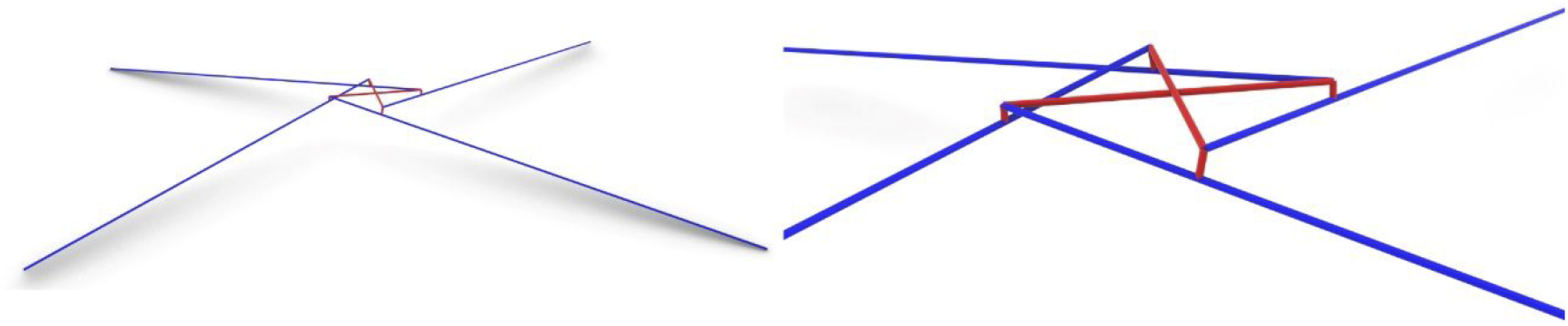
The calibrated fictitious elements constants based on the 3D solid FEM allowed overall structural geometries (configurations A–D) to be simulated in the parametric bar elements FEM (Figure 9). This way, it was possible to evaluate and verify the bars strength, buckling factor and displacements on Karamba. A python script was implemented for the strength verification, based on the Brazilian timber structural design standards.
17
It was a set of rules used to process the bending and torsional moments, as well as the normal and shear forces gathered on Karamba. The structural suitability was measured by normalized design ratios for normal stress (from bending moment and normal forces), shear stress (from to torsional moment and shear forces), displacement and buckling. These ratios ranged from 0% to 100%, whose calculation was the relation established between the simulated performance and their respective imposed limits. One of the calculation engines on Karamba is the buckling, providing the buckling load susceptibility value of the structure, which the inverse is an index that varies between 0 and 1, meaning that over 1, the structure buckles. This structural analysis framework provides a design assurance of the structural suitability of the proposed RF overall geometry investigations. Configurations A–D of the structural of a bar model for structural analysis using Karamba. Blue elements are the nexors and the red ones are the fictitious elements that correspond to the connection. Source: the authors, 2021.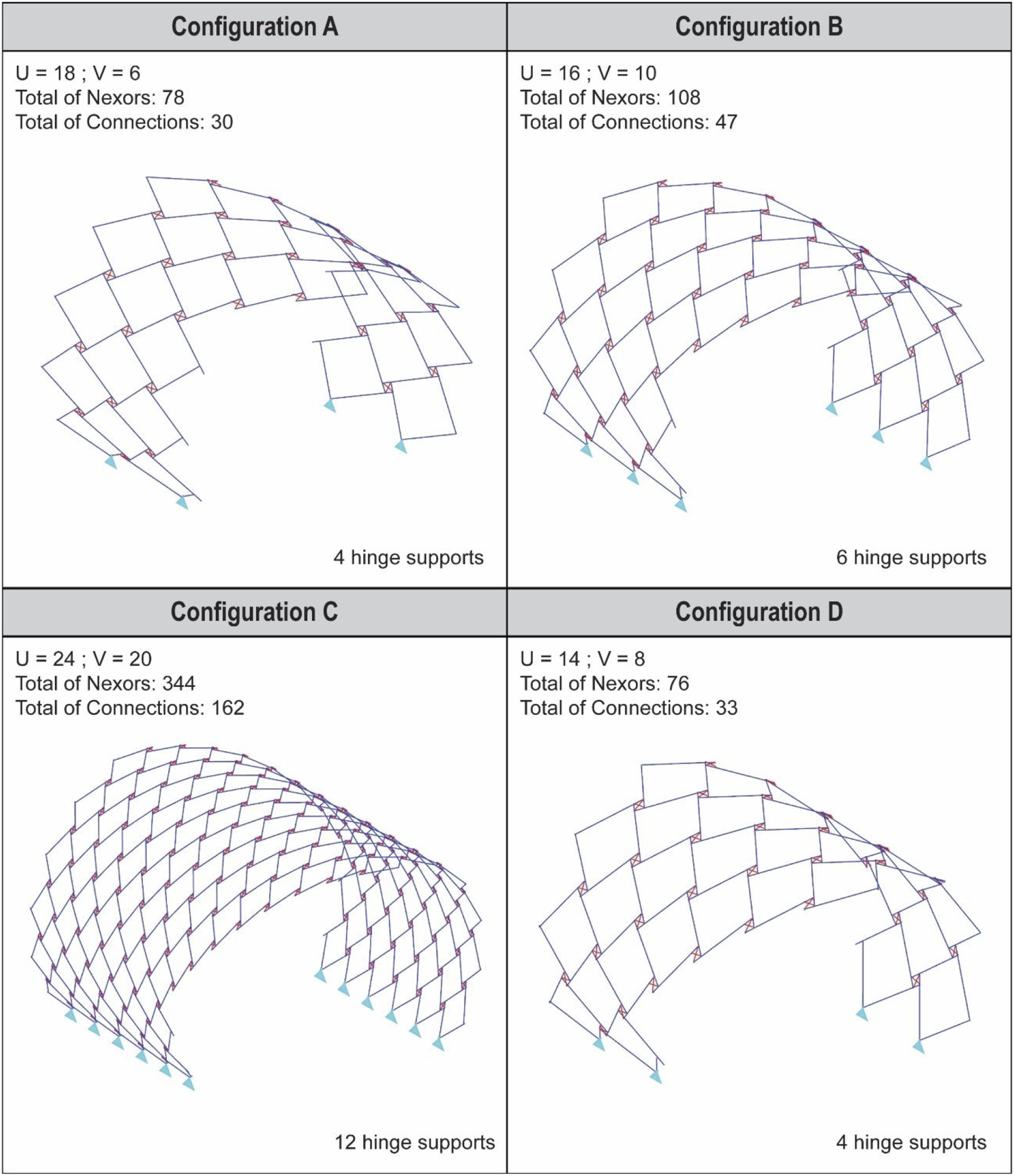
Findings and results
The use of algorithmic parametric modelling and prototyping allowed fast comparative and adaptive processes in a variety of RF configurations, generating a framework that probably would not be achieved by other design methods. The possibility of prototyping different connections and the assembly of a full-scale pavilion led to some interesting results, regarding the global and local geometries, structural behaviour, fabrication and assembly process, which are explained below.
RF fan and clamp connection structural results
The 3D solid FEM on Ansys exhibited the maximum displacement at the RF fan window of 0.080687 mm and around −4.51 MPa (compression) and 4.42 MPa (tensile) principal normal stresses at the flexural region on fan bars under the transversal load applied. These values were then used to fit the fictitious elements constants for the bar model. The maximum displacement at the equivalent region in this model was 0.076712 mm and −7.19 MPa (compression) and 4.13 MPa (tension) of principal normal stresses, which represents a variation of −4.9%, + 59.4% and + 6.5% against the solid model results, respectively. These results exhibit a very good fitting in displacement between both models and an acceptable fitting in maximum principal stress results.
The general behaviour of the RF fan from both virtual structural models is presented in Figure 10. Above are the results from the solid model, presenting the displacements (left) and the Von Mises stress intensity (right). They show the characteristic structural behaviour of flexure in the fan and rotation by the lateral flexure on the nexors. The maximum displacement occurs on the fan window region, oblique flexure appears on the nexors near to the connection and stress concentrations at the contact points between them. Below are the results from the linear bar model with fictitious elements, exhibiting the displacements (left) and principal stresses (right). By comparing this model with the solid one, it is visually noticeable that the structural deformation behaviour is very similar, which suggests a good equivalency of the use of fictitious elements to represent the connection. Above images show the Ansys solid FEM, showing displacement (left) and von Mises stress (right) results. Below is the 2D fictitious bars model from Karamba, exhibiting displacement (left) and stress (right) results. Source: the authors, 2021.
The fitting process related to the spring constants in the 2D bar elements model resulted in very high values, between 1.0 E+05 KN/m and 1.0 E+27 KN/rad for translation and rotation, respectively. Thus, these numbers could be admitted as infinite-like values for the overall structural modelling. The team also studied the clamp connection 3D solid FEM results. The higher stress values were for shear stresses, as it can be seen at Figure 11, showing concentrations at the pin contact regions and the edges contacts with the bars. Ansys 3 d clamp connection structural simulation shear stresses results. Source: the authors, 2021.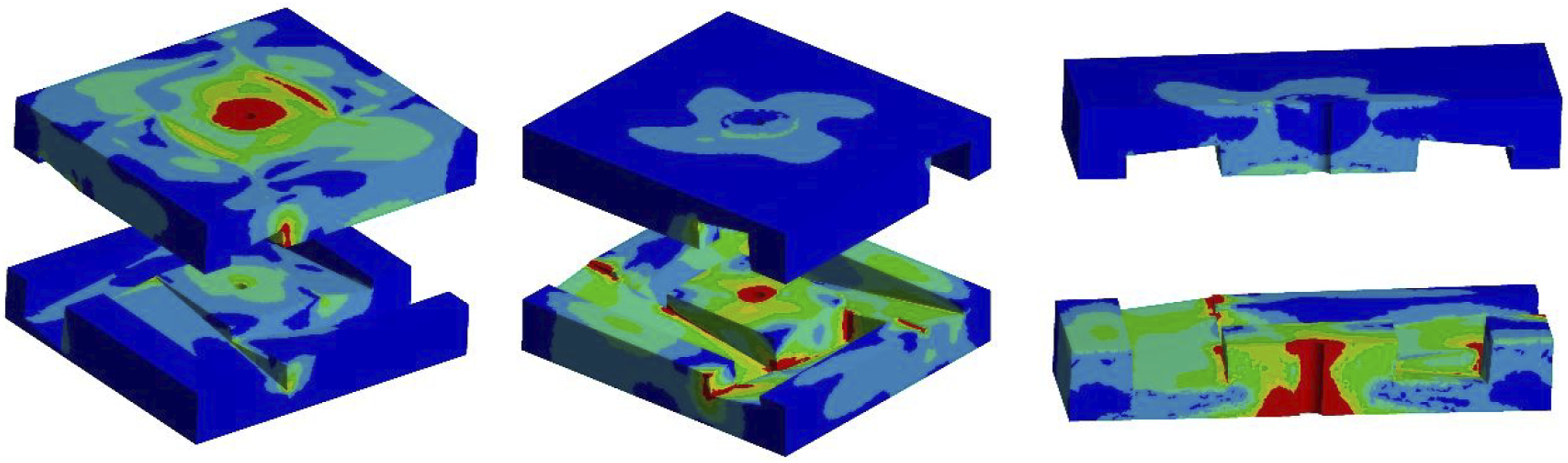
The regions in red showed stress values over the material shear strength, but the other colour regions are below the material shear strength for the load considered. This can be an approximated value of the real behaviour, suggesting that at the pin contact the clamp connection would develop plasticity strains easily for this intensity of 200 Kgf transversal load applied on the fan window. It is worth mentioning that these results show that shear stresses, the minor strength of timber, occur with higher values on the clamp connection and not in the nexors bars. Still, in the clamp connection the higher values of shear stress occur concentrated especially around the pin and it might provide some residual strength after material plasticization at these regions of stress concentrations.
The friction between the nexors bars and the clamp connection was not an issue on the structural behaviour in regard to this kind of loading, showing more flexure on nexor bars and shear on the clamp connection. It is expected that for larger spans the clamp connection made in timber could provide insufficient shear strength, including the intensity of cladding weight or wind loading. However, this can be mitigated by using other materials, with higher shear strength for the clamp connection, and/or by detailing and implementing new mechanisms on it.
Overall RF structure results and design performance
The acknowledgement of influence between geometry and structural performance led some explorations about the RF derivations from the vault used to build the pavilion. Different geometries were tested in Karamba using the bars elements model and submitted to self-weight only, in order to verify the geometry feasibility and if the dimensions of elements were structurally adequate. The comparative values presented in Figure 12 are related to the maximum stresses and displacement of each structure, as well as the design ratio for shear and normal forces. With that, it was also of interest which configuration would combine the performance with aesthetic appeal. Configurations A–D results from the structural simulation performed using Karamba. It is presented the design ratios obtained from configurations A–D. Source: the authors, 2021.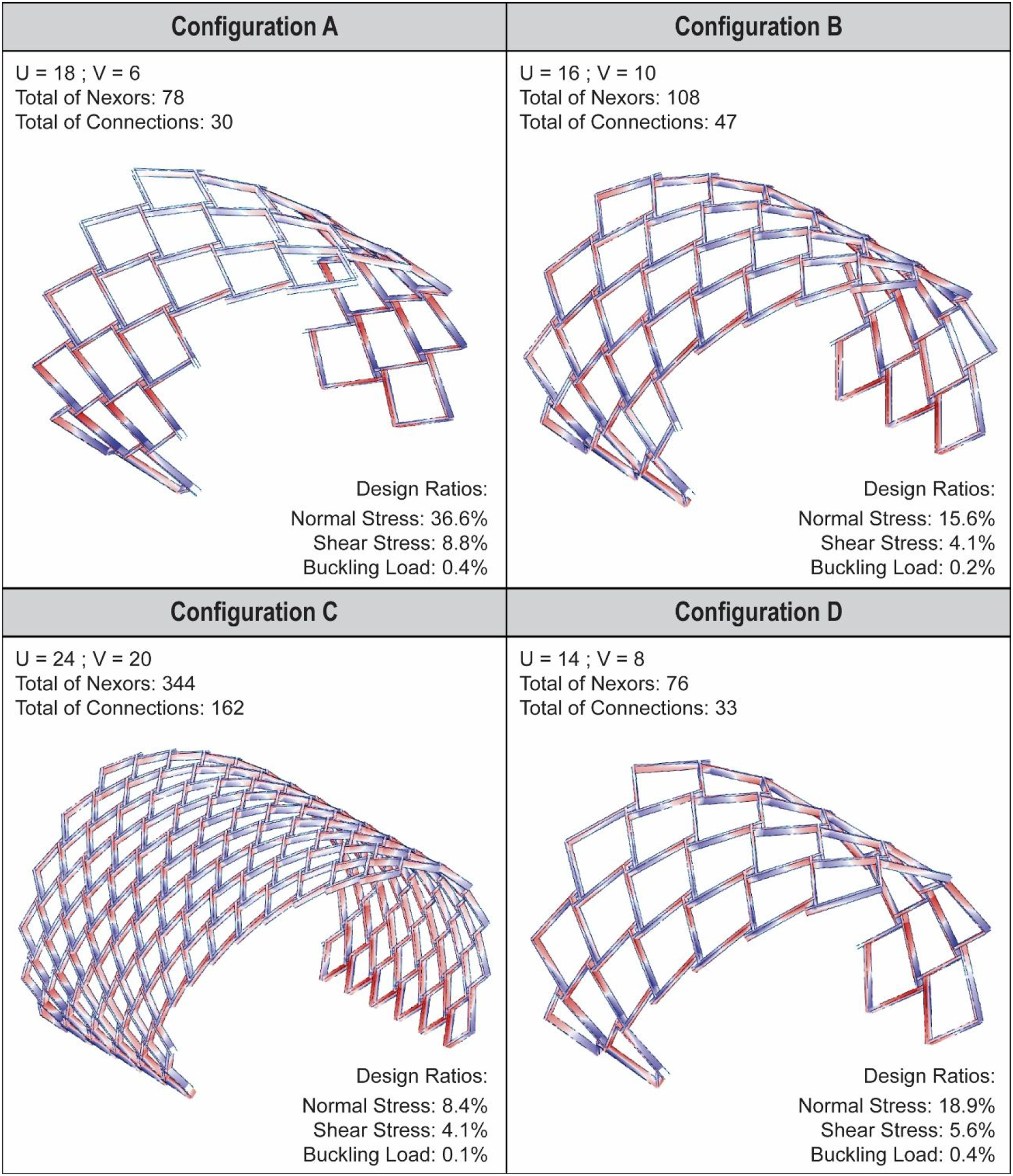
Once the result above was related to the overall structure response in this shape, an equivalent point load, normal to shape surface and acting on RF windows, was applied until it reached the same maximum displacement resulting from self-weight loading in order to evaluate the load level in fans. For this case, this equivalence was achieved with an equivalent point load on fans of 2.5 Kgf, a value well below the tested limit of 200.0 Kgf related in session 5.1. This approach can be a way to evaluate the level of force on the clamp connection in further investigations.
Proof of concept
The construction of a pavilion as a proof of concept was intended to verify multiple aspects: 1) the use of waste wood as an agent in design, 2) the algorithm functionality, 3) the production of connections and nexors, 4) the physical behaviour of the structures in a full-scale structure and 5) the assembly and disassembly processes. Due to the number of variables, the design needed some clearly set of boundary conditions. They were defined as 1) the size of the pavilion should not be too big due to the limitation of people for assembly and disassembly it, 2) the geometry should not be too complex, since at the same time, it would be the first real scale structure generated by the algorithm, built using a new type of connection and the reclaimed material, 3) the amount of available material should be taken in account and 4) the connections should be geometrically the same, since they would be hand-produced.
To attend these requirements, a vault geometry was defined as the input surface for the algorithm. The subdivision value for U and V influences the size of the connection element in a very specific way, which also depends on the curvature level of the inputted surface. In a simple or complex curved surface, the following rule is always applied: the greater the number of subdivisions, the greater is the granularity and the rendering of the original curvature. Since the curvature transference is done by the connections’ geometry, their size is very dependent on the granularity. The rule applied here follows as: the greater granularity requires thinner plates to transfer the curvature between nexors. Overall, there is a complex balance between the number and the size of the connections, which can be explored in a number of aesthetic and structural possibilities. For instance, if the subdivision in a vault geometry is increased in one direction, the required geometrical thickness of each half of the connection is lessened by a certain amount (Figure 9). Inevitably, the total number of connections is increased at the same time.
Figure 13: 3D connections in a perspective side view, exemplifying the thickness variation depending on the angular relation established between nexors. Measures in cm. Source: the authors, 2021. 3D connections in a perspective side view, exemplifying the thickness variation depending on the angular relation established between nexors. Measures in cm. Source: the authors, 2021.
In order to find an interesting balance between the number and the size of connections and nexors, the values of the controlling parameters were continuously changed. Each iteration converged closer to the final and accepted geometrical configuration. In addition to that, nexors and connections were removed iteratively, which resulted in different structural configurations. Then, these were combined with Karamba structural evaluations, in order to establish which derivation had the best structural performance. Through this process, which is presented in Figure 14, an aesthetically appealing geometry was defined, at the same time that it was a structurally efficient pavilion. Design workflow of the proof-of-concept pavilion. Source: the authors, 2021.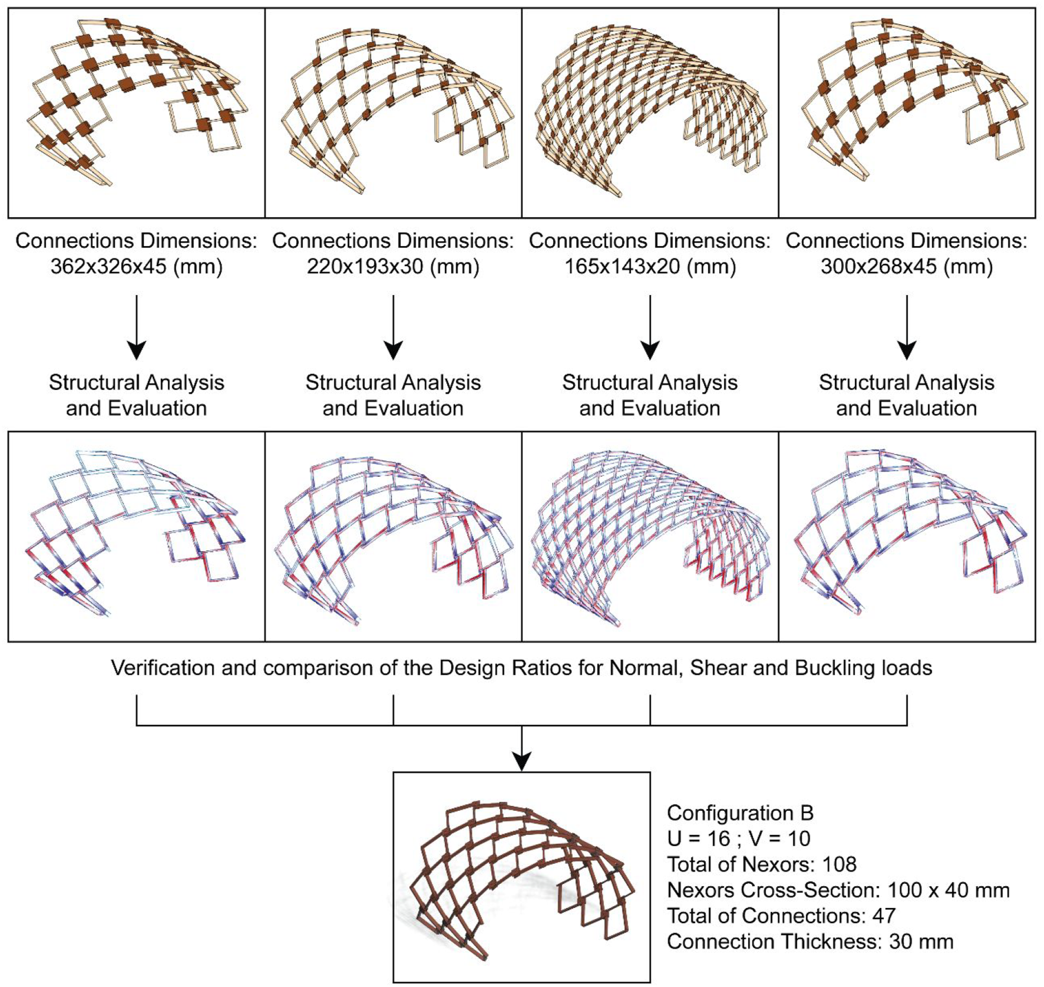
With the virtual geometry defined and structurally evaluated, the next step was the fabrication of all elements. Since different production methods were required for each element, they were held on two fronts: one related to the nexors and the other to the connections. A total of 47 connections and 108 nexors were used in this pavilion.
The nexors were made of C24 timber (spruce) with approximately 0.8 m long. They were obtained from 4.8 m long columns of a disassembled pavilion, found in container bins for waste disposal. The wood was exposed to wet weather (from Copenhagen) for some months and there were screws and holes in the pieces. In order to fabricate the nexors, the wood was dried outdoors, all the metal elements were removed and the dirt was cleaned. In this way, the wood could be reprocessed and reshaped, using widely available equipment.
The clamp connections were also made using waste material. The team used a number of high quality 15 mm sheets of plywood in different sizes, previously used as interior shop shelving. To achieve the necessary thickness (30 mm) for the connections, two sheets were glued together, and then, to obtain the desired diamond shape, they were cut using a saw table. With all 94 halves cut, the next step was to mill the grooves with the correct angles and dimensions to fit the nexors in.
The milling process was done using a hand router combined with four different templates, two for each half of the connection. This was possible since all the connections were geometrically the same, with two different groove shapes in each half. This means that the templates could be reused for all the connections, and, at the same time, one template was used for two grooves. It was just necessary to rotate the template 180°. The templates were 3D-printed in polylactic acid (PLA), and their geometry was the key to allow the correct and precise milling angles and dimensions. The diagram (Figure 15(a)) shows how the templates were used to produce the bottom part of the connections, and Figure 15(b) shows how the hand router was used. The same logic was applied for the top halves. Although in the present research, the connecting parts were milled with the use of a 3D-printed template and a manual router, due to the circumstances under which the work was developed, they could have been milled automatically in a 4- or 5-axes CNC router, especially if the structure required unique connections. (a) Diagram of how the template was used to produce the connection’s grooves and (b) how the hand router was used in with the templates. Source: the authors, 2021.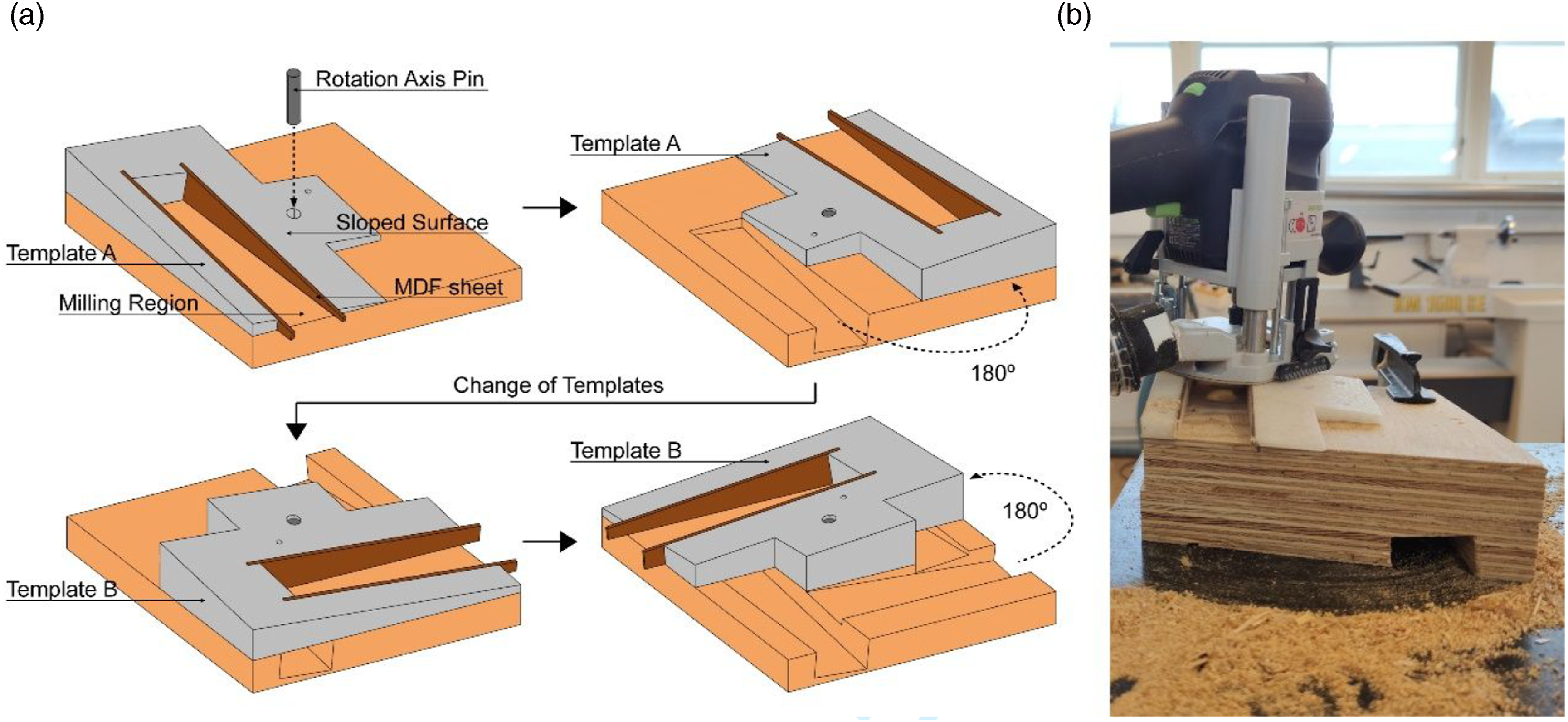
These templates were designed under six basic principles: The overall geometry should be the negative of the groove in the connections. The bottom was a flat surface that would face the plywood. The top was an angular and sloped surface that would act as support to the hand router. The inner faces were angular and would work as a guide for the router bit; since PLA is a fragile material, the hand router could destroy them. To solve this, a removable and sacrificial 3.5 mm MDF part was slipped in the inner walls of the templates, in which the router bit would lean on. The outer faces were planar and their geometry could guide the template positioning. A central hole and a metal pin were used for positioning and rotating the template.
As for the assembly process, an initial test was held by putting together only five fans. Its objective was to have insights of the best approach to assembly the whole structure later on. The best strategy found was an incremental method; fixing the fans in rows, from one side of the structure to the other. When a row was completed, the structure had to be lifted in order to assemble the next one and so on.
The connections played an important role to make this method feasible. With the first row assembled, each new fan that would be assembled was composed by two nexors that were already fixed to a connection from the previous row and another two that were completely free. To assemble the fan, some freedom of movement was necessary. The bottom half of the connections worked as a guide, fixing the two nexors that were already part of the structure in the correct position (Figure 16(a)). The top half was then screwed, but leaving gaps for movement. This way, the other two nexors that were free could slide in the connection (Figure 16(b)). When all four were in the correct groove positions, the screw was tightened until no gap could be noted (Figure 16(c)). It was exactly this freedom/tightening relation that made the assembly process viable. (a) Bottom part of the connection positioned under the two already assembled nexors; (b) the top half is attached and two other nexors are fixed, using the connection as a guide; and (c) the connection is tightened and the nexors are fixed in place. Source: the authors, 2021.
The pavilion stood for 1 week in an open space (Figure 17) before it was disassembled. In the meanwhile, it was exposed to different weather conditions, especially rain. Assembled proof of concept pavilion. Source: the authors, 2021.
Discussions and future work
This paper presented the development of a new connection type for RFs. Its main advantages are the ease and speed of assembly, since only one screw is used for fixing a whole fan, something quite unusual in this type of structure. The strategies to achieve this solution involved the study and combination of other existing connections and the principle of filling the fan void, as a way to obtain better control, give greater rigidity to the angles of the nexors and allow greater tolerance in the eccentricity. In addition, the development involved parametric and algorithmic modelling, structural simulations, prototyping of physical models and assembly tests.
The study had some limitations related to the time frame and working space restrictions as stated previously. Also, the algorithmic model developed was restricted to a specific type of RF composition (with four nexors for each fan). This type of connection would not work in configurations in which all the elements are under pure tension, although this might be very rare, due to the geometrical principles of RFs. Future studies should address other types of RF fan geometries, the use of other materials, mass customization of nexors’ cross sections and connections, alternative assembly methods and possible cladding systems for this type of structure.
Despite that, the team believes that the project can contribute to the continuously developing field of RF, especially with the novel approach to deal with the geometrical complexity, enabling simple and easy construction and elegant visual expression. Beyond the specific solution presented here, the methodological path described in this paper can be applied in the development of new types of connections, especially with the use of parametric and algorithmic design and digital fabrication tools. It is worth noting that the use of the algorithmic model allowed high adaptability to freeform and fast testing with many geometries, uncovering unpredictable possibilities.
Footnotes
Declaration of conflicting interests
The author(s) declared no potential conflicts of interest with respect to the research, authorship, and/or publication of this article.
Funding
The author(s) disclosed receipt of the following financial support for the research, authorship, and/or publication of this article: The authors gratefully acknowledge the grant #2019/22605-8 of the São Paulo Research Foundation (FAPESP). Also, the authors thank the National Council for Scientific and Technological Development (CNPq) from Brazil, in providing support to this research by the Universal MCTI/CNPq N°01/2016 call, project #400437/2016-3.
