



Abstract
This paper argues that computational design coupled with additive manufacturing (AM) holds the potential to transform precast façade design and construction. Computational design empowers the creation of intricate façade forms, while AM facilitates their fabrication. In two distinct ways, AM is poised to disrupt precast construction: firstly, through 3D printed formworks (3DPF), and secondly, by employing AM to produce the positive reference pieces for mold making. This paper’s focus lies on the latter method, particularly within an educational context. It reviews a novel pedagogical approach that was implemented in a design studio at Illinois School of Architecture. This pedagogy bridges the past and the future by reinterpreting historical projects and reimagining them using today’s advanced technologies. The incorporation of historic precedents into education implies a practical approach to design thinking, especially in mold design and fabrication. The outcomes highlight the intersection of established construction knowledge with emerging digital fabrication techniques.
Introduction
Kiel Moe, in his article “Building Agnotology,” describes agnotology as a form of knowledge production that directs attention to what remains unknown and why. Agnotology considers how ignorance develops, gains momentum, and in the case of pedagogy, identifies topics left unlearned. Moe further argues that although a minority of faculty may acknowledge ‘building’ as a legitimate category of knowledge production, it often revolves around composition and assembly of architectural objects. This narrow pedagogical approach limits our understanding of building as a dynamic process. 1 In fact, the networks of people, ideas, and materials directed through the process of building are far more complex, and potentially impactful, than the design of buildings. 2 While current architectural education emphasizes high-performance and sustainable building enclosure design or complex assembly of building elements, precast building enclosures raise unfamiliarity regarding the interplay between module design, mold design, and labor. This paper argues that these aspects remain inadequately explored, if considered at all, in architectural education. There are multiple steps for casting a malleable material: creating a positive reference part, conceiving the formwork as the negative of the desired part, then pouring the liquid concrete, and finally, demolding the hardened part. The pedagogy presented here brings to the forefront the overlooked aspects of designing and fabricating precast façade elements, including the intricate design of modules, mold conception, and the implicit labor underlying the entire process.
This article begins by examining the past, present, and future prospects of architectural precast in facades. It then delves into the pedagogical approach implemented in a studio setting offered at the Illinois School of Architecture. Afterwards, the paper exemplifies three historic precast façade precedents by explaining their design and fabrication techniques. These selected precedents feature sculptural, complex, and custom-designed modules. Each precedent undergoes a historical review, followed by an analysis of the students’ approach to its recreation and fabrication. The discussion section discusses the pedagogy, incorporating students’ feedback on the project alongside the instructor’s observations on additional precedents. The results section examines the results, establishing connections between students’ initial skill levels, and the successful delivery of their projects. Finally, the Conclusion provides a summary of the outcomes and reflections on the pedagogical approach.
Past, present, and prospects of precast
During the 1950s, the United States witnessed the development of curtain wall systems featuring sleek glass facades. Architects, engineers, manufacturers, and developers were driven by the goal of creating an economically efficient system that projected a progressive image. 3 The growing prevalence of curtain wall facades raised concerns among critics who expressed unease about the potential alienation caused by the repetitive panes of these structures. In 1954, Saul Steinberg, a renowned artist known for his New Yorker cartoons, humorously transformed an actual piece of graph paper into a towering curtain wall structure, mocking the curtain wall’s impact on the traditional urban fabric. This artistic irony led to the term “graph paper architecture,” coined to describe these buildings, suggesting that anyone capable of creating a grid could design such structures. 3 Consequently, concrete, a material characterized by its plasticity that lends itself to expressiveness, was considered as a viable alternative to the glossy, reflective surfaces of the curtain wall. 3
The use of precast modules in building envelopes persists in today’s architecture, employing concrete or alternative materials. One notable distinction between the contemporary cases and the concrete modules of the 1960s era lies in the design variation among façade modules. When examining precast envelope systems constructed in the 1950s, variability in the design of envelope modules was limited. This limitation stemmed from the associated cost and labor of molds, necessitating their repeated use. In contrast, today, the use of computational and parametric design tools has allowed a multitude of designers to create non-identical elements for facades. 4 However, variable façade systems remain predominantly present in a select set of projects designed by star architects who typically undertake projects with higher budgets. From a different perspective, many of the precast elements of the 1960s era feature complex and sophisticated forms designed by sculptors and renowned designers, aiming to manifest concrete’s potential. Currently, the creation of complex precast forms is not widespread due to the industry’s emphasize on employing more streamlined and cost-effective production methods, coupled with budget constraints in most projects. Only a small percentage of the projects have the financial capacity to realize geometrically complex precast façade systems. Examples include the Broad Museum by Diller Scofidio + Renfro Studio, 5 Prosolve 370e by elegant embellishments Ltd, 6 and Morphosis Team’s design for Kolon Industries Incorporation in Seoul. 7
Another distinction between past and contemporary precast facades lies in the fabrication methods of concrete elements. Advanced digital fabrication methods have emerged, often registering marks on the concrete elements. For instance, a smooth curved surface in digitally fabricated concrete may indicate the use of molding method, while observing deposited parallel and continuous layers of concrete suggests using the liquid deposition modeling (LDM) method. Emerging digital fabrication methods have the potential to be widely adopted by industry, expanding the realization of geometrically complex forms while facilitating efficient production of these geometries.
Contemplating the prospects of precast façade elements, there is awareness regarding the negative environmental impact of concrete. 8 Therefore, material optimized concrete design and efficient construction methods are major research focus in the field. The key fabrication technique for transforming concrete construction is additive manufacturing (AM). Additive manufacturing technology can revolutionize two aspects of traditional precast construction: Either the formwork can be 3D printed, referred to as 3D printed formworks (3DPF), or the reference part used in mold making can be 3D printed.
Reviewing the literature on 3DPF, it has mostly been utilized to showcase the potential of bespoke fabrication. Examples include melting 3D printed PolyLactic Acid (PLA) molds with a heat gun, 9 3D printing sandstone molds that remained in place, 10 or dissolving PolyVinyl Alcohol (PVA) formwork. More recently, with a shift towards exploring new design approaches and materials for repeatable use 3DPF, a range of new research projects has emerged.11–14 Although 3DPF is a leading method for creating complex geometries and controlling the surface quality of precast concrete, approaches involving sacrificed mold parts are incompatible with economies of scale, while the materiality and durability of reusable 3DPF molds require further investigations.
The second disruption by AM in precast involves 3D printing the initial positive part — also called the reference part — to be used in mold making. This approach is currently underrepresented in literature. This disruption is significant from three points of view: - First, as AM technologies continue to advance and become more prevalent, this method can promote the design of complex and optimized precast geometries due to the inherent efficiency of creating the reference piece. - Second, it can have an impact on the industry by facilitating the creation of geometries with embedded textures. Using the 3D printed reference piece with embedded textures can eliminate the need for patterned mold inserts such as formliners to create patterns on precast elements. - Third, this approach can impact education at architecture schools. There is a need to incorporate leading research studies on AM into classrooms to educate the future generation of designers and architects. Desktop 3D printers are state-of-the-art in many schools and can be utilized to educate architecture students on the future of precast industry. This paper showcases the potential of AM in teaching precast construction.
Pedagogy
The pedagogical approach entails an examination of historical precast facades, followed by the recreation of these precedents using today’s advanced technologies, namely computational aided design (CAD), and AM. This pedagogy serves not only to bridge the past and the future, but, more significantly, to establish a direct engagement with the fabrication reality surrounding the precedents in both eras. The utilization of historic precedents in education implies a focus on technical and tangible design thinking. Additionally, the pedagogy draws attention to the overlooked aspects of education in precast building enclosures, particularly regarding the design and fabrication of façade’s modules.
Focusing on design, upon evaluating historical precast facades, it is recognized that sculptors often collaborated with architects in designing the façade modules. Today, in the context of REVIT product libraries, designing complex geometries for facades poses a challenging task for architecture students. Conversely, if students are willing to tackle the challenge of designing sophisticated geometry, their initial attempt might very likely involve a Grasshoppered Voronoi pattern. One of the objectives of analyzing historical precast elements is to enable students to comprehend how having control over geometry at a micro level, coupled with a deep understanding of the geometric constructs such as lines, curves, and cross sections, can lead to the creation of complex yet sophisticated elements.
Focusing on fabrication and construction courses currently offered at the architectural schools, two main approaches are commonly found: abstract construction courses that require students to create detailed drawings of building assemblies, and Design-Build studios where students participate in physically assembling building components. While both approaches in solo or in some level of combination hold value, courses that emphasize creating wall section detail drawings or a participating in Design-Build studios often tend to be disconnected from design in its artistic form, where aesthetics and proportions of the geometry play a crucial role. This disconnection arises because creating construction drawings or engaging in the construction process consumes a significant amount of time for students, demanding the majority of course time to be dedicated to these tasks.
Analyzing historical precast facades for their design and fabrication followed by fabricating the elements using contemporary means, inherently limits the scope and the scale of the project. This limitation encourages students to focus on both design and fabrication. This middle-ground educational approach allows ‘design’ to maintain a balanced role alongside hands-on activity, rather than being diminished or eliminated altogether. Today, in the context of rapid prototyping where state-of-the art 3D printers are readily available to students, another objective of the studio was to demonstrate the potential of AM beyond model making. The pedagogy highlights the disruptive impact that these technologies can have on the building industry. This pedagogical method could serve as a precursor for introducing other innovative methods for creating precast elements, such as 3DPF.
A six-credit design studio, paired with a three-credit hour seminar, was offered at the Illinois School of Architecture of the University of Illinois at Urbana-Champaign, with access to Digital Technologies in Architecture (DiTA) Research Lab's 1 resources. The syllabus for both the studio and the seminar was developed in tandem. The studio incorporated design and fabrication activities, while the seminar aimed to enhance students’ understanding of the field’s state-of-the-art knowledge through in-class discussions on selected readings and guest lectures from academia, industry, and practice. Additionally, the seminar provided computational design lessons to develop students’ computational design skills.
The design studio comprised two projects. The first project, lasting 4 weeks, allowed students to delve into historical precast facades, focusing on studying their design and fabrication technologies. The second project, spanning 10 weeks, tasked students with exploring the application of AM in the design and fabrication of self-standing precast elements. This paper focuses on reviewing the first project.
Project one started with the presentation of a series of precast facades and self-standing sunscreens featuring sculptural, complex, and custom-designed modules to the students. They were asked with selecting a precedent, conducting research on it, and reproducing the forms in a computational design environment by interpreting the images and found drawings. Additionally, the students were introduced to AM and educated about the file-to-factory workflow for transforming computational forms into 3D printed objects. They were also trained on operating 3D printers. Once the students had fabricated the module’s geometry, they were introduced to rubber mold-making techniques, specifically OOMOO-25 silicon rubber compound by Smooth-On, referred to as rubber mold in the text. Students were guided to create a one or two-part rubber mold for casting multiple instances of the precast modules before assembling them into a facade or a self-standing screen. It is noteworthy that Hydraulic Expansion Cements (HEC), particularly Rockite, were used for casting instead of traditional concrete made up of coarse aggregate. Rockite only requires mixing with water and sets rapidly, allowing demolding within an hour of casting.
From another perspective, various precedents had different module sizes, ranging from modules that covered a floor-to-floor height, to modules similar in size to a brick. To ensure a consistent workload for students in terms of the time needed to 3D print the positive part and the amount of material needed for creating the rubber mold and casting, all students were instructed to 3D print their case study modules to fit into a 5” × 5” × 5” (12.75 × 12.75 × 12.75 cm) cube. They were directed to ensure that the longest dimension of the cube could fit within the aforementioned dimensions. This approach facilitated the creation of cohesion among the level of detail visible in the modules while requiring roughly the same amount of material for the students’ projects.
Upon completion of the project, the outcome was evaluated based on four criteria: - Analysis: Students conducted an analysis the geometry of the precast façade elements, assessing their repeatability and the reusability of the mold by evaluating the number of designed module types covering the façade and the number of required mold types. - Modeling: Students demonstrated their understanding of the complex geometries of the modules in the facades and acquired the skills to replicate them in a CAD environment. - Additive manufacturing: Students acquired the skill to utilize AM for creating the façade’s module geometry, which would then serve as a reference part in mold making. - Mold making and casting: Students demonstrated proficiency in executing the necessary steps for making precast concrete, particularly in designing a mold for complex geometry while considering undercuts and demolding direction after casting it. Furthermore, students exhibited an understanding of the effect of the fabrication method, namely AM on creating patterns and textures on the reference part and the final cast instance.
Three historic facades are selected to be exemplified in the following sections. These three case studies serve as significant examples of precast building envelopes. The first precedent, the American Cement Building, formerly the industry’s headquarters in Los Angeles, USA, was designed to showcase the strengths of precast. The second precedent, the IBM building in Honolulu, is another instance of a corporate building integrating precast elements into its façade, highlighting its distinctive form. The third precedent, the Welbeck Car Park in London, UK, represents car park as a civic movement where precast modules were utilized to cover the building. Each historic precedent is subsequently followed by reviewing the students’ approach to its analysis, modeling, and fabrication.
American Cement Building’s screen in Los Angeles
Some sculptors, such as Malcolm Leland, collaborated with architects to design modular volumetric elements for building facades. The American Cement Building in Los Angeles was designed by Daniel, Mann, Johnson, and Mendenhall (DMJM) in collaboration with Malcolm Leland (1961). The executives of the American Cement Corporation aimed to construct a new headquarters that would promote reinforced concrete as the building material of the future in dramatic fashion. The Corporate Office Buildings were converted into loft buildings in 2011. 15 Daniel, Mann, Johnson, and Mendenhall designed the 13-story building as a two-unit structure: a 4-story base for parking, ground floor shops, lobby, executive offices, and a 9-story tower 16 . Kiewit Construction won the construction contract through a design-build procedure deemed novel at the time. 16 “Some of the structural elements were poured in place using wooden forms; others were poured in place using plastic-faced wooden forms to produce a textured effect. Some of the individual members (X-members, garage grill elements, floor beams) were cast away from the site, hauled in, and hoisted into place”. 17 The precast concrete X-members are both dramatic and functional. The 11-foot (∼3.35 m) reinforced members take lateral forces on the north and south sides of the building. Therefore, no interior columns are above the fourth floor. The 450 X-members weigh 4500 pounds (∼2041 kg) each. 18 The corners of the elements allow them to hook onto the edge of the upper and lower slabs. The pre-installed rebars in the precast member appear to be in place to create a monolithic union through on-site concrete pouring once modules are placed.
The other module designed for the building was the sculptural precast screen enclosing the garage that provides ventilation, protection, and a rich surface texture that is harmonic with the X-member wall. 17 The 250 sculptured concrete garage grille members weigh 3000 pounds (1360 kg) each. 18 “The parking annex façade is non-load bearing” 6 (p. 55).
The student who reproduced the X-members used computational modeling (Figure 1-left) and 3D printing to create the module, with its geometric proportions being very close to that of the precedent. According to the fabrication report submitted by the student, their main challenge was designing, fabricating, and casting a mold. The student first made a two-part mold for casting the pieces. But since the rubber mold material and the activator were not thoroughly mixed, the rubber mold never cured. In addition, the student dismissed applying the mold release agent to the mold parts during production; thus, the two parts of the mold became homogeneous and never came apart. In the second attempt, the student designed a one-part mold (an open mold) and observed how eliminating the process of producing a one-part mold increases the production speed. After successfully making the mold (Figure 1-center), the student’s initial attempts to cast it all failed because of the module’s narrow legs, prone to breakage. In this stage, the student paid closer attention to various cement-to-water ratios. The 2:1 ratio created brittle elements, whereas the 4:1 ratio created successful intact cast pieces without using any reinforcement. In this phase, the student also gained a qualitative understanding of concrete mix design, where a higher cement portion in a mix makes the cast piece more brittle. In contrast, a higher water portion can slow down the solidification process. Finally, the student adhered the cast pieces together to create the standing façade (Figure 1-right). Step by step CAD drawing of the module (left); the rubber mold created by 3D printing the reference piece (center); the assembled cast pieces (right); drawing and work by Atousa Esmaeili.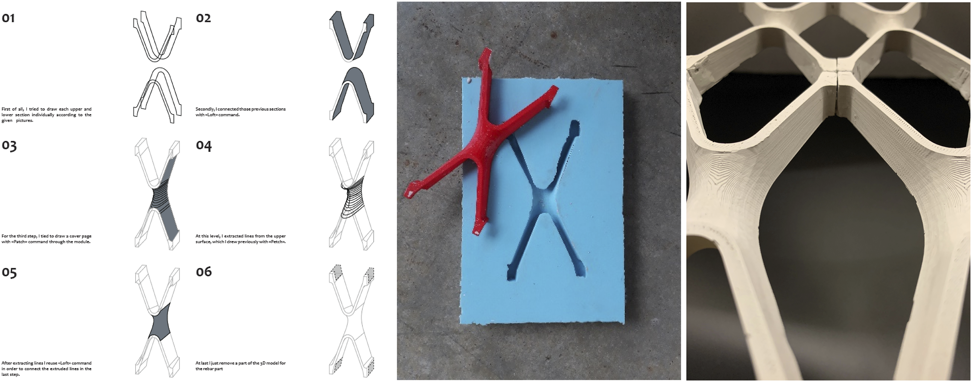
Upon completion of the project, the instructor realized that learning about precast joinery is crucial in this project. Although the geometric proportions of the module and assembly were a close replica of the reference case study, the method of construction and module attachment to the slabs was not reflected in the final assembled model. Even though the student modeled, and 3D printed the notches behind the X-member’s legs for connecting the module to the floor slabs, they filled it out with clay upon casting them to increase the strength of the cast piece. Therefore, they used glue to assemble the modules into a facade instead of creating an assembly that closely represents the construction method. Changing the modules’ scale in the model and increasing the duration of this project will allow students to dive deeper into the connection details and construction techniques of the precedents.
Another student worked on modeling and fabricating the precast module used in the garage grillage of the American Cement Building. The geometry of this module was complex and challenging for them to model computationally. According to the fabrication report submitted by the student, one of the lessons that they learned was how to analyze complex geometries and break them down into simple shapes or curves before modeling them. The student was successful in making a two-part mold following all the instructions. However, they experienced failure during the casting phase. They, too, oscillated between making a thick mix, not allowing concrete to move in the mold, and creating a runny mix resulting in fragile cast pieces. It was on the third attempt that they got the mix right. The student also observed the importance of applying pressure to mold pieces, so the mold does not leak. They also realized the importance of vibrating the molds for outing the air bubbles by shaking the mold after casting. Finally, the student used cement to connect the modules to one another. They had correctly understood that the modules are non-load bearing and are stacked before being bound between the lower and upper slabs of the building (Figure 2). Step by step CAD drawing of the module and the demolding direction of the designed part (left), trying multiple mix designs for casting the rubber mold (center); the assembled cast pieces into a facade (right); drawing and work by Bryant Nunez.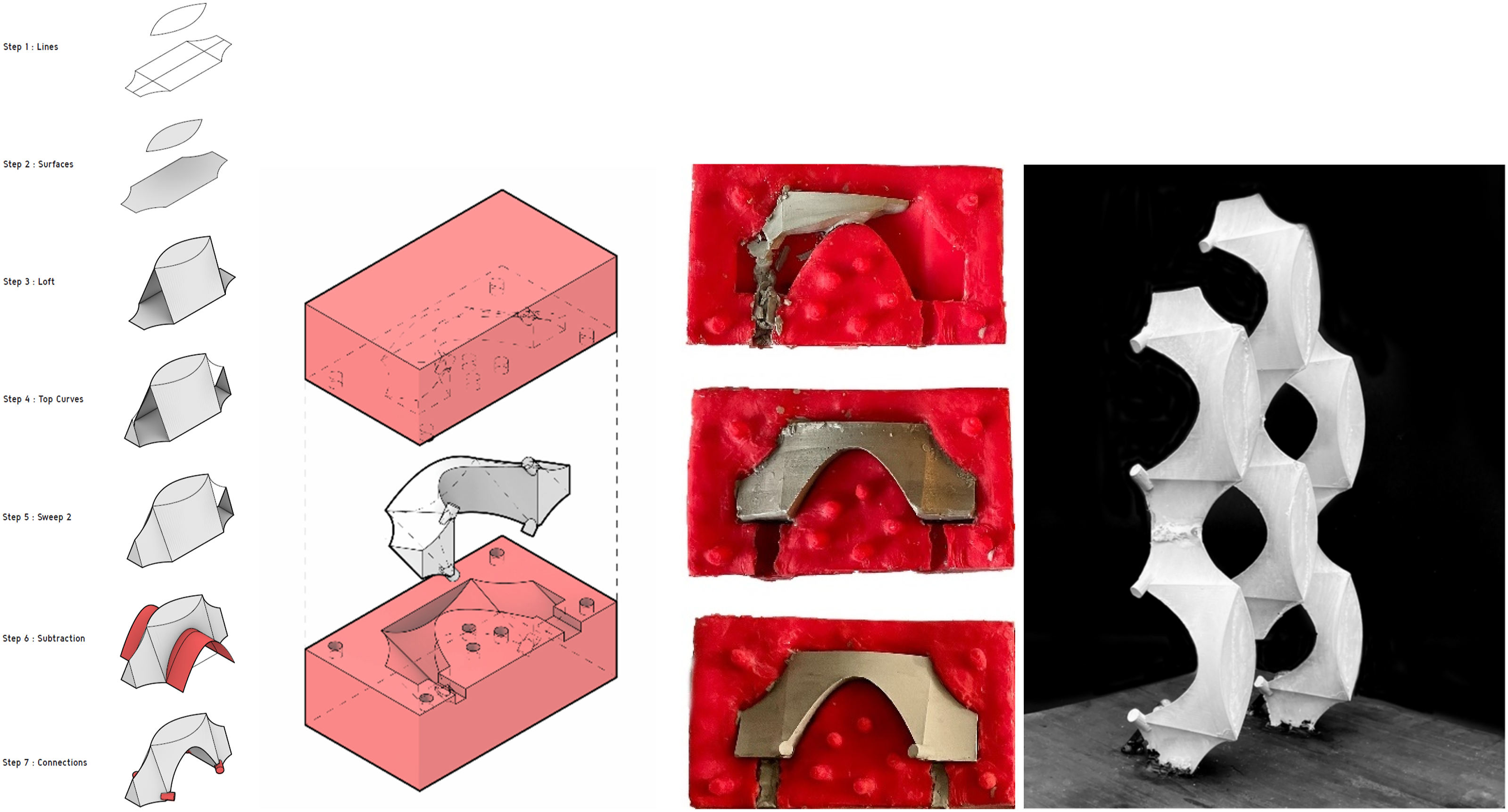
An important observation the student made was relating the three-step mold-making process to real-world precast concrete production, except that more advanced tools and reinforcement materials are used in the industry. This observation is crucial and demonstrates that making the small-scale mockup has engaged the student in fabricating a component and constructing an assembly which is beyond making an architectural model. In fact, the student understood the act of building.
IBM building in Honolulu
The IBM building, located in Honolulu, Hawaii, was designed by Vladimir Ossipoff and Associates Inc. and was built in 1962. The 6-story office building is framed with prestressed concrete joists and composite poured-in-place concrete slabs and beams. A honeycomb concrete brise soleil inspired by Polynesian culture intending to resemble the punch cards used in the computer industry wraps around the building. The decorative concrete grill comprises 1360 precast pieces surrounding the upper floors, providing an effective sunshade
19
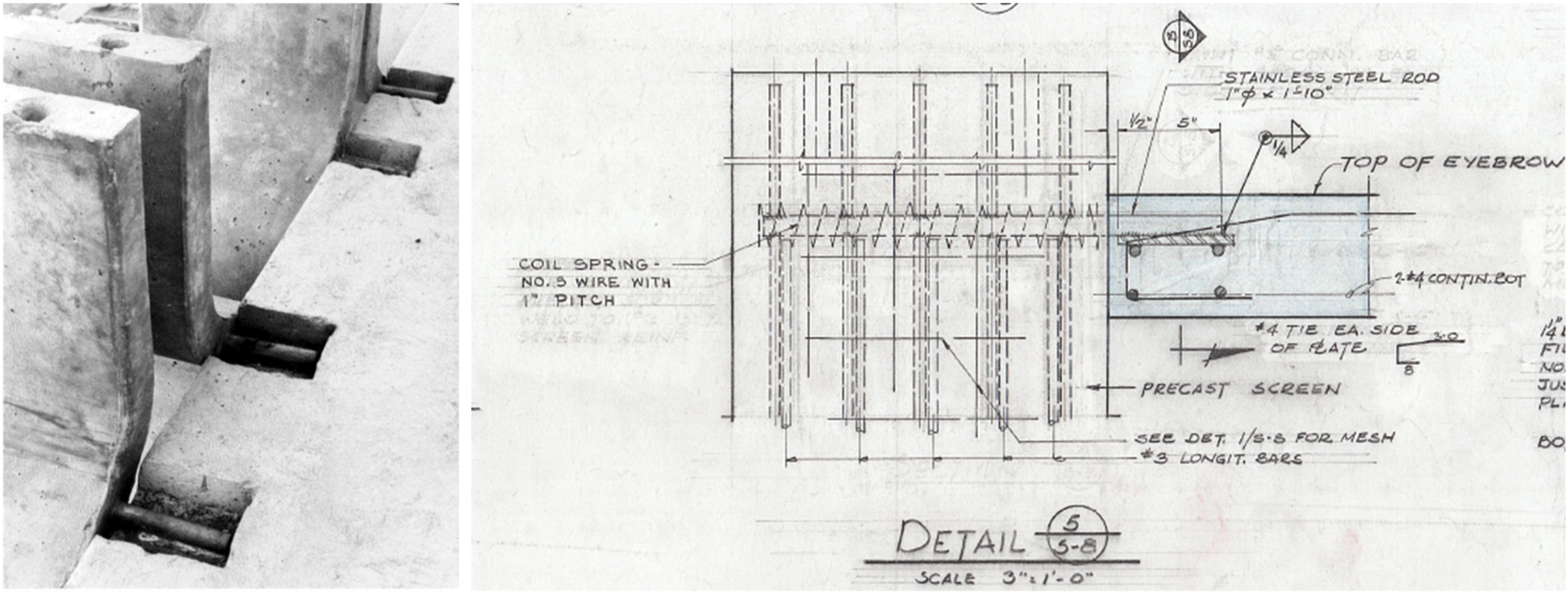
(Figure 3-left). By inspecting the construction images, each vertical row of the concrete grill consists of smaller precast sections before being attached to the slabs (Figure 3-right). For module-to-module connections, the top faces of the modules have insertion holes for incorporating rods that vertically connect the grill modules to each other. Figure 4-left shows the modules laid down on the construction site where the insertion holes are visible on the top surface of the module. Figure 4-right shows the construction detail drawing. According to construction documents, the insertion holes are 12’ 2” (∼35.56 cm) deep, and it is instructed to fill the ¼” (6.35 mm) holes in the lower part of the precast module with non-shrink grout just before positioning the upper module. For module-to-slab connections, there is an insert for passing stainless steel rods onto the side of the precast modules (Figure 5-left). Figure 5-right shows a construction drawing that instructs to fix the joint by inserting the steel rods into the concrete slabs. IBM building’s precast grill attached to floor slabs (left | image courtesy of Dr. Don Hibbard’s donation to the Haigo & Irene Shen Architecture Gallery, University of Hawaiʻi at Mānoa); IBM Building’s precast mosules laid on-site (right | image courtesy of Dr. Don Hibbard’s donation to the Haigo & Irene Shen Architecture Gallery, University of Hawaiʻi at Mānoa). Module-to-module connection: the precast module laid flat on site, showing two insertion holes for inserting rods (left | image courtesy of Dr. Don Hibbard’s donation to the Haigo & Irene Shen Architecture Gallery, University of Hawaiʻi at Mānoa); IBM Building, drawing of module-to module connections in elevation as seen in the façade (right | Image courtesy of the Ossipoff & Snyder Architects Collection, University of Hawaiʻi at Mānoa). Module-to-slab connections by inserting stainless steel rods into floor slabs (left | image courtesy of Dr. Don Hibbard’s donation to the Haigo & Irene Shen Architecture Gallery, University of Hawaiʻi at Mānoa); IBM Building, drawing (right | Image courtesy of the Ossipoff & Snyder Architects Collection, University of Hawaiʻi at Mānoa).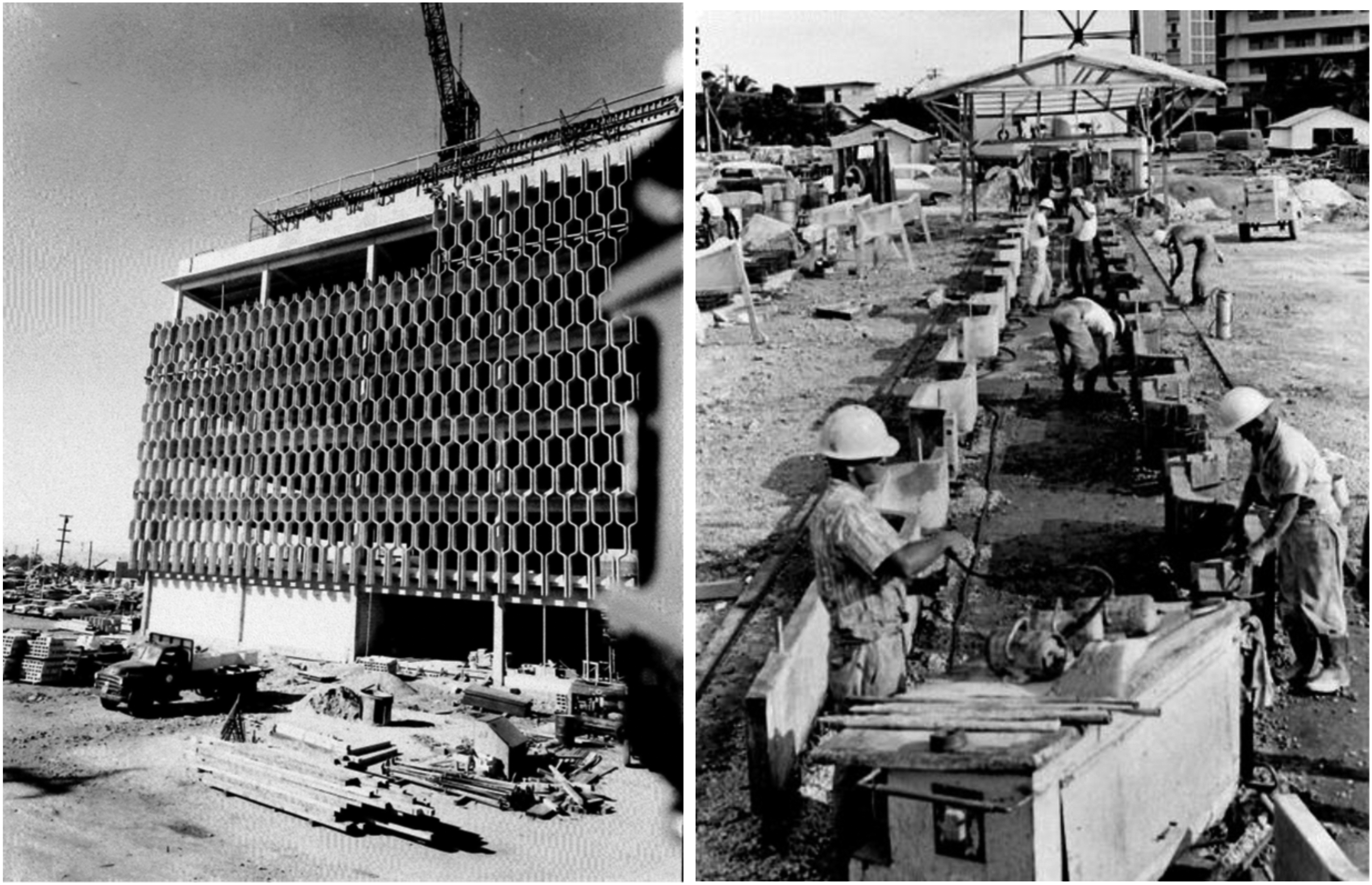

The student approached working on the project by modeling the smallest geometric module that was making up the honeycomb facade (Figure 6-left). They first modeled this smallest module in proportions larger than the actual module size and created a two-part mold. By casting the two-part module, they realized that using one half of the mold and using it as an open mold would not only create a module with the correct proportions but would make the casting and demolding process straightforward. The 3D printed piece used as the positive part for making the rubber mold and the open mold are shown in Figure 6-center. Afterward, the student used the open mold to cast the smallest module of the façade multiple times. They then glued the smaller pieces together using hot glue to make the grillage assembly before connecting them to the lower and upper floor slabs (Figure 6-right). CAD drawings of the student’s perception on the assembly of the smallest module (left); open rubber mold (center); assembled screen of the IBM building by cast pieces (right); drawing and work by Krishna Jayachandran.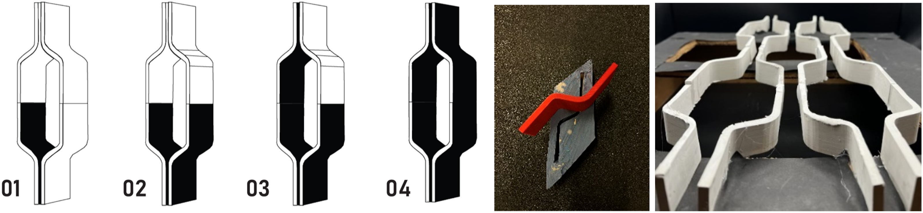
The student’s approach to analysis and fabrication is both similar to and different from Ossipoff’s design for the IBM facade. In Ossipoff’s design, there exists a base precast module (each containing six filleted edges), and then three of the precast modules are assembled to create a vertical grillage covering floor-to-floor which is fixed onto the slabs. This vertical grillage assembly is then connected to the other vertical grillages. The student correctly interpreted this logic. However, they broke down the smallest unit even more, and modeled the base precast module with two filleted turns instead of six. Therefore, the student had to connect three of their pieces to get the base module in Osiipof’s design. This interpretation error resulted in having three times more connections in each vertical grillage compared to the precedent. The second divergence in student’s analysis compared to the precedent was related to the size of the modules. These two deviations in analysis affected the aesthetics of the student’s project. Finally, the student’s approach to the method of connecting modules together was different from the precedent. The student glued the pieces together instead of embedding holes for inserting any dowels representing connecting rods for module-to-module and module-to-floor connections. It should be noted that students did not have access to historical drawings, nor was it strictly required in the project description. However, the student found the construction images towards the end of the project’s duration. Since there needed to be more time to redo the mold fabrication and casting, they only addressed the analysis deficiencies in their final report. Communicating the failures and lessons learned has been an essential part of this project.
Welbeck Street Car Park, in London
The Welbeck Street Car Park (1968–70) behind the Oxford Street branch of Debenhams department store in London was a fascinating patterned grid. 20 Unfortunately, this building was demolished despite many pleas to save it. 21 Built in 1970 by the little-known Michael Blampied and Partners, this was a car park as a civic movement. 22 It had eight full upper floors for parking, including the rooftop. The exterior walls above the ground were built using triangular precast concrete units, carrying floors made up of precast concrete beams and slabs with a topping of reinforced concrete poured in situ. 23 The highly permeable elevations on three sides were required to achieve the necessary natural ventilation. 24 The modular geometry of the wall units has been an obvious appeal of this parking. The primary module type that is used in the façade is V-form. In his book, The Architecture of Parking, Simon Henley explains that the initial scheme of having structural columns and non-structural cladding was rejected due to economic reasons. Instead, “a system of precast concrete, load bearing Y-columns were developed to support the building perimeter. The Y, which required additional restraint [at] mid-story at the apex, evolved into a V that would span and support successive floors”. 24 (p. 125) The V-form is not consistently solid. Henley (2017) elaborates that “from the outside, each V-form is hollow, the cables behind it [are] making it possible to carve out the center. The diagonal array creates a diamond pattern, in which each diamond consists of a part-solid triangle below (the structural V) and an inverted empty triangular void above (the space between two structural Vs)”. 24 (p. 129) The pattern conceals the conventional section to portray the structure as a single, wicker-like frame that measures 68.89 feet (21 m) high, 118.11 feet (36 m) wide, and 131.23 feet (40 m) long. The modular unit was reduced to a 6.5 feet (2-m) built unit to fit all three elevations. In the development phase, models were made at 1:12, 1:4, and a full-scale polystyrene mock-up. The latter model was left outside to test weathering and marking. 24 The final units were made by Atlas Stone Co. Ltd, incorporating drainage grooves at the junctions of the facets. The designers addressed the safety aspects of the openings by adding stainless steel wires threaded vertically through the building to act as a barrier, which is unseen from the outside. 23 Although the façade was covered with V-modules, there was a second type of precast module used at the corners of the façade. This particular precast component is used at two-story intervals and links the regular pattern of V-sections. “Each is again a V but realized in three dimensions”. 24 (p. 131) The result is a sculptural building made of tessellating forms and faceted surfaces.
The student approached working on the project by modeling the modules seen on the flat sides of the parking façade (Figure 7-left). Next, they slightly manipulated the exterior face of the modules to capture the movement of the 3D printer and control the pattern that will be created onto the 3D printed reference piece, thus the cast pieces (Figure 7-center). They then designed an open mold for casting multiple module pieces before connecting them to a wooden base to make up the façade (Figure 7-right). This project demonstrated how students can recognize the effects of reference piece’s manufacturing method on the mold, and then on the cast pieces. One area of improvement for this project would have been investigating mold making approach for the corner module where the façade turns. Although the student correctly analyzed the number of module types, thus mold types required for casting them, the project duration did not allow time to investigate the second module in depth. Computational modeling steps of the Welbeck street car part (left); effect of additive manufacturing on creating patterns on cast pieces (center); assembled façade modules (right); drawing and work by Amir Zarei.
Discussion
Several additional case studies beyond the three precedents examined above were assigned to students for analysis and recreation. These cases encompass examples of self-standing screens created by sculptors like Erwin Hauer, who crafted a series of modular structural sculptures featuring prominent interior voids bounded by continuous surfaces used as self-standing room dividers. 25 Other case studies include more contemporary façade screens such as Prosolve370e, a decorative architectural module made of lightweight thermoformed plastic attached to a steel system in Mexico City. 6 The instructor’s observation is summarized under three categories discussed below.
Learning through failure
One observation noted was that students engage in self-directed learning through their experience with failure. Although the rubber mold-making and casting processes were taught in a workshop to the class, it was challenging (if not impossible) to anticipate and demonstrate all potential pitfalls when introducing a new manufacturing method. Simply informing students about potential failures is often insufficient to prevent them. Many students encountered setbacks in the process leading to failure, before eventually mastering the techniques and achieving success. Failure plays a crucial role in students’ discovery, whether it involves discovering the optimal material mix design, learning to accurately mix rubber mold parts, or understanding the importance of applying release agent to prevent cast pieces from becoming stuck in the mold.
Failure may not only occur during the fabrication phase but can also manifest during the analysis phase and become evident during the making phase. For instance, a student’s analysis of Erwin Hauer’s design iteration-4 resulted in failure. The entire module was initially analyzed as having two planes of symmetry, which led to the assumption that the module could be broken down into eight parts by rotating them around an axis. However, it was discovered that the parts were actually being mirrored (Figure 8-left). Unlike rotation, mirroring geometries changes their orientation and creates new geometries. The student realized that each part needed its unique mold during the physical assembly of cast pieces. Consequently, they assembled the two cast part types with the other part types that were directly 3D printed to complete the final module (Figure 8-right). Through this experience, the student uncovered why this module was never mass-produced in reality: its fabrication was challenging and very expensive due to the requirement of having eight different parts for creating the base module. Step by step CAD modeling demonstration of Design Iteration four by Erwin Hauer (left); final cast modules (right); drawing and work by Avinash Verma.
Another student working on the Prosolve370e precedent, progressed through feedback loops rooted in failure. Initially, they encountered failure during the analysis phase, followed by failure during the demolding process. They modeled the ribbed edges without considering the direction of the undercuts that they were creating. After making the first version of the rubber mold and casting it, they realized the importance of avoiding undercuts in the geometry and revised their analysis accordingly (Figure 9-left). Another failure occurred during the rubber mold-making phase, where the reference piece floated in the rubber (Figure 9-center). However, they ultimately succeeded in casting the three types of modules and assembling them together (Figure 9-right). Step by step CAD modeling demonstration of Prosolvo370e (left); rubber mold making failure when the reference piece floated (center); final cast modules (right); drawing and work by Samruddhi Shirdhankar.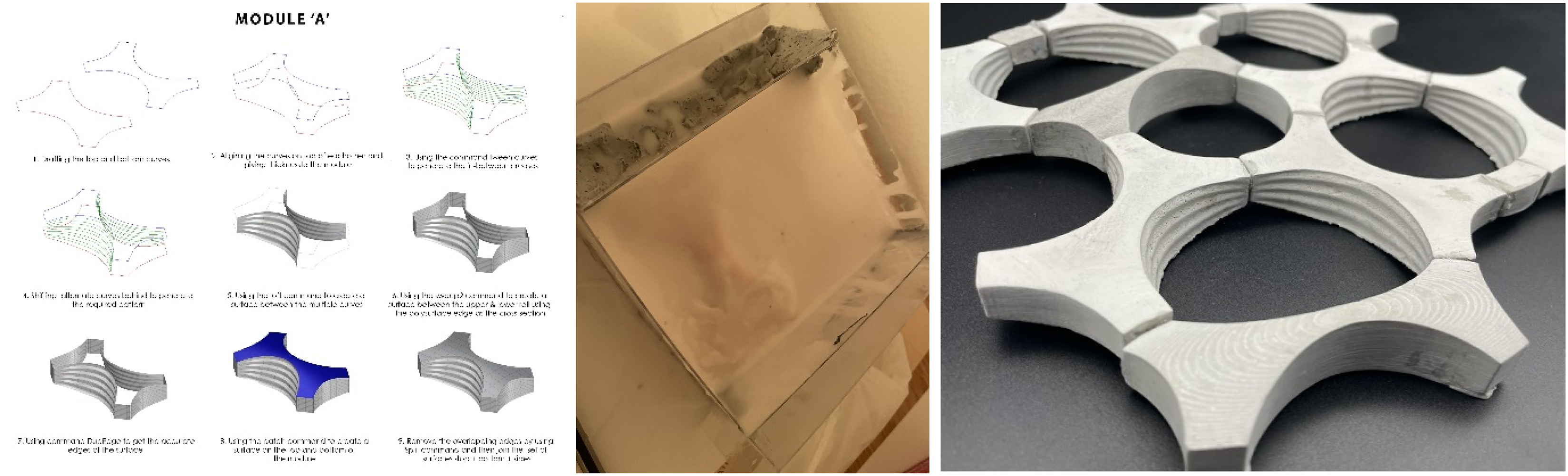
Incorporating space for failure within the syllabus is crucial when planning the course, as the learning process in making-based studios is not always linear and straight forward. Through experiencing failure, students have the opportunity to make discoveries and cultivate a profound understanding of materials and processes.
Teaching the ignored aspects of designing and fabricating building enclosures
In an anonymous survey, students were asked to reflect on the project by answering some questions related to the course and the assigned project. In response to the question of “how did your understanding of precast facades change after completing this project” some responses are summarized below and analyzed. “The main change in my understanding of the façade systems is that now I will be more critical of its structural and technical abilities of fabrication. Earlier my understanding of them was mostly concerned with the visual aspect and the sustainable sun shading aspect, but now connections and formwork would be the first things I would think of when I look at a piece of precast façade.”
This feedback underscores the instructor’s initial observation regarding the emphasis on high performance and sustainable building enclosures, while neglecting other aspects related to building enclosures such as design and fabrication of modules and molds to create cast facades elements. The student’s response indicates a developing insight into the interconnected roles of architects as both designers and builders. Initially, they primarily focused on the aesthetics and sun shading properties of a precast façade system, with fabrication methods and connection types being secondary. However, the exercise has encouraged them to pay closer attention to the latter.
Bridging the past and future while establishing a direct engagement with the fabrication reality
Two other students reflect on the value of studying historical examples. “I understand the process a bit more and how depending on the fabrication and the type of mold they use can reduce cost and labor, since this is a three-step process it requires a lot of labor.” “Learning the history of concrete façade using the 21st century tools and methods was interesting assignment. This will help us to use the construction history knowledge to mutate/redesign an element in a different and efficient way in our studio projects.”
The responses not only signify the understanding of the inherent labor involved in the conventional methods of creating precast elements but also showcase an appreciation for the knowledge embedded in construction history. They illustrate how this historical understanding can inspire students to innovate new methods of building with the help of emerging technologies. This reflection echoes the instructor’s objective of bridging the past and future through the study of historical precedents, and construction realities influence students’ design thinking.
Another student raises the disconnection between designing in a CAD environment and the fabrication of those elements: “There might be various complexities arising while precasting the element which is not evident while modeling in CAD. How the size and the geometry of the module governs the joineries and details.”
This feedback aligns with instructor’s objective of creating a middle ground pedagogy that restricts the scale and scope for fabrication to ensure a balanced design-fabrication course is offered. It acknowledges the prevailing types of courses offered at Schools of Architecture, which predominantly consist of either construction courses concentrating on creating detail drawing and wall sections, or Design-Build studios emphasizing the assembly of physical building elements. However, this project had constrained the scale and scope of construction to bridge the gap between design and fabrication.
From a different perspective and by observing and analyzing students’ work processes in the studio, it was noted that students were either stronger in using digital design tools or in conducting hands-on activities related to materials and methods. The duration for completing the project allowed either group to develop their skills in the other field. However, the students needed more support from the instructor in analyzing complex geometry and developing their skills in digital design environments. Whereas gaining skills through hands-on experimentation was mainly undertaken by the students, and the results were communicated with the instructor in person or via email. The latter can be explained based on the different nature of developing computational design skills versus developing making skills. Many making processes, such as allowing a rubber mold to dry or letting the concrete mix set take a relatively long time to be completed, which does not always fit into the duration of a four-hour studio.
Results
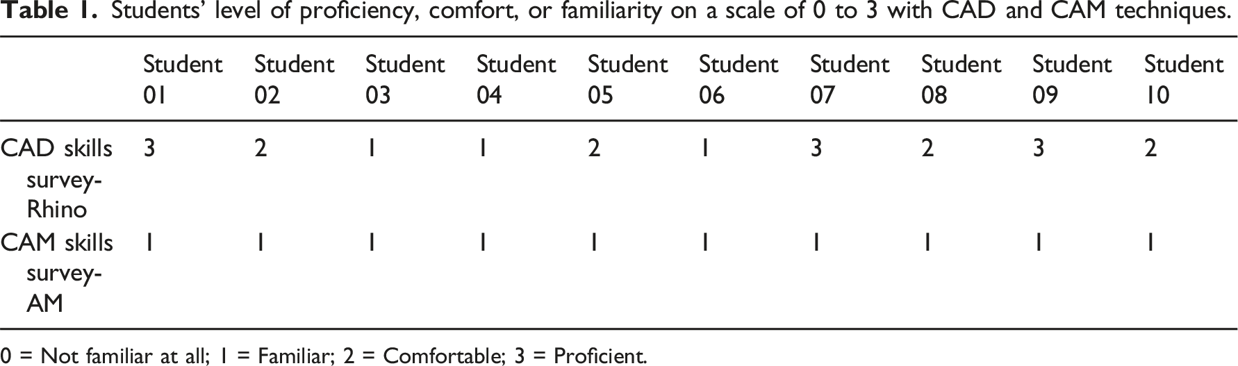
Students’ level of proficiency, comfort, or familiarity on a scale of 0 to 3 with CAD and CAM techniques.
0 = Not familiar at all; 1 = Familiar; 2 = Comfortable; 3 = Proficient.
Synthesizing the information presented in Table 1, all students expressed having some level of familiarity with Rhino. Four students out of 10 stated that they are comfortable with it, while three students indicated that they are proficient in using it. Regarding digital fabrication techniques, all students expressed that this studio has been the first digital fabrication studio that they are taking. Students’ knowledge on using 3D printing was explicitly assessed. All students expressed familiarity with the concept of 3D printing. However, they had never used it in any of their school projects, and they expressed that they had never directly operated a 3D printer.
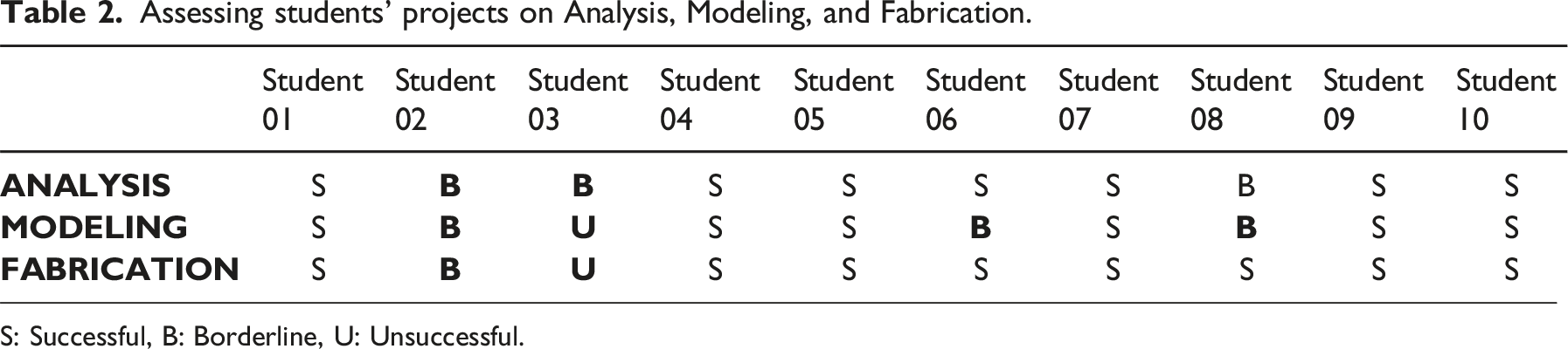
Assessing students’ projects on Analysis, Modeling, and Fabrication.
S: Successful, B: Borderline, U: Unsuccessful.
Looking at the ANALYSIS assessment in Table 2, all students received either a Successful or Borderline assessment. Regarding MODELING, only one student (student 3) received an Unsuccessful assessment. Upon revisiting the initial CAD skills of this student in Table 1, it is evident that they were only ‘familiar’ with the CAD tool. However, two other students with the same level of CAD familiarity at the beginning of the semester (students 4 and 6) achieved a Successful and Borderline MODELING assessment. Respectively, even within the small sample size, there is considerable variability in the correlation between students’ initial CAD skills and their success in delivering a CAD model. Therefore, further studies with larger sample sizes are necessary to explore this correlation.
Regarding FABRICATION, all students received either Successful or Borderline assessment except for one student. Relating the FABRICATION assessment to the initial skill level in 3D printing does not explain this correlation, as all other students were initially unfamiliar with AM. However, an Unsuccessful MODELING assessment correlated with Unsuccessful FABRICATION.
From a different perspective, although some students received Borderline assessment in CAD MODELING, they were able to compensate for that during FABRICATION phase. It is possible that through iterative hands-on activities, they manually improved upon their initial modeling approach without necessarily returning to the CAD environment for making corrections. For example, one student filled out notches of a 3D printed model with clay instead of revising the CAD model. Similarly, another student accidently discovered that one part of a two-part mold provided correct geometric proportions, without needing to revisit the CAD model and reprint it. This may explain why many students achieved Successful FABRICATION assessment, regardless of whether their MODELING scores were Successful or Borderline.
Conclusion
Almost 70 years after Saul Steinberg mocked curtain walls as ‘graph paper architecture’, architectural education mainly emphasizes educating the future generation of designers on creating high-performance curtain wall systems. This paper presents a pedagogy that foregrounds the overlooked aspects of design and fabrication of building enclosure, by focusing on studying precast façade modules. Today, in the era of computational design of non-identical elements and emergence of advanced fabrication techniques, the design of sophisticated and complex geometries for facades can extend beyond the current slim percentage found in the works of star architects. Considering the raised awareness on the negative environmental impact of concrete, future precast focuses on optimized design methods and efficient fabrication techniques. Additive manufacturing in particular, can transform precast by 3D printing the reference piece that is used in the mold making process.
This paper presents a pedagogy that bridges the past and the future by reinterpreting historical projects and recreating them using AM. In the context of REVIT product libraries or Grasshoppered Voronoi patterns, one of the objectives of analyzing historical precedents is to allow students to understand how having control over geometry at a micro level with deep understanding of the geometric constructs such as lines, curves, and cross sections, can lead to the creation of complex yet sophisticated elements. In the context of rapid prototyping where the state-of-the art 3D printers are readily available to students, another objective of the pedagogy is to demonstrate to the students the potential of AM beyond model making. The final objective of the instructor is to create a middle-ground course that goes beyond creating detail drawings of wall sections but does not become a design-build studio either. This course was envisioned to balance design’s role in its artistic sense with hands-on activities that demonstrate the labor and constraints of fabricating and constructing precast facades.
Focusing on students’ approach to CAD MODELING, and FABRICATION of precast facades presented in the precedents, the findings are summarized below: • Even within the small sample size, there is variability among the correlation of students’ initial CAD skills and their success in delivering a CAD model. This correlation requires further studies with larger sample sizes. • Regarding FABRICATION, all students achieved Successful or Borderline assessment except for one student. Relating the FABRICATION assessment to the initial skill level in 3D printing will not explain this correlation since all students were initially not familiar with AM. However, Unsuccessful CAD MODELING has led to Unsuccessful FABRICATION. • From a different perspective, some students ended up gaining Borderline assessment in CAD MODELING, but they were able to compensate for that during FABRICATION phase. Perhaps through conducting the iterative hands-on activities, they were manually improving upon their initial modeling approach without necessarily going back to the CAD environment to make revisions.
The general observations on the design-fabrication iterative loops are summarized below: • Teaching about the ignored aspects of building enclosure such as design of precast, design of mold, and fabrication allows students to develop an insight into interweaving architects’ role as designers and builders. • Studying historical precedents bridges the past and future. It helps students to understand the knowledge embedded in construction history and the embedded labor in the conventional way of creating precast elements, before innovating new ways of building with the help of emerging technologies. • Studying historical precedents establishes a direct engagement with the fabrication reality surrounding the precedents. The pedagogical underpinnings of using historic precedents imply a tectonic and tangible design thinking in mold design and mold making. • Students related the three-step mold-making process to real-world precast concrete production. Making the small-scale mockup has engaged the students in fabricating a component and constructing an assembly which is beyond making an architectural model. In fact, the students understood the act of building. • Students recognized the effects of reference piece’s manufacturing method on the mold, and then on the cast pieces. The added layers of the 3D printed positive piece registered its patterns on the mold thus the cast pieces. • The students self-learn through failure. Offering fabrication workshops will not eliminate failure altogether, it can only limit the number and scope of failures. Leaving space for failure in the syllabus is essential in planning the course.
Modifications are planned for future project development. • Learning about precast joinery is crucial, as many projects relied on perfect surfaces that could be created weak and delicate for connections. Therefore, the digital fabrication of components needs to be understood in parallel with connection details and joinery of precast elements. This includes understanding how modules are connected to the primary structure (slabs, frame) and each other. • Understanding the concept of undercut, draft angle, and the orientation of demolding was challenging for many students. It is planned to create some simple geometries to formally discuss this, instead of an ad-hoc, one-by-one discussion in desk critic. Since rubber mold has a flexible material, it can be forgiving with undercuts to some extent. Therefore, not all students grasped the idea even after completing the project. Therefore, the proposed sample would need to be made out of a rigid material. • A deeper geometry analysis for exploring multiple mold-making solutions will be valuable. This deeper analysis can be done before starting the hands-on phase to save time and materials in the making process. Also, a deeper analysis of the orientation of the mold will be helpful to achieve a controlled finish face. • One area of improvement for this project would have been investigating mold making approach for the corner modules where the façade turns.
By combining historic examples with contemporary technologies, pedagogy introduces students to the rich overlaps between the field’s subdisciplines, productively blurring boundaries between design, fabrication, assembly, and history. The resulting work inspires deep discussions about ornament, detail, form, and technology. But it is also impactful, showing students how digital technologies can be part of a wide palette of tools available to designers—and constructors. Digital fabrication methods result in revised understandings of materiality and structural textures expected by traditional craftsmanship or industrialized production. These understandings are valuable preambles for introducing new ways of fabricating precast elements towards making it more cost and labor efficient.
Footnotes
Acknowledgments
Ethical approval was sought and received from the students enrolled in the studio whose projects were included in this manuscript. I would like to thank the students enrolled in this studio for their hard work: Amir Zarei, Atousa Esmaeili, Avinash Verma, Bryant Nunez, Franchelle D'Souza, Harshini Rama Shankari Jaya Varanasi, Krishna Jayachandran Sailaja, Samruddhi Shirdhankar, Stuti Bhardwaj.
Declaration of conflicting interests
The author(s) declared no potential conflicts of interest with respect to the research, authorship, and/or publication of this article.
Funding
The author(s) disclosed receipt of the following financial support for the research, authorship, and/or publication of this article: I would like to acknowledge the financial support from Illinois School of Architecture for providing the materials needed for this studio.
