
Abstract
Drilling practices in Tarim Oilfield of China have shown that the combined use of a Positive Displacement Motor (PDM) and a Power Drive System can significantly enhance wellbore trajectory control and drilling efficiency, but it is likely to cause drill tools failure. Preliminary studies once attributed this failure to High-Frequency Torsional Oscillation (HFTO), but the actual failure morphology does not match HFTO induced failure features. This paper, based on finite element model (FEM) of drill string dynamics, investigates the mechanical mechanism behind the failure of the stabilizer’s threaded joint in a Bottom Hole Assembly (BHA) equipped with a PDM and a Power Drive System. The results show that when stick-slip vibration occurs, the drill tool at the fracture position experiences severe lateral vibration with a frequency as high as 211.4 Hz, and the maximum dynamic bending stress reaches 148.6 MPa in which the maximum additional bending stress caused by collision reaches 126.1 MPa when the closest rub-impact point is 2.49 m above the upper end of the stabilizer. This indicates that it is precisely these high-frequency lateral vibrations (HFLV) that induce high-frequency alternating stress within the threaded joint, thereby causing fatigue damage and ultimately leading to drill tool fracture.
Keywords
Introduction
Exploration and development of oil and gas resources in China are progressively advancing toward deep and ultra-deep formations, with a continual increase in the number of ultra-deep wells (well depth: 6000–9000 m) and extra-deep wells (well depth > 9000 m).1–3 The completion of these wells is impossible without the drilling system, as shown in the simple diagram in Figure 1. Drill string is a principal component of the entire drilling system, and will be subjected to complex vibrations during the process of rotating and breaking rocks. The failure of the drill string is one of the most common complex situations in drilling operations. In severe cases, it can lead to the destruction of the wellbore, often resulting in significant waste of drilling time and costs. The increase in well depth will lead to a higher slenderness ratio of the drill string, a harsher working environment, and more pronounced nonlinear vibrations, collectively posing a severe challenge to the dynamic safety of the drill string. The dynamic safety of the drill string is closely related to the complex vibrations and the corresponding control measures. In addition to bit bounce, whirl, and stick–slip, advanced downhole measurement technology has revealed another highly destructive form of vibration: High-Frequency Torsional Oscillation (HFTO), with a frequency range of 20–700 Hz. 4 Field data indicate that failures of electronic components, 45° cracks in drill collars, damage to bit teeth, and loosening of threaded connections are all closely associated with HFTO.
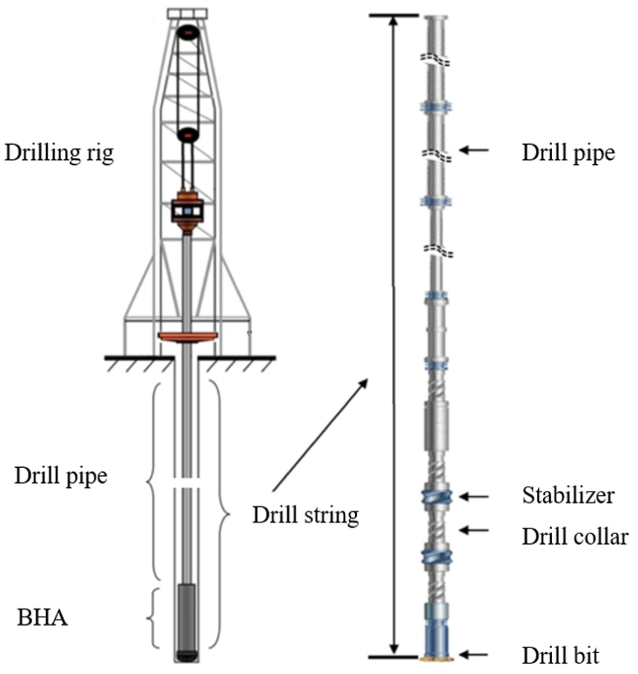
Schematic of rotary drilling system.
From 2022 to 2024, multiple stabilizer joint breakage accidents occurred in the Tarim Oilfield of China. A typical feature of these accidents is the application of a combination assembly of “PDC bit + rotary steerable system + Positive Displacement Motor (PDM).” Initially, engineers attributed all these failures to HFTO. However, subsequent research has revealed that this failure analysis is not consistent with the observed failure patterns.
Here, the well XX-102 is taken as an illustrative example. A bottom hole assembly (BHA) consisting of a “PDC bit + Power Drive System + PDM” was deployed for well trajectory control and to enhance the rate of penetration (ROP), with a designed depth of 5660.0 m. When drilling reached a depth of 4896.00 m, the box end of the integral matching stabilizer on the rotary steerable drilling system fractured. The fish length was 4.07 m. The schematic diagram of BHA and its fracture location are shown in Figure 2, and the fracture section of drill tool is shown in Figure 3. As illustrated, the fracture surface exhibits a relatively flat and smooth region, showing the typical characteristics of fatigue failure, including the crack initiation, stable crack propagation, and the final fracture.
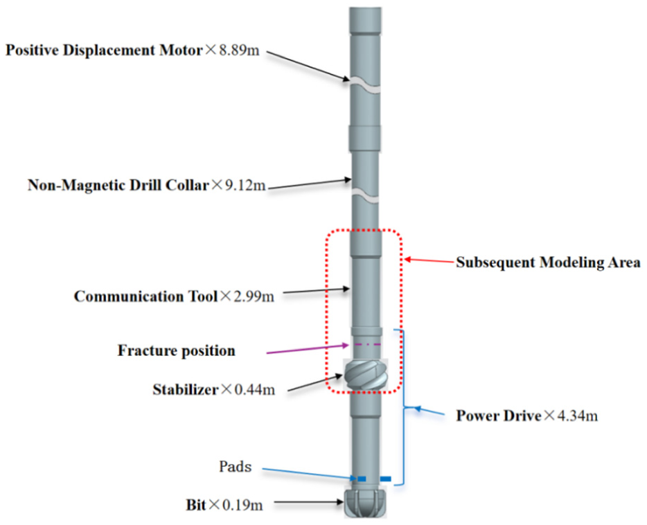
Schematic diagram of BHA used in well XX-102 and the fracture position of the drill tool.

Fracture section of the drill tool.
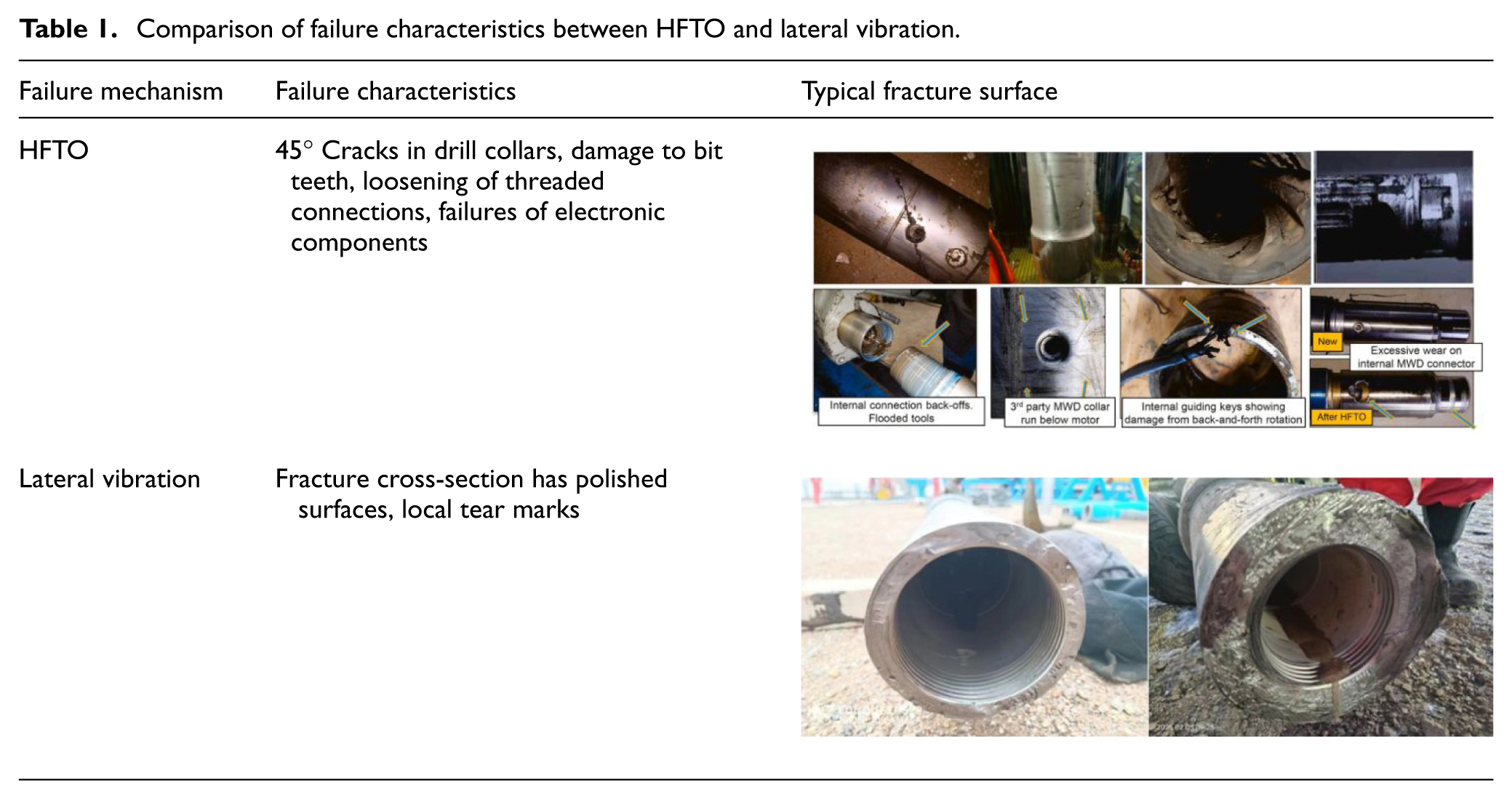
Similar fracture failures of threaded joints in downhole drill tools have occurred in multiple cases. In response, many oilfield engineers have been actively analyzing the causes of these failures, with particular attention paid to the potential connection between such failures and HFTO. The failures caused by HFTO exhibit typical characteristics of torque-induced failures, including the failure of the shell of drill tools and the failure of the downhole sensors, etc. For drill collars or the shell of some drill tools, the failure characteristics usually produce inclined cracks at approximately 45° to the axis, 4 as shown in Table 1. While the failure characteristics caused by lateral vibration as the main factor are that the fracture cross-section has polished surfaces and local tear marks. If the failure is completely caused by torsional alternating stress, such marks will not be obvious.
Comparison of failure characteristics between HFTO and lateral vibration.
It is beyond doubt that the aforementioned failure is related to the complex vibrations of the drill string. To clarify its mechanical mechanism, it is necessary to conduct in-depth research on the dynamic characteristics of the drill string, which is a highly complex and arduous task. The dynamic characteristics of the drill string involve multiple vibration modes of drill string movement and numerous influencing factors, including bit-rock interaction,5,6 drill string-wellbore frictional contact,7,8 the influence of drilling fluid dynamics, 9 and the effect of mass eccentricity, 10 among other factors. Relevant research has attracted much attention, and many scholars have conducted in-depth studies in this field.
The study of drill string dynamics has evolved through a complex progression from single-mode vibration to two-modes coupling and finally to three-modes coupling, 11 with research methodologies including analytical methods,12,13 experimental methods,14,15 numerical simulation techniques,16,17 and downhole vibration measurement technologies. 4
Given that drill strings possess not only an extreme slenderness ratio but also inherently exhibit strong geometric and contact nonlinearities, coupled with complex boundary conditions and excitation types, both analytical and experimental methods face severe limitations. Consequently, they can only serve as auxiliary methods. At present, researchers tend to adopt the in-situ measurement method to determine the vibration characteristics of the drill string underground, 18 and use numerical simulation method to analyze the vibration mechanism of the drill string, optimizing the structural parameters and drilling parameters of the drill string to ensure its dynamic safety. 19
Numerical simulation methods for drill string dynamics primarily encompass the finite element method and multi-body dynamics approach.20–24 The fundamental approach of the finite element method for solving drill string dynamics is based on Hamilton’s principle. This approach considers both the geometric and contact nonlinearities of the drill string to establish a dynamic model. 20 Most of the subsequent modeling work adopted this method, but additional factors were incorporated. For example, gyroscopic effects, axial-bending coupling, torsional-bending coupling, and gravity stiffening effects were accounted for to simulate self-excited stick-slip vibrations of the drill string and to compute its transient vibrational response under various excitations. 21 On this basis, the steady-state and transient responses of the drill string were calculated using multiple methods, including direct solution of the structure matrix and solution via the node iteration method. The former has a clear conceptual basis and has been widely used. As a typical example, the Wilson-theta direct time integration method was employed to investigate solution techniques for large-scale nonlinear systems characterized by uncertainties and dynamic boundaries. 22
However, for a system like the drill string, which has an extremely high slenderness ratio and strong nonlinearity, the calculation of dynamic features involves large sparse matrix inversion operation. When the length of the drill string exceeds a certain extent, the number of drill string elements becomes very large. For computers in the last century, matrix inversion operations were very time-consuming, requiring extremely high computing power to perform operations on large sparse matrices. It is precisely for this reason that the iterative method for straight beam (two-elements and three-nodes iteration method) was developed, 20 and it has significantly advanced research on drill string dynamics. Later, the initial curvature of the drill string was incorporated to establish a model combining both straight beam and spatial curved beam elements, and to develop a simulation program capable of dynamic analysis for drill strings exceeding 7000 m. 23 The evolution of these computational methods has enabled their successful application in challenging field cases. Recent studies have confirmed the application of this finite element methodology to analyze the dynamic characteristics of the drill string in China’s first over 10,000 m ultra-deep well—the SDTK-1 Well. 24 With a maximum modeled drill string length reached 10,910 m,24,25 this approach played a key role in ensuring safe drilling operations throughout this landmark project. Using the FEM to model the petroleum drill string system, simplifying the slender drill string into beam elements is currently a commonly adopted effective approach. However, the classical Euler-Bernoulli beam theory often neglects the high-order effects of transverse shear deformation, which may lead to insufficient accuracy when the drill string is subjected to composite loads. Therefore, the modern refined shear models and high-order theories in advanced composite material structural mechanics are of great significance for improving the accuracy of the drill string dynamics model.26,27
Apart from the finite element method, multi-body dynamics has also been successfully applied to the analysis of drill string dynamics. 28 The typical study focused on analyzing the dynamic behavior of the drill string with a rotary steerable drilling system.
The failure of drilling components under complex vibrational conditions is one of the primary research focuses. Critical integrity issues are studied in components such as drill pipes, drill collars, stabilizers, ROP enhancing tools, and marine risers. Some typical examples are fatigue failure of drill pipes during deep drilling or harsh-environment operations, 29 and the fatigue failure in drilling assemblies used in large-diameter sections of deep and ultra-deep wells. 30 Experiments have shown that the primary cause of such fatigue failures is the interaction between the drill string and the borehole wall. 29 It should be pointed out that such failures often occur in curved wellbores, where drill tools are subjected to tensile and bending loads. 31 In this context, the failure problem of the drilling tool can be summarized as the stress intensity and the fatigue growth of a circumferential semi-elliptical surface crack in a hollow cylinder subjected to rotary bending and tension. 3D FEM and the Walker fatigue growth rate law were used to study the evolution of parameters characterizing the process of crack propagation. 32
Although numerous scholars and researchers have conducted extensive studies on various failure mechanisms of drill strings, none of the relevant findings can fully explain the drill tool failure problem described in this study. It can be said that the drill tool failure problem of the BHA with the Power Drive system and PDM encountered in well XX-102 is a newly emerging drill tool failure, which requires further investigation. To clarify the mechanical mechanism of the above-mentioned failure problems, this work analyzes the vibration characteristics of the drill string at the failure position through simulation of the three-dimensional coupled drill string dynamics, with a focus on determining the frequency of the drill string vibration. Meanwhile, the bending stress endured by the adjacent drill tools of the failed stabilizer in curved wellbores was calculated by using 3D FEM software. This comprehensive analytical method revealed the mechanical mechanism underlying the fracture of the stabilizer’s threaded connection in a BHA with a PDM and the Power Drive system. The findings can provide a theoretical foundation for enhancing the dynamic safety of such drilling assemblies.
Formulation and solution of drill string dynamics model
To study the failure mechanism of the drill string, it is necessary to first carry out the analysis of the dynamic characteristics of the drill string. For this reason, this section introduces the establishment of the drill string dynamics model and presents a numerical method for efficiently solving the model.
Assumptions
In order to establish the dynamic model of drill strings, the following assumptions were made: (1) The deformation of the drill string is characterized by large displacement and small strain. (2) The cross-section of the hole is circular. (3) The drill string can be discretized into three-dimensional elastic beam elements. (4) The influence induced by drill pipe joint is ignored. (5) The deformation of the drill string conforms to the Euler-Bernoulli beam theory.
Coordinate systems
To facilitate the description of the complex motion of the drill string, three coordinate systems are established: the global coordinate system O-XYZ, the element coordinate system o-xyz, and the body-fixed coordinate system o′-x′y′z′.
(1) Global coordinate system O-XYZ: The global coordinate system is defined as an Earth-fixed system. Its origin, O, is located at the center of the wellhead. The X-axis is aligned with the direction of gravity, pointing vertically downward. The Y-axis points toward true north, and the Z-axis points toward true east. This coordinate system is represented by the black axes in Figure 4(a).
(2) Element coordinate system o-xyz: The element coordinate system is established to describe the drill string’s motion relative to the borehole axis. Its origin, o, is located on the borehole axis. The x-axis is tangent to the borehole axis, pointing downward toward the bit. The y-axis aligns with the direction pointing to high side of the wellbore, and then the z-axis can be determined by the right-hand rule. This coordinate system is represented by the orange axes in Figure 4(a).
(3) Body-fixed coordinate system o′-x′y′z′: the origin, o′, is located on the drill string axis. The x′-axis is tangent to the drill string axis, pointing toward the bit. The y′-axis coincides with the y-axis of the element system when the drill string is undeformed. The z′-axis is similarly determined by the right-hand rule, as shown in Figure 4(b). It is crucial to note that the body-fixed coordinate system continuously changes with the dynamic response of the drill string.
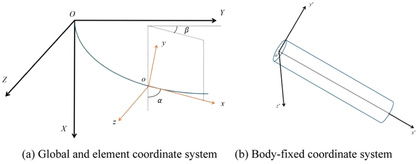
Coordinate system: (a) global and element coordinate system and (b) body-fixed coordinate system.
Dynamic model of drill string
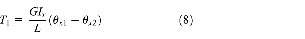
Based on Hamilton’s principle, the governing equations that describe drill string dynamics can be expressed as:

where
The mass matrix

where
The stiffness matrix

where

where
The damping matrix

where
Boundary conditions
The boundary conditions at the wellhead are as follows. The drill string is laterally supported by hinges and axially connected by springs. In the torsional direction, it is subjected to the torque provided by the top drive.
The boundary conditions at the bit are modeled as pinned in the lateral direction, whereas the axial and torsional excitations arise from the bit-rock interaction. 33 The weight on bit (WOB) is given by:

where
The expression of the torque on bit (TOB) reads 34 :

where

where
When the radial displacement of the drill string exceeds the annular clearance between the drill string and the wellbore, the drill string is constrained by the borehole wall. The contact model between the drill string and the borehole wall follows Hertz contact theory, which reads 20 :
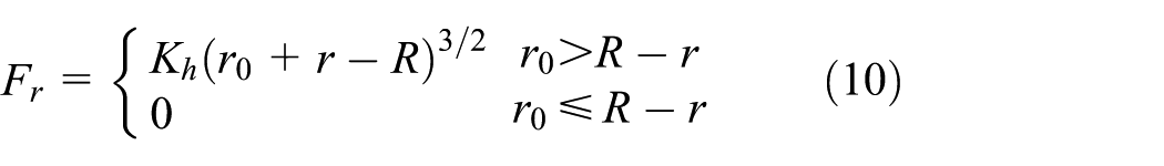


where
For drill strings with rotary steerable drilling system, the excitation of the rotary steerable drilling system also needs to be considered. Figure 5 is a schematic diagram illustrating the operating principle of the Power Drive system. For each full revolution of the drill string, the three pads in the bias unit sequentially contact the borehole wall. As each pad is cyclically activated every 120° of drill string rotation, the resultant contact force on the borehole wall exhibits minor fluctuations.
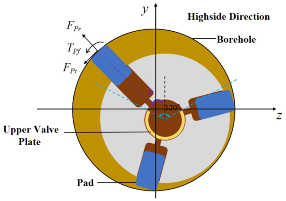
Schematic illustration of actuating pads in a rotary steerable drilling system. 35
The actuation force from the Power Drive System over one revolution of the drill string can be expressed as 35 :
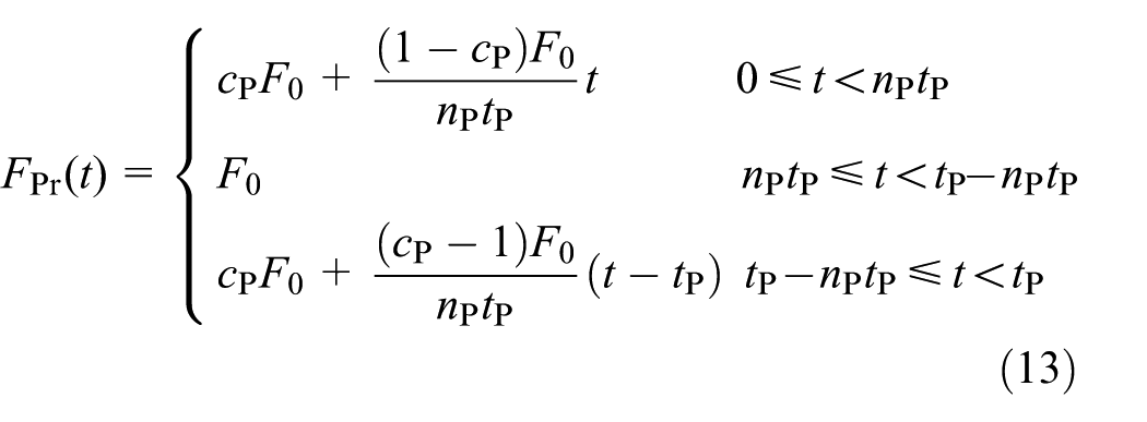
where
Solution method
The solution to the above model is essentially a problem of discretization in both the time and the spatial domains. This study employs the Newmark method for temporal discretization and the finite element method for spatial discretization.
(1) Newmark method 36
The Newmark method is a numerical integration approach employed to solve dynamical equations, which transforms second-order ordinary differential equations into a system of algebraic equations at discrete time steps. It possesses the advantages of unconditional stability and high efficiency.
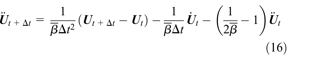
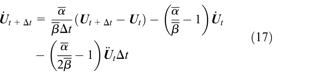
The Newmark method assumes that the acceleration of the drill string varies linearly over a time interval. The velocity


where
From equations (14) and (15), the acceleration
Substituting equations (16) and (17) into equation (1), we obtain:
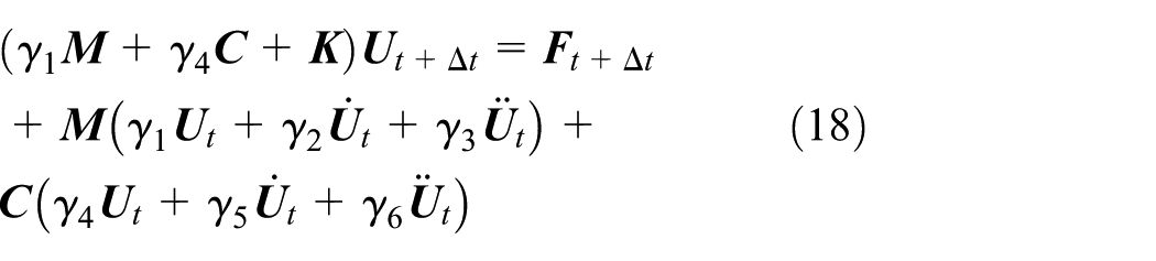
where
With the known displacement
(2) Node iteration method
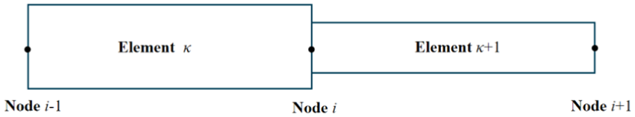
The finite element method is used to discretize the entire drill string into hundreds or thousands of elements. The calculation of the node displacement from equation (18) with direct integration method involves inverse operations of large structure matrices, which is computationally intensive and might even be unable to solve the problem. Therefore, a node iteration method is employed to determine the displacement at each time step in this study, 23 as shown in Figure 6. This is the so-called two-element and three-node iteration method.
Node iteration method.
Based on the displacement

Then an important task needs to be carried out, that is, to determine whether the displacement of this node exceeds the borehole wall. If it does, the displacement of this point should be reduced to ensure that this node is on the wellbore wall.
The node iteration method has a unique advantage in dealing with the contact problem between drill string and borehole wall, but the drawback is that the calculation consumes a considerable amount of time. To solve this problem, this paper employs the super-relaxed method to accelerate the simulation. Specifically, the SOR node iteration method in Wang et al. 2 is used to calculate the displacement at each time step. In order to ensure the accuracy of the calculation, an iterative calculation error of 10−7 was set. This can ensure the accuracy of each iteration step and is also the common practice in this field.
Dynamic characteristics and bending stress analysis of the drill tool at the fracture position
Figure 7 shows the 3D well trajectory of well XX-102, which is a typical directional well with a maximum inclination angle of approximately 42.78°, and the kickoff point is located at 3392.75 m. To visually display the variation in the curvature of the wellbore, the wellbore curvature (also known as dogleg severity, DLS) was superimposed on the wellbore trajectory curve. The maximum wellbore curvature of this well is 9.36°/30 m, corresponding to a well depth of 4649.81 m.
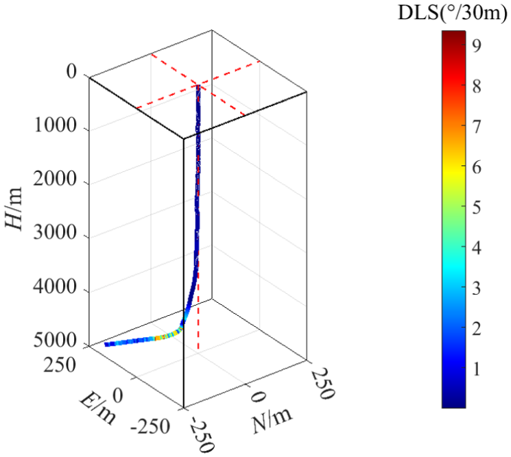
3D well trajectory.
Dynamic characteristics of the drill tool at the fracture position
The drill string used at the well depth of 4896.00 m is as follows: Φ 168.3 mm PDC Bit × 0.19 m +Φ 139.0 mm (55.0 mm) Power Drive System × 4.34 m +Φ 123.0 mm (80.0 mm) Telemetry Sub × 2.99 m +Φ 120.0 mm (70.0 mm) Non-Magnetic Drill Collar × 9.12 m +Φ 127.0 mm (57.0 mm) PDM × 8.89 m +Φ 101.6 mm (63.5 mm) Heavy-Weight Drill Pipe × 171.47 m +Φ 101.6 mm (82.3 mm) Drill Pipe × 2318.67 m +Φ 149.2 mm (129.9 mm) Drill Pipe × 2380.33 m. The numbers in parentheses are the inner diameters of assembly components.
During the drilling process, the applied WOB, the surface rotation speed and the density of the drilling fluid are 92.0 kN, 50.0 RPM and 1930.0 kg/m3, respectively. The rotary speed of the PDM is 100.0 RPM. The time step is 0.002 s, and the total calculation time is 60.0 s. The Rayleigh damping coefficient
The heterogeneity of the formation leads to complex interaction mechanisms between the drill bit and the rock, thereby resulting in highly complex downhole dynamic behaviors of the drill string, such as whirl and stick-slip. As is well known, both whirl and stick-slip are severe forms of drill string vibrations and represent the two most damaging types of complex vibrations to the drill string. Therefore, the analysis here is conducted based on these two scenarios: whirl and stick-slip.
Dynamic characteristics of the drill string during whirl vibration
The whirl trajectory and velocity at the fracture position of the drill string are presented in Figure 8. This position is relatively close to the stabilizer, causing the drill tool at this location to primarily whirl around the wellbore axis. Moreover, due to the large well inclination angle (42.36°), the whirl trajectory is affected by gravity and leans toward the lower side of the wellbore.
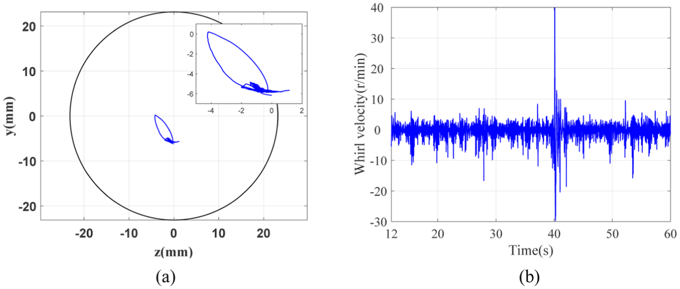
Whirl trajectory (a) and whirl speed (b) of the drill tool at the fracture position.
When the drill string experiences whirl motion, the velocity of the drill string along the y and z directions at the fracture position is shown in Figure 9. It can be seen from the figure that the velocity distributions along the two directions have similar fluctuation features but with different ranges. The velocity along the y direction mainly fluctuates within the range of −0.05 to 0.05 m/s and shows obvious periodicity. In particular, the velocity varies significantly at 42 and 52 s, ranging from −0.125 to 0.08 m/s and from −0.09 to 0.09 m/s respectively. The velocity along the z direction mainly fluctuates within the range of −0.02 to 0.02 m/s, with obvious periodicity. At 40 s, the velocity becomes more pronounced, and the fluctuation range is between −0.08 and 0.06 m/s. The Fast Fourier Transform (FFT) was performed on these lateral velocities, and the obtained spectral results are shown in Figure 10. The results indicate that dominant frequencies in the velocity signals along the y and z directions are below 5.0 Hz, which indicates that the lateral vibration frequency at this position is relatively low when whirl vibration occurs.
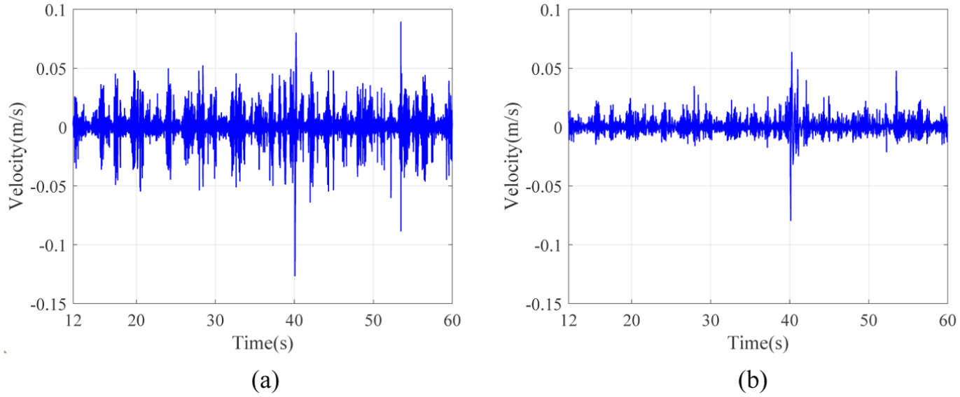
Velocities of the drill tool along the y direction (a) and z direction (b) at the fracture position during whirl vibration.
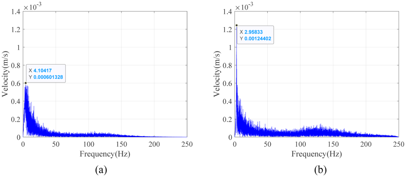
FFT analysis of the velocities of the drill tool along the y direction (a) and z direction (b) at the fracture position during whirl vibration.
Dynamic characteristics of the drill string during stick-slip oscillations
Under specific conditions, the drill string experiences stick-slip vibrations. Figure 11 shows the bit rotary speed and the torque at the fracture position during stick-slips. The results indicate that the stick-slip period is approximately 5.7 s, with a stick phase of about 3.3 s and a slip phase of 2.4 s. The rotary speed reaches a peak of 163.13 r/min, which is 3.3 times the surface rotary speed of drill string. The torque fluctuates between 1.97 and 3.93 kN·m, with an average value of 2.66 kN·m.

Rotary speed (a) and torque at the fracture position (b) of drill string during stick-slip oscillations.
The lateral velocity at the fracture position of drill string during stick-slip vibrations are shown in Figure 12. The maximum velocities along the y- and z-directions reach 2.70 and 4.88 m/s respectively during the period of 17.0 to 17.7 s. The corresponding frequency spectra are presented in Figure 13, from which it can be seen that the velocity signals along both the y and z directions have dominant peaks at 211.4 Hz, indicating that the drill tool at this position has experienced a high frequency lateral vibration with a frequency of 211.4 Hz.

Velocities of the drill tool at the fracture position along the y direction (a) and z direction (b) during stick-slip oscillations.

Frequency spectra at the fracture position of drill string along the y direction (a) and z direction (b) during stick-slip oscillations.
The above results indicate that for the given drill string the stick-slip vibrations excite high-frequency lateral vibrations, which is an important factor leading to the failure of the drill tool. There is another crucial factor that causes the failure of the drill tool, which is the magnitude of the stress variation.
Bending stress of the drill tool at fractured position
When rotates in a high DLS well section, the drill string not only deforms to conform to the wellbore geometry but also collides with the wellbore wall, thus inevitably affecting the alternating bending stress. For the stabilizer and its adjacent drill tools shown in Figure 14, there are many contact states, with four limiting scenarios worthy of attention. For the convenience of description, point B is used to represent the contact point between the stabilizer and the borehole wall, while point P represents the nearest contact point between the drill tool adjacent to the stabilizer and the borehole wall. Figure 14(a) and (b) show the scenarios where points B and P are on the same side. In Figure 14(a), both points B and P are located on the raised borehole wall, whereas in Figure 14(b), both points B and P are located on the concave borehole wall. Figure 14(c) and (d) show the scenarios where points B and P are located on opposite sides. In Figure 14(c), point B is on the protruding borehole wall, while in Figure 14(d), point B is on the concave borehole wall.

Schematic diagram of a bending drill tool in a curved wellbore: (a) Points B and P on convex borehole wall, (b) Points B and P on concave borehole wall, (c) Point B on convex wall, point P on concave wall, and (d) Point B on concave wall, point P on convex wall.
As shown in the typical situation in Figure 14(a), the stabilizer leans against the protruding side of the borehole wall, and the adjacent drill tools (the SP section in the figure, generally the body of stabilizer or drill collar) are subjected to significant bending stress. This stress can be decomposed into two components: the curvature-equivalent bending stress arising from borehole curvature and the additional bending stress stemming from collision.
(1) Curvature-equivalent bending stress: The stress generated by the bending when the axis of the drill string is parallel to the axis of the curved wellbore during its movement (black line indicating the stabilizer adjacent drill tools).
(2) Additional bending stress: This refers to the bending stress increment generated in the adjacent drill tools as it continues to move laterally toward the borehole wall, with the stabilizer as the fulcrum. The stress reaches its maximum value when the drill tool comes into contact with the protruding side wall of the wellbore. As shown in Figure 14(a), the red line represents the drill tools adjacent to the stabilizer. It is evident that a smaller distance between the contact point B and the stabilizer,
The curvature-equivalent bending stress can be expressed as:
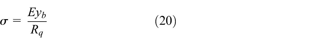
where
As illustrated in Figure 14, when the drill tool contacts the borehole wall at point P, the curvature of section SP exceeds the wellbore curvature, and the bending radius (
The established finite element model is listed in Figure 15, where position A1 designates the top end of the telemetry sub, position B1 marks the top of the Power Drive system, and position C1 indicates the bottom end of the stabilizer blade. The model contains a total of 46,741 nodes and 31,680 units. The boundary condition is to constrain all the degrees of freedom of the stabilizer. The calculation process is divided into two sequential analysis steps.
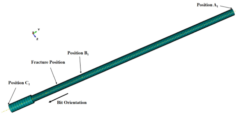
Finite element model of drill tools.
(1) Calculation of the curvature-equivalent bending stress
According to the previous definition, the curvature-equivalent bending stress refers to the bending stress experienced by the drill string at the critical section when its axis is assumed to be parallel to the wellbore axis. For this drill string, the operation interval extends from 4826.00 to 4896.00 m. Within this interval, the maximum wellbore curvature is 3.02°/30 m, occurring at a measured depth of 4835.80 m, as shown in Figure 16.

Borehole curvature in the well section from 4826.00 to 4896.00 m.
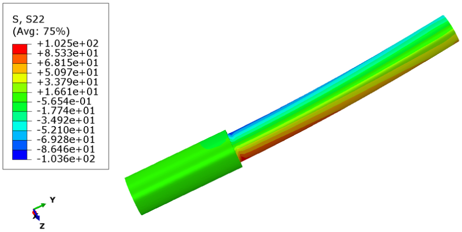
A constant torque is applied at positions A1 and B1 to maintain the drill string curvature consistent with that of the wellbore. Under this loading condition, the bending stress distribution within the critical section of the drill string is shown in Figure 17. The maximum curvature-equivalent bending stress reaches 22.5 MPa, which agrees with the analytical solution derived from equation (20).

Curvature-equivalent bending stress in critical section.
(2) Calculation of additional bending stress
According to the previous definition, when the drill tools initially conform to wellbore curvature and subsequently moves laterally toward the borehole wall, contact induces an additional bending stress. In other words, once the drill tool touches the wellbore at point P, the tools within the critical section experience an extra bending load.
For the example given in this paper, when the well depth reaches 4839.87 m, the wellbore curvature at the corresponding fracture position is 3.02°/30 m. The calculated whirl trajectories of drill tools at the stabilizer, the fracture position, position B1 and position A1 are presented in Figure 18. The blue curves represent the whirl trajectories, while the gray region represents the allowable motion envelop for drill tools.

Whirl trajectories of drill tools near the fracture position.
Under the given simulation conditions, due to the effect of gravity, the whirl trajectory of drill tools moves toward the lower side of the wellbore. Multiple contacts between drill tools and wellbore wall occurred at position A1 (7.52 m from the bit), whereas no contact is observed at either the fracture position or position B1 (4.53 m from the bit). However, it should be emphasized that during the actual operation process, the vibration behavior of the drill string is highly complex and continually evolving, which means that drill tools located between A1 and B1 may collide and coming into contact with the borehole wall.
To quantify the additional bending stress induced by different collision occurring at different positions within A1–B1 interval, the distances from the contact position P to position B1 were set as 0.50, 1.00, 1.50, 2.00, 2.50, and 2.99 m (corresponding to position A1). Since the distance from position B1 to the upper end of the stabilizer’s blade is 0.99 m, the distances

Bending stress in the critical section of the drill tool corresponding to different
Bending stress in the critical section of the drill tool corresponding to different
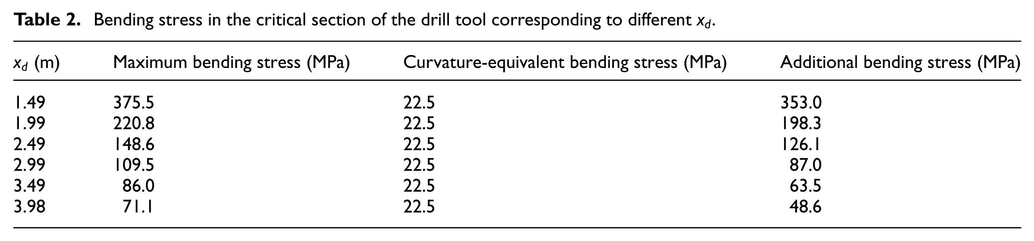
The variation of the additional bending stress with respect to
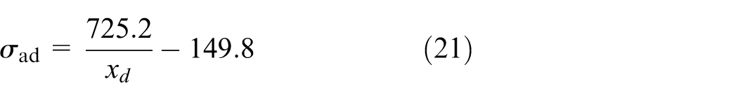
where

Figure 20 shows that the drill tool in the critical section experience a greater additional bending stress as
In most cases, the initial assumption is that the most likely scenario involves collision and contact between drill tools and the protruding wall of a curved borehole, as shown in Figure 14(a), where B and P are on the same side of borehole. However, the vibration of the downhole drill tools is intense and their movements are complex. The cases shown in Figure 14(b)–(d) are also possible to take place. For this study, the scenario corresponding to Figure 14(b) was analyzed. When the value of
Bending stress on drill tools in the critical section corresponding to the situation of Figure 14(b).
Figure 13(c) and 13(d) present two possible limit conditions. In such cases, the forces acting on drill tools are particularly complex. Due to the length of the article, these two situations are not analyzed in this study.
Failure mechanism analysis
From the previous analysis, it can be observed that in the well section of 4826.00–4896.00 m, the maximum wellbore curvature is 3.02°/30 m. When the BHA with PDM and Power Drive system rotates in this well section and is in the state shown in Figure 14(a), the drill tool in the dangerous section experiences a curvature-equivalent bending stress of 22.5 MPa and an additional bending stress of 126.1 MPa, resulting in a maximum bending stress up to 148.6 MPa (tensile). When the drill string is in the condition shown in Figure 14(b), the maximum compressive stress at the location in the dangerous section that originally endured the maximum stress is approximately 103.6 MPa (compressive).
Therefore, due to the combined effects of wellbore curvature and the lateral motion of drill tools, the dynamic bending stress in the critical section of drill tools ranges from −103.6 MPa (compressive) to 148.6 MPa (tensile). Moreover, as seen in Figures 10 and 11, during stick-slip vibration, the amplitude of lateral velocity variation in the y and z-directions at the fracture position increase significantly between 17.0 and 17.7 s, with a lateral vibration frequency reaching 211.4 Hz. It is precisely this high-frequency lateral vibration (HFLV) that induces high-frequency alternating stress within the drill tool, leading to fatigue damage. This damage is highly likely to initiate micro-cracks in local areas of the drill tool, which progressively propagate as drilling continues, eventually leading to the fracture of the drill tool.
In summary, for the examples given in this paper, there is currently no evidence of the existence of HFTO. Instead, the HFLV associated with stick-slips is identified as the main cause of drill tool failure. Consequently, mitigating stick-slip vibration, suppressing the HFLV, and lowering the bending stress on the drill tool are key measures to prevent such failures.
Discussion
Analysis of the fracture at the stabilizer’s threaded connection of the BHA (equipped with a PDM and a set of Power Drive System) in the XX-102 well demonstrates that when stick-slip vibration occurs, lateral vibrations with frequencies reaching 211.4 Hz are generated along both the y and z directions. In contrast, when the BHA does not experience stick-slip vibration, the frequency of lateral vibration is relatively low. Correspondingly, during the drilling process of the well section from 4826.00 to 4896.00 m, drill tools in the dangerous section developed a curvature equivalent bending stress of 22.5 MPa due to wellbore bending and an additional bending stress exceeding 100.0 MPa caused by lateral vibration. This means that the bending stress caused by the curvature of the wellbore is less than the additional bending stress caused by the impact. From the above analysis, it can be seen that the additional bending stress caused by the impact is closely related to
Another important factor influencing the additional bending stress is the outer diameter of the stabilizer. When the outer diameter of the stabilizer is large, the bending degree of the drilling tools adjacent to the stabilizer’s blade will be greater, thereby increasing the additional bending stress. That is to say, without affecting the control effect of the wellbore trajectory, the outer diameter of stabilizer should be minimized as far as possible to control the additional bending stress for the BHA considered in this paper.
Moreover, since the BHA experiences more intense whirl motion in slipping phase when the stick-slip vibration occurs, the corresponding lateral vibration of drill string becomes more intense and higher in frequency. Therefore, minimizing the stick-slip vibration is the key to controlling the high-frequency lateral vibration and the additional bending stress. This can be realized only by adjusting drilling parameters or optimizing the BHA configuration, but it should be noted that in actual engineering, the optimization of drilling parameters needs to meet practical conditions, such as rate-of-penetration increase, deviation control, and safety goals. In this paper, only the outer diameter of stabilizer was suggested to decreased based on the result that the drill string can be kept away from the resonance frequencies of HFLV.
In the end, the mechanical mechanism underlying the fracture failure of the stabilizer’s threaded joint lies in the HFLV of the drill tool at the fracture position, which induces high-frequency alternating stress, thereby causing fatigue damage and eventually developing into fracture of the drill tools.
Conclusion
For the BHA presented in this article, the failure of the stabilizer threaded joint can be attributed to the high-frequency alternating bending stress induced by HFLV, and the main cause is the additional bending stress resulting from the collision between the drill tool and wellbore wall. This kind of additional bending stress is particularly evident in the slipping phase of the stick-slip vibration, which provides us with a very important idea for solving this type of failure. In summary, it can be stated in two aspects.
(1) Optimizing the BHA structure and drilling parameters to mitigate vibration, especially the stick-slip vibration.
(2) Minimizing the outer diameter of the stabilizer used in this paper as far as possible to control the additional bending stress.
It should be pointed out that the model established in this paper is relatively macroscopic. It did not conduct local detailed modeling of the specific structure of the stabilizer thread joint’s thread teeth, nor did it optimize the application parameters for the existing drill string structure. These aspects need to be further improved.
Footnotes
Appendix
Handling Editor: Aarthy Esakkiappan
Funding
The authors disclosed receipt of the following financial support for the research, authorship, and/or publication of this article: This research was supported by the National Natural Science Foundation of China (52174003, 52574006) and Subproject of the National Science and Technology Major Project of China (2024ZD1401805).
Declaration of conflicting interests
The authors declared the following potential conflicts of interest with respect to the research, authorship, and/or publication of this article: He Zhang is another joint corresponding author. He is currently employed by Itasca Consulting Group, Inc. However, the research presented in this paper was conducted independently and does not reflect the views, interests, or activities of Itasca. The content and conclusions are solely the responsibility of the author and do not represent the position or endorsement of the employer.