
Abstract
To address the issue of reduced transmission performance of magnetorheological clutches at high temperatures, a novel magnetorheological clutch with a variable working gap controlled by shape memory alloy springs is proposed. By utilizing the compression force generated by shape memory alloy springs at elevated temperatures, the working gap configuration of the clutch is converted from a single-cylinder structure to a double-cylinder structure, which effectively enhances the transmission torque. In addition, the frictional torque generated by the compressive force of the shape memory alloy springs contributes to the overall enhancement of transmission torque. Based on finite element analysis of the magnetic field, the shear yield stress of the magnetorheological fluid in each working gap under different structural configurations was calculated. The theoretical model of transmission torque for the device was deduced. The torque under each operating mode was calculated and compared with the experimental results. Experimental results demonstrate that a single shape memory alloy spring can generate a maximum compression force of 59.5 N. When the excitation coil current is 1 A and the temperature is 100°C, the torque of the single-cylinder magnetorheological clutch is 10.60 N·m, while that of the double-cylinder magnetorheological clutch reaches 24.99 N·m, representing a 135.8% improvement in transmission performance.
Introduction
Magnetorheological fluid (MRF) represents a new type of magnetic intelligent material, whose rheological properties and microstructure can be controlled by an external magnetic field. 1 Upon application of a magnetic field, MRFs transition from a Newtonian fluid state to a solid-like state and develop a controllable shear yield stress. This phenomenon is continuously controllable and reversible, making MRFs ideal candidates for torque transmission media in magnetorheological clutches, 2 brakes, 3 and other mechatronic devices.4,5 However, the transmission performance of MRF tends to degrade at high temperature.6–10 Meanwhile, shape memory alloys (SMAs), another class of advanced intelligent materials, can gradually recover their pre-deformation shape when heated above a certain temperature. When constrained, this shape recovery process generates an external output force, and the shape memory effect exhibits reversibility comparable to that of the MRF rheological transition described above.11–13
Owing to their superior torque transmission capabilities, MRFs have attracted extensive investigations into their engineering applications.14–16 Nguyen and Choi 17 combined finite element analysis with optimization algorithms to refine the design of conventional MRF brakes, including disk-type, cylindrical, hybrid, and T-shaped configurations, aiming to maximize braking torque output. Rizzo et al. 18 proposed a new permanent magnet-based MRF clutch and designed a specialized gap geometry to reduce the torque friction losses during the clutch disengagement state. Sun et al. 19 developed a novel high-torque elliptic-arc multi-disk MRF coupling structure and established a corresponding mechanical torque transmission model. Qin et al. 20 designed an innovative multi-drum MRF brake, which activates a larger shear area within a compact volume to achieve higher braking torque. Song et al. 21 established a comprehensive design protocol for MRF brakes with adjustable gaps, and the experimental results indicated that the influence of fluid gap on brake performance varies significantly under different current intensities.
During MRF device operation, excessive heat generation inevitably degrades the transmission performance of MRF. To mitigate this issue and enhance torque output, physical heat dissipation strategies have been adopted. Wang et al. 22 developed a water-cooled MRF brake, where circulating cooling water within the brake housing dissipates heat from the MRF, thereby improving braking stability and performance. In terms of structural optimization, Dai et al. 23 proposed a hybrid MRF clutch integrating disk and cylindrical configurations, ensuring that all surfaces of the drive plate contribute to torque transmission. Nguyen et al. 24 designed an MRF brake structure with multiple coils arranged on both sides of the brake housing; compared with traditional MRF brakes, this multi-coil configuration delivers higher braking torque while maintaining a compact footprint. Beyond these structural and thermal management strategies, the fundamental relationship between operating temperature and MR clutch torque output has also received direct experimental attention. The influence of temperature on the torque characteristics of MR clutches has been systematically investigated by Bucchi et al., 25 who conducted experimental measurements on a permanent magnet MR clutch heated up to 80°C and established a temperature-dependent torque model based on Arrhenius law, demonstrating that transmitted torque decreases significantly with increasing temperature and providing a foundational quantitative basis for understanding thermal degradation in MR clutch devices. In a related earlier contribution, Bucchi et al. 26 proposed a passive magneto-thermo-mechanical coupling in which conventional compression springs and SMA springs work in opposition to control the engagement state of an MR clutch depending on ambient temperature, with the SMA springs designed to disengage the coupling when temperature exceeds 90°C so as to protect an engine-driven vacuum pump from overloading. This work represents a conceptually important antecedent to the present study in that it also combines SMA springs and MR fluid within a single device to achieve temperature-responsive behavior, although the operating logic differs fundamentally from the present design: in Bucchi et al. the SMA springs act to disengage the coupling at high temperature to avoid overloading, whereas in the present study the SMA springs are used to actively enhance the torque transmission capacity at high temperature by converting the working gap from a single-cylinder to a double-cylinder configuration. Beyond this difference in operating logic, the two designs also differ fundamentally in their functional objectives, as the SMA springs in Bucchi et al. serve solely as a passive safety mechanism to interrupt torque transmission when a threshold is exceeded, whereas in the present study the SMA springs serve as an active structural reconfiguration actuator that dynamically converts the working gap geometry from single-cylinder to double-cylinder in direct response to the temperature rise, targeting torque enhancement rather than torque interruption as the primary response to thermal loading. Furthermore, Bucchi et al. 27 investigated the geometry optimization of MR clutches operated by excitation coils, comparing single-cylinder and multi-disk gap configurations with internal and external coil placements, and used finite element models to determine the optimal coil and gap geometry for maximum transmissible torque within a given device volume. The comparison between single-cylinder and multi-disk configurations in that study provides useful context for the structural motivation of the double-cylinder design proposed in the present work, and the FEA-based design methodology adopted here follows a similar approach to the magnetic circuit analysis framework established in that work, extended to a variable-gap configuration in which the magnetic circuit analysis must account for two distinct structural states and the effective working lengths of the gaps must be determined from the simulated flux density distribution rather than from the nominal geometric dimensions alone.
In parallel with these thermal management and structural optimization efforts, the composite application of MRF and SMA as two complementary classes of smart materials has attracted growing attention in recent years. Xiong and Huang 28 proposed a magnetorheological braking system in which SMA springs automatically increase the volume fraction of magnetic particles as temperature rises, thereby compensating for the reduction in shear yield stress and maintaining stable braking performance across a wide temperature range. Chen et al. 29 further developed an adjustable-gap MR brake driven by an electrothermal SMA spring, demonstrating that the squeeze force output of the SMA spring can be used to dynamically alter the MRF working gap and regulate braking torque in response to temperature changes. A recent systematic review by Wu et al. 30 on the structural development of MRF brakes and clutches identified temperature-induced MRF performance degradation as one of the most critical unresolved challenges, pointing out that integrating smart actuation mechanisms to achieve adaptive structural response represents a promising research direction. In terms of specific structural innovations, Wu et al. 31 developed a multi-pole MRF clutch integrating permanent magnets and excitation coils, demonstrating that hybrid magnetization configurations can achieve a substantially wider torque adjustment range than single-source excitation while maintaining precise closed-loop torque control through a PID controller. Sarvarmaleki et al. 32 provided a comprehensive review of MRF clutch design methodologies and identified the thermal management of MRF under prolonged high-load operation as one of the most critical unsolved challenges, a conclusion that directly motivates the temperature-adaptive structural design proposed in the present study. The composite application of MRF and SMA has thus evolved from early passive protection concepts toward increasingly integrated functional designs in which the shape memory effect serves as an active structural reconfiguration mechanism that dynamically adjusts the working geometry of MRF devices in response to thermal conditions. A representative recent example of this direction is the waste heat-reusing MR clutch with SMA springs designed by Chen et al., 33 which directly converts waste heat into friction torque generated by SMA spring compression to compensate for MRF performance degradation, effectively mitigating the negative impact of temperature rise and improving the transmission performance and energy utilization efficiency of the MR clutch. In that design, however, the working gap geometry remains fixed throughout operation and the torque compensation relies solely on the supplementary friction torque produced by the SMA springs, without altering the fundamental MRF shear transmission mechanism or expanding the MRF working area. The torque enhancement achievable by that approach is therefore inherently limited by the magnitude of the SMA compression force and the friction coefficient of the contact interface. The present study differs from this approach in three fundamental respects. First, the SMA springs actively reconfigure the working gap geometry from single-cylinder to double-cylinder, substantially expanding the MRF shear area beyond what friction compensation alone can achieve. Second, the primary torque enhancement mechanism is the expansion of the MRF shear area, with the friction torque from the SMA springs serving only as a secondary contribution. Third, the achievable torque enhancement is determined by the geometric dimensions of the additional gap surfaces rather than by friction interface parameters, and can therefore be scaled more freely by adjusting the structural dimensions. These three distinctions together demonstrate that the present design represents a fundamentally different approach rather than an incremental modification of the waste heat reuse concept proposed by Chen et al.
Motivated by the above analysis, this study proposes a novel MRF clutch in which SMA springs serve as thermally driven actuators to convert the working gap from a single-cylinder configuration to a double-cylinder configuration at elevated temperatures, while simultaneously generating auxiliary friction torque through the compressive force of the SMA springs. The combined effect of the expanded MRF shear area and the supplementary friction torque not only improves the transmission torque of the MRF clutch at elevated temperatures but also reduces the sensitivity of the overall transmission performance to temperature rise.
Structure design and magnetic simulation of MRF clutch
Structure design of MRF clutch
The schematic diagram of the proposed novel MRF clutch with a SMA spring controlled variable gap is illustrated in Figure 1. In the initial state, the excitation coil is de-energized, and the MRF is contained within a 2 mm working gap between the bearing shells and the outer cylinder. Under this condition, the viscous drag torque of the MRF in the absence of a magnetic field is insufficient to transmit motion from the driving shaft to the driven shaft. When the excitation coil is energized, the magnetic particles in the MRF align into chain-like structures under the resulting magnetic field, enabling the MRF to develop shear stress and allowing the driving shaft to transmit motion to the driven shaft. The transmitted torque increases monotonically with the input current amplitude.

Schematic diagram of MRF clutch.
During prolonged operation of the clutch, the operating temperature will exceed 50°C, and the shear yield stress of the MRF will gradually decrease at elevated temperatures. Meanwhile, the SMA springs are heated and begin to push the bearing shells toward the limit blocks, allowing a portion of the MRF to flow through the interstices among the bearing shells into the gap between the bearing shells and the inner cylinder. The MRF simultaneously fills two 1 mm gaps (one between the bearing shells and the outer cylinder, and the other between the bearing shells and the inner cylinder), as shown in Figure 2. The increased number of working gaps will enhance the torque transmission capacity of the MRF clutch. As the temperature continues to rise, the SMA springs drive the bearing shells to compress the limit block and generate additional friction torque.

Process of changing MRF working gap.
When the excitation coil is de-energized, the MRF reverts to a Newtonian fluid state and ceases to transmit torque. As the temperature decreases, the SMA springs recover their initial configuration and the bearing shells separate from the limit blocks under the action of the return springs, resulting in complete torque interruption.
Within the MRF clutch, four bearing shells are connected to the driving shaft via four dovetail sliders. Each bearing shell is actuated by two SMA springs and is capable of radial movement. In the initial state, a 0.1 mm gap is maintained between the bearing shells and the inner cylinder, eliminating relative friction.
Magnetic circuit simulation of MRF clutch
To ensure that the chain-formation direction of magnetic particles in the MRF is perpendicular to the shear direction during torque transmission, the magnetic circuit of the clutch is analyzed by simulation. The simplified model of the MRF clutch in state of the single-cylinder condition is shown in Figure 3(a), while that in double-cylinder condition is presented in Figure 3(b). The dimension parameters of the simplified models are summarized in Table 1.

Simplified model of the MRF clutch under different cylinder conditions: (a) single-cylinder working gap and (b) double-cylinder working gap.
Dimension parameters of the simplified models (unit: mm).

To enhance the accuracy of the magnetic field analysis, the nonlinear magnetic permeability of the materials used in the device was incorporated into the finite element analysis (FEA) through experimentally measured magnetization curves. The magnetization curves of the materials used in the input shaft and shell sections are shown in Figure 4(a). The MRF was supplied by Chongqing Materials Research Institute, named MRF-J01T, with the material properties listed in Table 2. The magnetization curve of MRF-J01T is shown in Figure 4(b) and can be approximated through curve fitting as:
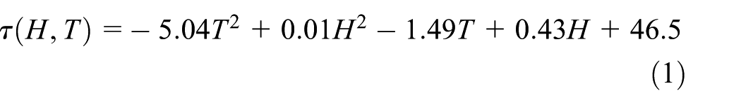
where
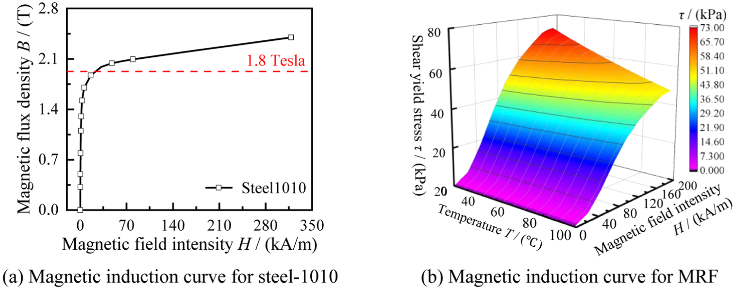
Material characteristic curve: (a) magnetic induction curve for steel-1010 and (b) magnetic induction curve for MRF.
Material parameters of MRF-J01T.

For the magnetic field analysis model of the variable-gap MRF clutch, the surrounding region was set as air with a relative permeability of 1. The coil was designed with 400 turns, and the currents in the two coils were set to be in the same direction. Under different coil currents, the magnetic field distributions of the MRF clutch with varying working gap thicknesses, derived from transient magnetic field FEA, are shown in Figure 5.

Result of magnetic circuit simulation: (a) single-cylinder and (b) double-cylinder.
The magnetic flux intensity distribution and flow direction of the magnetic flux when I = 1A are also presented in Figure 5. It can be observed from Figure 5 that in both the single-cylinder and double-cylinder states of the device, the magnetic flux surrounds the excitation coil to form a closed loop, which orthogonally penetrates the MRF working gap. This result verifies the rationality of the structural design and material selection. The magnetic flux density distribution of the MRF is illustrated in Figure 6.

Magnetic flux intensity distribution of MRF: (a) single-cylinder MRF gap area and (b) double-cylinder MRF gap area.
As shown in Figure 6, due to the magnetic isolation effect of the aluminum material in the middle of the bearing shells, the magnetic flux density of the MRF in the middle regions of gaps h1 and h2 is extremely low. To quantitatively define the effective working area, a threshold criterion is established based on the minimum magnetic flux density required to activate the chain-like structure formation of magnetic particles in MRF-J01T. According to the magnetization curve of MRF-J01T shown in Figure 4(b), the shear yield stress begins to rise appreciably when the magnetic flux density exceeds approximately 0.10 T, below which the MRF essentially behaves as a Newtonian fluid and contributes negligible transmission torque. Therefore, regions where the local magnetic flux density falls below 0.10 T are defined as non-effective working zones in this study. Based on the simulation results in Figure 6, the middle region of gap h1 influenced by the aluminum isolation layer exhibits magnetic flux density values below 0.10 T and is accordingly excluded from the effective working length calculation. Similarly, the upper portion of gap h2 also falls below this threshold due to magnetic flux leakage through the bearing shells. The remaining axial extents of the gaps, where the magnetic flux density consistently exceeds 0.10 T, are taken as the effective working lengths and are used in the torque calculation model in Section 3.2. The magnetic flux density in the effective working gap h1 varies from 0.21 T (minimum) to 0.29 T (maximum). For gap h2, the effective region yields a range of 0.03 T (minimum) to 0.30 T (maximum), with the lower-density portion at the upper end excluded. For gap h3, it varies from 0.20 T (minimum) to 0.30 T (maximum), and the entire axial length of h3 satisfies the threshold criterion and is fully included as effective working area. Owing to the lower magnetic resistance of the bearing shells compared to that of the MRF and the short working length of gap h2, a portion of the magnetic flux penetrates the bearing shells into gap h3, which explains the uneven distribution of magnetic flux density along the axial direction of gap h2 observed in Figure 6. Based on the threshold criterion and the magnetic flux density distribution extracted from the simulation results, the effective working length of each gap is determined as follows. For gap h1, the middle region influenced by the aluminum isolation layer spans approximately 16 mm along the axial direction, within which the magnetic flux density falls below 0.10 T and is therefore excluded, leaving an effective working length of approximately 104 mm out of the total axial length of 120 mm. For gap h2, the upper portion where magnetic flux leakage through the bearing shells reduces the local flux density below the threshold spans approximately 10 mm, and the remaining effective working length is approximately 110 mm. For gap h3, the magnetic flux density exceeds 0.10 T throughout the entire axial extent, so the full length of 120 mm is taken as the effective working length. These effective working lengths are subsequently used as the value of Le in the torque calculation model expressed in equation (7) through equation (10). Combined with Figure 4 and the magnetic flux density data of the MRF in each gap, the shear yield stress of the MRF in working gaps h1, h2, and h3 can be obtained, as presented in Figure 7.

Relationship between shear yield stress and axial distance.
Theoretical analysis of transmission property
Theoretical model of SMA spring driven force
During long-term operation and coil heating, the temperature in the working gap of the MRF clutch gradually increases. When the temperature reaches the starting temperature of austenite transformation of the SMA at 50°C, the SMA springs begin to extend and drive the bearing shells toward the stop block, thereby converting the MRF working gap h1 into gaps h2 and h3. The transformation process from single-cylinder to double-cylinder mode is actuated by SMA springs. It should be noted that the SMA spring compression force characterization presented in Section 4 was conducted in plain hydraulic oil without an applied magnetic field. This differs from the actual operating condition, in which the bearing shells must move radially through MRF that is simultaneously subjected to the excitation field. Under the applied magnetic field, the MRF develops a shear yield stress that acts on the outer surface of the bearing shells and generates resistance to shell motion during the gap reconfiguration process. Since conducting a dedicated experiment that simultaneously applies the excitation magnetic field, heats the SMA springs through the full austenite transformation range, and measures the net driving force against an MRF-filled gap would require a complete integrated prototype that is not yet available at the current research stage, the operability of the device under working conditions is instead verified through a detailed analytical force margin analysis based on the measured SMA compression force data and the MRF material properties characterized in this study, as detailed below. During the radial inward movement of the bearing shells, the outer surface of the shells is in contact with the MRF in gap h1, and the primary resistance to shell motion arises from the shear yield stress of the MRF acting on the shell contact surface under the applied magnetic field. Taking the full cylindrical outer surface of the bearing shell assembly as the contact area, the total contact area is calculated as 2πR2(L1−L2), which equals approximately 325 cm2. Under an excitation current of 1 A, the shear yield stress of MRF-J01T at 100°C is approximately 5.49 kPa as derived from equation (1), giving a total resistive shear force of approximately 179.0 N acting on the bearing shell assembly. The viscous drag force arising from the low-speed radial motion of the shells can be estimated from equation (5), which gives a MRF viscosity of approximately 0.18 Pa·s at 100°C. For the cylindrical outer surface of the bearing shell assembly moving radially at approximately 0.1 mm/s across a 2 mm gap, the resulting viscous drag force is on the order of 0.03 N, which is more than three orders of magnitude smaller than the resistive shear force of 179.0 N and is therefore negligible in the force balance calculation. At 100°C, the eight SMA springs collectively produce a total compression force of 476.0 N, which exceeds the resistive shear force of 179.0 N by a factor of approximately 2.7, confirming that the SMA driving force provides sufficient margin to complete the gap reconfiguration at the maximum operating temperature. To provide a more complete picture of the force margin across the full operating range, a systematic analysis is presented here for the temperature range of 50°C to 100°C under both full and partial excitation current conditions. At 50°C, the total compression force of the eight SMA springs is approximately 202.6 N based on the model in equation (2), while the resistive shear force under the maximum excitation current of 1 A is approximately 271.7 N, giving a force margin below unity at this temperature. However, as the temperature rises the SMA compression force increases rapidly while the MRF shear yield stress decreases simultaneously, and the driving force crosses the resistive force threshold at approximately 63°C under full 1 A excitation. Beyond this temperature, the force margin increases progressively, reaching 1.27 at 70°C, 1.77 at 80°C, and 2.66 at 100°C, confirming that the SMA driving force provides sufficient margin to sustain and complete the gap reconfiguration across the upper portion of the operating temperature range. The condition at 50°C under full 1 A excitation, where the SMA compression force of 202.6 N is slightly below the resistive shear force of 271.7 N, warrants further clarification. The total radial displacement required to complete the gap reconfiguration is only 1 mm, and since the temperature rise from 50°C to 63°C develops gradually over several minutes under sustained operation, the bearing shells have sufficient time to complete this displacement as the net driving force transitions from slightly negative at 50°C to positive at 63°C. Furthermore, any partial displacement completed before 63°C proportionally reduces both the remaining travel distance and the corresponding resistive force, further accelerating completion of the transition as temperature rises. The gap reconfiguration is therefore completed within the temperature rise from 50°C to 63°C under full 1 A excitation, and the device operates with substantial force margin under all other conditions considered.
Under partial excitation current conditions, the MRF resistive force is substantially lower, and at 0.5 A the force margin already exceeds unity at 50°C and reaches 4.44 at 100°C, confirming that gap reconfiguration proceeds without delay throughout the entire temperature range under all partial excitation conditions. With the operability of the gap reconfiguration process established through the above force margin analysis, the driving force model of the SMA springs can be formulated to quantify the compression force at each operating temperature.
The driving force

where d is the wire diameter of the SMA spring with d equal to 1 mm, n is the effective number of turns with n equal to 6, D is the pitch diameter with D equal to 8.6 mm, x is the displacement of the bearing shell with x equal to 1 mm, and L is the amount of spring expansion. The shear modulus

where

where

Friction produced by SMA springs.
It can be observed from Figure 8 that the SMA springs start to push the bearing shells against the limit block at 50°C, generating friction when the bearing shells rotate. In the temperature range of 55°C to 70°C, the friction force generated by a single SMA spring increases rapidly from 0.5 to 4.4 N, after which the increasing trend slows down with further temperature elevation. At 100°C, the maximum friction force of a single SMA spring reaches 6.0 N, and that of eight SMA springs is 47.6 N.
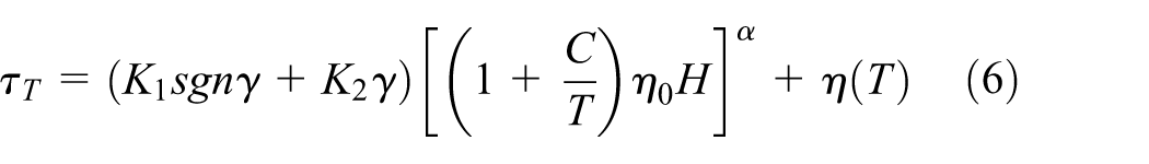
With the increase of temperature, the properties of MRF are also affected. Elevated temperature intensifies the thermal motion of carrier liquid molecules, leading to a reduction in the interparticle magnetic interactions and the overall cohesion of the particle chains. Consequently, high temperature decreases the viscosity of the MRF. The temperature-dependent viscosity of MRF is described by the following relationship proposed in 35 :

where
Elevated temperature also reduces the shear yield stress of the MRF. After testing 10 MRF samples, Sun et al. 36 found that under a given magnetic field intensity and shear strain rate, the shear yield stress of the MRF decreases with increasing temperature. The relationship between the shear yield stress of the MRF, magnetic field, and temperature is expressed as:
where

Relationship between torque and temperature.

Relationship between torque and current.
The relationship between the shear yield stress of the MRF and temperature under the magnetic field intensity generated by a 1 A current was calculated, as shown in Figure 11. In the temperature range of 20°C to 50°C, the shear yield stress decreases from 8.92 to 8.34 kPa; subsequently, the decreasing rate accelerates, with the shear yield stress dropping from 8.34 to 5.49 kPa in the range of 50°C to 100°C. This indicates that an increase in operating temperature will indeed degrade the transmission performance of the MRF.

Relationship between shear yield stress and temperature.
Theoretical model of transmission torque
Before establishing the torque transmission model, it is necessary to examine whether the centrifugal loading on the bearing shells during rotation has a significant influence on the gap geometry and shell force equilibrium, as this directly affects the validity of the structural assumptions underlying the torque model. The centrifugal force acting on a single bearing shell can be expressed as:

where m is the mass of the bearing shell, R is the radial distance from the rotation axis to the centroid of the shell, and ω is the angular velocity of the driving shaft. It is necessary to first clarify the direction of the centrifugal force and its role in the shell force balance under each operating state. The centrifugal force acts radially outward on each bearing shell, tending to push the shells toward the outer cylinder and reduce gap h1 below its nominal 2 mm value. In the de-energized low-temperature state, the return spring restoring force acts radially inward and is the sole force resisting this outward displacement, so the shell force balance requires the return spring restoring force to exceed the centrifugal force to maintain the nominal gap geometry. In the energized high-temperature state, the SMA springs drive the bearing shells radially inward, and the centrifugal force acts in the opposite direction to the SMA driving force, adding to the total resistance alongside the MRF resistive shear force and the return spring restoring force. Based on the geometry of the bearing shells, which are fabricated from aluminum with a radial thickness of approximately 4 mm and an axial length of 126 mm, the mass of a single bearing shell is estimated to be no greater than 200 g, representing a conservative upper bound, and the centroid radius is approximately 52 mm based on the structural dimensions in Table 1. At the experimental operating speed of approximately 60 rpm, the centrifugal force on a single bearing shell is estimated to be at most 0.4 N, which represents less than 2.1% of the combined return spring restoring force of 20.0 N per shell, confirming that centrifugal loading at the experimental operating speed is negligible.
To provide a more complete treatment, the centrifugal force is incorporated into the radial force balance of the bearing shells alongside the SMA spring force and the return spring force. In the de-energized state at low temperature, the force balance of each bearing shell requires that the return spring restoring force exceeds the centrifugal force mRω2, and using the conservative upper-bound shell mass of 200 g and centroid radius of 52 mm with a return spring restoring force of approximately 20.0 N per shell, the maximum speed below which the de-energized gap h1 remains unchanged at 2 mm is approximately 419 rpm, confirming that no unintended increase in viscous drag torque occurs in the de-energized state across the intended operating speed range. In the energized state at elevated temperature, the centrifugal force acts in the same outward direction as the return spring force and therefore adds to the total resistance that the SMA driving force must overcome. At 100°C and 1 A excitation, the centrifugal contribution at 60 rpm is 0.4 N compared to a total resistance of approximately 199.0 N and an SMA driving force of 476.0 N, meaning the centrifugal force increases the total resistance by less than 0.2% and reduces the force margin from 2.66 to 2.39, which remains well within an acceptable range. Even at 200 rpm the centrifugal force increases the total resistance by only 4.6 N and the force margin remains at 2.34, confirming that the gap reconfiguration capability is robust against centrifugal loading across the intended speed range. It is also necessary to assess whether the centrifugal force produces a measurable radial displacement of the bearing shells that would alter the nominal 2 mm gap geometry assumed in the FEA magnetic field analysis. With a centrifugal force of 0.4 N at 60 rpm compared to a return spring restoring force of 20.0 N, the fractional shell displacement due to centrifugal loading is approximately 2.0% of the spring preload travel, corresponding to a gap width reduction of less than 0.04 mm. This represents less than 2.0% of the nominal 2 mm gap width, and based on the inverse relationship between gap reluctance and magnetic flux density, the resulting change in flux density within the working gap is less than 1%. This level of variation is negligible relative to the axial flux density distribution shown in Figure 6 and has no practical effect on the shear yield stress distribution or the torque predictions derived from the FEA analysis.
It should be noted that the centrifugal force increases proportionally with the square of the rotational speed, and at speeds exceeding approximately 130 rpm the centrifugal force would begin to approach 10% of the return spring restoring force, at which point its influence on gap geometry would warrant more careful consideration. The proposed device is therefore best suited to low-speed transmission applications where the driving shaft speed remains below approximately 100 rpm, consistent with the low-speed high-torque requirements of applications such as industrial forming machines and collaborative robot joints discussed in Section 5. For applications requiring higher rotational speeds, the return spring stiffness should be increased accordingly and the shell force balance should be re-evaluated to verify that the gap geometry remains within the design specification.
For the single-cylinder configuration, the transmitted torque of the MRF clutch is provided solely by the MRF shear torque in gap h1. In contrast, the total transmitted torque of the double-cylinder configuration comprises three contributions, namely the MRF shear torque in gap h2, the MRF shear torque in gap h3, and the friction torque generated by the SMA springs.
The torque transmitted by the cylindrical MRF can be expressed as 37 :
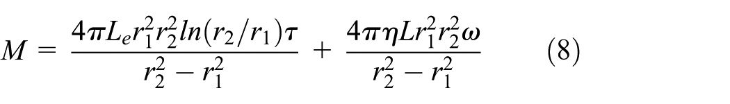
where

For the double-cylinder configuration, the torque provided by the MRF in gap h2 is expressed as equation (10):

The torque provided by the MRF in gap h3 is given by equation (11):

The friction torque generated by the 8 SMA springs is calculated by equation (12):

Therefore, when the MRF clutch switches to the double-cylinder configuration, the total transmitted torque is determined by equation (13):

Using the dimensional parameters of the clutch listed in Table 1, the transmitted torque under different operating modes with temperature was calculated, by combining equations (5)–(13). When

Transmitted torque under different operating modes.
For the fixed single-cylinder configuration of the MRF clutch, it can be observed from Figure 12 that the transmitted torque varies slightly within the temperature range of 20°C to 50°C. As temperature increases from 50°C to 100°C, the transmitted torque decreases sharply from 18.86 to 12.10 N·m, representing a 38% reduction in the torque capacity of the MR fluid at 100°C relative to 50°C. A more detailed examination reveals that this reduction is not uniform across the full temperature range. In the low-temperature range of 20°C to 50°C, the average attenuation rate is approximately 0.011 N·m per degree Celsius, indicating that MRF transmission performance remains largely stable. In the high-temperature range of 50°C to 100°C, the average attenuation rate increases to approximately 0.135 N·m per degree Celsius, more than 12 times higher than in the low-temperature range, with the most pronounced attenuation occurring between 50°C and 70°C. The local average attenuation rate in the 90°C to 100°C interval is approximately 0.043 N·m per degree Celsius, representing only 32% of the overall high-temperature average, and the instantaneous attenuation rate at 100°C, estimated from the theoretical torque values at 95°C and 100°C of approximately 12.30 and 12.10 N·m respectively, is approximately 0.040 N·m per degree Celsius, confirming that the attenuation rate has largely stabilized near 100°C as the thermal degradation of the MRF approaches its limiting rheological behavior.
This reduction in attenuation rate at elevated temperatures is physically consistent with the behavior of the shear yield stress shown in Figure 11, where the rate of decrease of shear yield stress with temperature also becomes less steep in the upper portion of the operating range as the thermal degradation of the MRF approaches a plateau governed by the limiting rheological behavior of the carrier liquid at high temperature. At 100°C, the torque level is only 63% of the value at 50°C, confirming that operation at elevated temperatures without any compensating mechanism leads to severe degradation of the transmission capability of the single-cylinder MRF clutch. When the temperature exceeds 50°C, the SMA springs actuate the clutch to switch from the single-cylinder to the double-cylinder configuration, leading to an increase in torque from 19.43 to 28.99 N·m. Subsequently, the torque transmitted by MRF decreases gradually with the further increase of temperature, reaching 22.37 N·m at 100°C. After considering the friction torque generated by the compressive force of the SMA springs, the overall torque still shows a decreasing trend with increasing temperature, but it is slightly higher than that of the double-cylinder configuration without friction torque. At 100°C, the actual total torque of the clutch is 24.99 N·m, which is approximately 106.5% higher than that of the fixed single-cylinder configuration. This effectively avoids the degradation of the overall transmission performance at high temperatures.
Experiment analysis
Experimental system
In order to characterize the driving force of SMA springs under heating, an experimental system was established as illustrated in Figure 13(a). An SMA spring and a resistance wire were placed in a beaker filled with hydraulic oil, with the SMA spring inserted inside the resistance wire coil. A current of 2 A was supplied to the resistance wire to apply an electric heating load, thereby simulating the working environment of the SMA spring. One end of the SMA spring was fixed, while a 1 mm gap was maintained between the other end and the probe of the force gage. The compression force of the SMA spring was measured using a force gage, and the thermometer probe was immersed in the hydraulic oil to monitor the operating temperature of the SMA spring.

Experimental system: (a) experimental setup for SMA spring drive force and (b) experimental platform for single-cylinder MRF clutch performance testing.
To evaluate the transmission performance of the single-cylinder MRF clutch, an experimental platform was constructed as shown in Figure 13(b). This platform mainly consisted of a MRF clutch, a torque sensor, a motor, a reducer, a DC power supply, and a dynamic torque indicator. The key parameters of the MRF clutch were as follows: the number of turns of the excitation coil was 400, the working gap of the MRF was 2 mm, the outer radius of the inner cylinder was 54 mm, and the length of the working gap was 120 mm. The maximum measurement range of the torque sensor was 200.0 N·m. After assembling the experimental equipment, a current ranging from 0 to 1 A was applied incrementally to the excitation coil. Due to the prolonged test duration and repeated test cycles, heat generated by the excitation coil and other components may degrade the performance of the MRF. Therefore, the influence of temperature on the experimental results must be considered.
Experimental results
In the SMA spring compression force experiment, the relationship between compression force and temperature was obtained through repeated tests, as shown in Figure 14. As can be observed from Figure 14, the theoretical values of the SMA spring compression force are in good agreement with the experimental values. When 2 A current was applied to the resistance wire, the operating temperature of the SMA spring increased gradually. With the rise in temperature, the experimental compression force of the SMA spring could be divided into three distinct stages. In the first stage from 30°C to 50°C, the compression force increases slightly. In the second stage from 50°C to 70°C, the compression force increases sharply from 2.8 to 45.8 N. In the third stage from 70°C to 100°C, the compression force increases slowly from 45.8 N to a maximum value of 59.5 N.

Relationship between compression force and temperature.
In the single-cylinder MRF clutch transmission performance test, the output torque of the clutch at different temperatures was measured under a constant current of 1 A, as shown in Figure 9. It can be seen from Figure 9 that when the current is 1 A and the temperature ranges from 20°C to 60°C, the experimentally measured output torque of the single-cylinder MRF clutch varies slightly and subsequently decreases gradually with the further increase of temperature. At 100°C, the experimental and theoretical values of the output torque were 10.60 and 12.10 N·m respectively, showing good agreement between the model prediction and the measurement. For the double-cylinder configuration, the theoretical output torque remained almost constant within the temperature range of 20°C to 70°C, and then decreased from 29.02 to 24.99 N·m when the temperature increased from 70°C to 100°C. In practice, the torque transmitted by the MRF began to decrease at 50°C, while the frictional torque generated by the SMA offset the reduced torque of the MRF simultaneously. Although the frictional torque continued to increase in the range of 70°C to 100°C, the high temperature led to severe degradation of MRF performance, resulting in a decrease in the total output torque.
The deviation between the theoretical and experimental values arises from several sources. From the perspective of magnetic circuit simulation, the polynomial surface fitting of the MRF magnetization curve and the discrete B-H representation of the structural steel both tend to slightly overestimate the magnetic flux density in the working gap, particularly in the intermediate field intensity range where material permeability changes most rapidly, and since the shear yield stress is directly derived from the local flux density through equation (1), this overestimation propagates into the torque calculation and is estimated to contribute approximately 6% to 8% points of the total deviation. Non-uniform MRF distribution in the working gap due to gravity, centrifugal effects, and the interstices among the bearing shells contributes approximately 2%–3% points, mechanical friction losses in the bearings and reducer contribute approximately 1%–2% points, and the remaining deviation of less than 2% points arises from the constant friction coefficient assumption and temperature underestimation due to coil heating during prolonged testing. These four sources together account for the overall deviation of approximately 12.4% observed at 1 A and 100°C, which falls within an acceptable range for engineering applications and validates the general applicability of the proposed theoretical model.
It should be noted that the experimental validation in this study is limited to the single-cylinder configuration. The double-cylinder torque data presented in Figure 9 represents theoretical predictions only, as constructing a dedicated prototype for the double-cylinder configuration requires fabricating a complete variable-gap clutch assembly with all bearing shell components, SMA springs, return springs, and associated heating and sealing systems, representing a substantially more complex manufacturing task than the single-cylinder prototype used in the present study. The good agreement between theoretical and experimental values for the single-cylinder configuration, with a deviation of approximately 12.4% at 1 A and 100°C, provides confidence in the accuracy of the underlying torque calculation model, and by extension lends credibility to the theoretical predictions for the double-cylinder configuration, since the double-cylinder torque equations share the same mathematical structure and material property inputs as the single-cylinder equation, differing only in the geometric parameters of the gaps. Nevertheless, the authors acknowledge that the absence of direct experimental measurement of the double-cylinder torque output represents a primary limitation of the present study, and the fabrication and experimental characterization of the complete variable-gap clutch prototype is planned as the most important next step in the continuing work.
Conclusion
This study proposes a novel MRF clutch with an SMA spring controlled variable gap. Finite element simulations of the magnetic circuit were performed using Maxwell software, and the shear yield stress of the MRF under different gap conditions was quantitatively calculated. Additionally, the friction force generated by the SMA springs at various temperatures was determined, and the effects of temperature on the transmission performance of the MRF clutch were analyzed. Subsequently, the theoretical model of transmission torque for the device was deduced. The torque transmitted by the device at different temperatures and currents was theoretically calculated and compared with the experimental results.
Experimental results indicated that the SMA springs began to generate compressive force at 50°C, reaching a maximum value of 59.5 N at 100°C. The eight SMA springs collectively produce a frictional torque of 2.62 N·m. Under a constant current of 1 A, the output torque of the single-cylinder MRF clutch decreases with increasing temperature. Conversely, at a constant temperature of 100°C, the output torque of the single-cylinder MRF clutch increases with increasing excitation current. Specifically, at a current of 1 A and a temperature of 100°C, the double-cylinder MRF clutch achieves an output torque of 24.99 N·m, representing a 135.8% improvement in transmission performance compared with the single-cylinder counterpart (10.60 N·m).
These findings confirm that the proposed variable-gap MRF clutch effectively mitigates the adverse effects of elevated temperature while significantly enhancing overall transmission performance. The self-actuating gap reconfiguration mechanism requires no external sensing, control electronics, or supplementary power input, making the design well suited to industrial applications including automotive hybrid powertrain systems, collaborative robot flexible joints, and spiral bevel gear forming machines, where robustness and low maintenance burden are prioritized. The current prototype operates within a temperature range of 50°C to 100°C, and the torque capacity and gap dimensions should be scaled according to the specific load and installation constraints of the target application. Regarding long-term reliability, the constrained partial cycling mode of the SMA springs limits functional fatigue to a compression force reduction of approximately 5%–10% after the first 100 thermal cycles, corresponding to a total output torque reduction of less than 1%, and the MRF shear yield stress, which is the dominant contributor to the total transmitted torque, can be maintained through periodic fluid maintenance in the same manner as conventional MRF devices. The fabrication and experimental characterization of the complete variable-gap clutch prototype remains the most important next step, and this study provides a new design paradigm for temperature-adaptive MRF transmission systems and offers practical reference for engineering implementations where maintaining stable torque output under thermally demanding operating conditions is a primary design requirement.
Footnotes
Handling Editor: Chenhui Liang
Funding
The authors disclosed receipt of the following financial support for the research, authorship, and/or publication of this article: This research was funded by Natural Science Foundation of Chongqing, grant numbers CSTB2022NSCQ-MSX1291 and CSTB2022NSCQ-MSX0501; the PhD Fund Project of Chongqing Industry Polytechnic University, grant number 2022GZYBSZK1-007; the National Natural Science Foundation of China, grant number 12272073.
Declaration of conflicting interests
The authors declared no potential conflicts of interest with respect to the research, authorship, and/or publication of this article.