
Abstract
Since lateral stiffness of existing wire ropes used as guide cables is difficult to achieve reliable guidance for conveyances in deep shaft wall, deflection-suppressed system is designed to reduce lateral displacement and enhance stiffness of guide cables. Theoretical method about cable stiffness is offered with multi-boundary constraints and validated by finite element method. With application analysis, the results show the lateral displacement and stiffness regulation under different boundary conditions. When guide cable tensions increase, the minimum lateral stiffness increases rapidly and later tends to vary linearly with two boundaries constrained, and its situation gradually moves to the middle. Besides, the increased boundaries lead to an increase in the minimum lateral stiffness by a certain linear ratio and the move of its position to the middle on the cable. The required minimum tensions at different boundaries are accordingly obtained. When the guide cables are arranged in different directions of the conveyance, their stiffness characteristics are revealed. Therefore, the arrangement of the two guide cables is proposed under multi-boundary constraints. The above study can be useful for reducing the conveyance deflection in cable-guided system and provide reference when selecting guide cable with multi-boundary constraints.
Introduction
Cables are used in many areas, such as elevator hoist, heavy transportation, and mine hoist. Many of them are utilized for hoisting cables, while cables in mine shaft are also used for the guidance of hoisting conveyances, such as ultra-deep mine shaft construction and established deep shaft towers, because rope guides have remarkable advantages than steel guides in economic benefits for long distance transport. 1 In hoisting system of constructing shaft, cables lifting suspended platform are also used as guide cable for bucket, and the cable length varies when the bucket position changes. In established deep shaft, the both ends of guide cables are fixed. When the conveyance travels along the guide cables, the guide cables receive impact load generated by the conveyance or other forces, lateral wind, for instance. Therefore, the lateral stiffness characteristics of guide cable are significant in enhancing the stability of conveyance when it moves up and down. Greenway and colleagues2,3 studied the relationships directly between guide rope lateral stiffness and flexibility by theoretical models under Coriolis force with both ends of guide cable fixed, but did not consider bending stiffness. Jian et al. 4 calculate rope stiffness according to force balance principle and made comparative analysis with the stiffness equation in the work by Greenway. 2 Wang et al. 5 regarded the middle of guide cable as the point of minimum stiffness and tested the stiffness at this point through a testing device. But this approximate method is not accurate to obtain the minimum stiffness. Some researchers6–8 studied the dynamic lateral deflection of hoisting cable and conveyance and showed the deflections of guide cable indirectly. Wu et al. 9 simulated the lateral deflections of conveyances when two conveyances passed each other. Although the conveyance deflection in above studies can reflect the characteristics of guide cables in some degree, most research on lateral deflection of conveyance or guide cable are limited to two boundaries of guide cable. Moreover, the bending stiffness is ignored in most research, while it was considered by Zhu and Xu 10 in elevator system with lower hoisting height, which cannot reflect the condition in mine hoist. The deflection suppression method is not proposed when the tensions of guide cables are insufficient to restrict the lateral deflection of conveyance in extra-deep shaft. Therefore, deflection inhibition mechanism 11 is proposed to make conveyances travel smoothly along the long guide cables. However, when deflection suppression systems are used to restrict the deflection of the guide cable, there are many increased and complicated boundaries. It is necessary to investigate the stiffness and deflection characteristics of guide cables under multi-boundary constraints.
In this article, the structure of deflection suppression system is described first. The differential equation in lateral direction is established by analyzing the simplified geometric model and mechanical model of guide cable. Second, the stiffness and defection characteristics of guide cable are analyzed under different influence factor conditions. Third, finite element method (FEM) is introduced to validate the theoretical model. Finally, by application analysis, the effects of bending stiffness of guide cable, top tension, boundaries, and cable arrangements are performed on the characteristics of guide cables. Guide cables and boundaries can be arranged or designed reasonably according to the conclusions.
Deflection suppression system design and mathematical model
Introduction of deflection suppression system
Deflection suppression system consists of two symmetrical four-bar mechanisms and one electromagnet system. They are connected by three cables, and the four-bar mechanisms can realize the synchronous motion through the operation of electromagnet system controlled by control system. Installation diagram of the whole system is shown in Figure 1(a). And the operating schematic of the system is shown in Figure 1(b). Electromagnet attracts the screw nut tightly when it is electrified. If the motor drives the ball screw, the nut moves synchronously with the electromagnet and two four-bar mechanisms, which are pulled by two pull cables, and a connecting cable moves from one position to another position. The schematic diagram of four-bar mechanism is shown in Figure 1(c). The four-bar mechanism has two position states and it can offer sufficient constant lateral force, which can restrict the lateral disturbance by conveyance. Pull cable and the connecting cable are connected to the bar with a U-shaped clamp.

Structure of deflection suppression system with cable-guided system: (a) installation diagram of deflection suppression system, (b) operating schematic of the system, and (c) schematic diagram of four-bar mechanism.
Theoretical lateral stiffness model of guide cable
Guide cable is arranged in vertical direction with the cable tensioned. When the guide cables are long enough, the distance
Accordingly, the geometric model of the rope-guided system under the multiple boundary conditions is shown in Figure 2(a), and the corresponding mechanical model is shown in Figure 2(b), where the coordinate origin O is set at the top of the tensioning device, L is the total length of the guide cable, x is the distance from the coordinate origin on the rope, D(x) is the external force on the cable, namely, the resultant force of uniformly distributed load and concentrated load, T0 is the top tension of the rope, t is the time, M(x, t) is the bending moment applied to the rope, Q(x, t) is the shear force, w(x) is the lateral displacement at the point x, θ(x) is the included angle between the vertical direction and the rope at the point x, and ρ is the density of the guide cable.

Models of cable-guided system: (a) geometric model and (b) mechanical model.
In Figure 2(b), the micro unit “dx” is taken for analysis from the guide cable at the position where the distance is x from the top. The quality of this infinitesimal unit is denoted as ρ dx. Therefore, balanced equation in the lateral direction is expressed as

where
Force–torque equation of the micro unit around z-axis can be derived as

where
If high-order items are omitted, equation (2) can be formulated as
Accordingly, equation (1) can be derived as

If the distance between the upper and the lower boundaries is far, the stiffness of the guide cable can be ignored. And the lateral balanced equation can be simplified in equation (4)

Equation (4) is a second-order differential equation with variable coefficients in accordance with that in the work by Greenway. 2 The corresponding general solution is

Theoretical stiffness and deflection characteristics
Two-boundary constraints
With two ends of guide cable restricted, the conveyance is applied with a Coriolis force, that is,

where f is the load coefficient. According to boundary conditions of two fixed ends, that is,

where
Because the stiffness characteristics of guide cable at conveyance position deserve concerns,

Its stiffness can be denoted as

Multi-boundary constraints
When deflection suppression system is installed, multiple boundaries on guide cables are produced. The numbers of boundaries on two guide cables are related to the arrangements of two guide cables. When the conveyance moves upward, it will get Coriolis force in east direction. When the conveyance moves downward, it will get Coriolis force in west direction. If the guide cables and deflection suppression systems are arranged at the north and south sides of hoisting conveyance (N-S arrangement) as shown in Figure 3(a), the forces of the two cables are the same. Otherwise, if they are arranged at the west and east sides of the hoisting conveyance (W-E arrangement) as shown in Figure 3(b), the forces exerted on two cables are not the same due to the detachment from west clamp when conveyance moves up or the detachment from east clamp when conveyance moves down. However, there are no effects on cable deflection and stiffness characteristics without using deflection suppression systems. Hence, the effective model for N-S arrangement (Left) and W-E arrangement (Right) in Figure 3(c) demonstrates the effective cable length of two guide cables with restraints to conveyance at multiple boundaries.

Arrangements of guide cable: (a) N-S arrangement, (b) W-E arrangement, and (c) constrained cable model.
Assume that the constraints of clamps to guide cables are fixed; cable represented with dotted lines can be ignored in calculating process.
The number of installed deflection suppression systems is set to n; thus, the guide cables are divided into
It can be seen from Figure 3(a) and (c) in terms of one cable that when deflection suppression mechanisms are used, lateral load exerted by hoisting conveyance only has an influence on the segment between two adjacent deflection suppression systems. According to equation (5), the deflection function of guide cables with N-S arrangement is obtained as

where i = 1, 2, 3, …, n. And n boundary conditions can be denoted as

When the position of hoisting conveyance is outside the distance range of Li − 1–Li, namely, x1 ≥ Li or x1 ≤ Li − 1, lateral load on cable generated by hoisting conveyance can be ignored within the range of Li − 1–Li, namely, D(x) = 0. Similarly, when the position of hoisting conveyance is within the distance range of Li − 1–Li, namely, Li − 1 < x1 < Li, lateral load on cable generated by hoisting conveyance within the range of Li − 1–Li can be expressed as

In this case, the lateral deflection is related to the vertical distance of conveyance and the force value generated by conveyance on the cable.
Since the significance to find out the deflection of cable lies in enhancing the stability of conveyance, the conveyance position along the cable attracts more concerns, that is, x = x1 is the key point. When this expression x = x1 is substituted into equation (11), the formulation is

where i = 1, 2, 3, …, n + 1,

that is,
According to equation (12), the position of minimum stiffness on the whole cable is obtained as

where

Therefore, the minimum stiffness at N-S arrangement can be denoted as

The stiffness of cable A and cable B at W-E arrangement is expressed with ka(x) and kb(x), respectively. According to equation (9), ka(x) and kb(x) can be demonstrated as

Therefore, deflection at W-E arrangement can be formulated as

Validation model (FEM) of guide cable
Finite element model is introduced in this section to validate the foregoing derivation. Both guide cables are divided into n + 1 restricted segments, in each of which the cable is discretized into N0 bar elements with two nodes. The length of each bar element is ΔLi = (Li − Li−1)/N0 (i = 1, 2, …, n + 1) in the ith restricted segment with ΔL0 = 0 and L0 = 0. In the ith restricted segment, the lateral deflections of two nodes on the jth bar element are wi,j − 1 and wi,j. Meanwhile, their corresponding type function is
Multi-boundary constraints with N-S arrangement
The elastic potential energy 15 in the ith restricted segment can be expressed as

by which element stiffness matrix
Set the position x1 of the lifting container to be located in the jth element; the generalized stiffness matrix is
The boundary conditions of guide cable at N-S arrangement are wi,0 = 0 and wi,N0 = 0, based on which matrix elements in

where
Multi-boundary constraints with W-E arrangement
Since the lengths of the restricted segments on two guide cables are different, the deflections of each element on two cables are unequal. Set wa(x) and wb(x) as the deflections of Cables A and B, respectively. The force position is in the jth bar element of the ith restricted segment on Cable A, while it corresponds to the jbth bar element on Cable B, where jb = (i − 1)N0 + j. Different restricted cable lengths result in different number of two cable elements, thereby leading to distinctive deflections of their nodes. In order to facilitate the solution, the generalized displacement of the cable system is set as
In this case, the elastic potential energy of two cables is different and expressed with EWEAi and EWEAi in equation (21), respectively, with conveyance in the ith segment which is expressed as

where
Assume that bar elements are enough; the position of the force acting on the guide cables by the conveyance is simplified to the node of the bar element, so the constrained condition is

Also, assume that the force exerted on Cable A is fa at conveyance position; then, the force on Cable B is f − fa and the generalized force of the system is

Therefore, the system equilibrium equation is

where

The corresponding new force balanced equation is expressed as

Delete lines where boundaries are located in

Application analysis and results
In this section, influence factors and regulations for cable-guided system are analyzed. The parameters of shaft and guide cable are shown in Table 1.
Parameters of shaft and guide cable.

Validation of theoretical and FEM models
FEM is applied to verify the correctness of theoretical method. Let the number of deflection suppression systems n = 2 and the number of bar elements N0 = 200 in each restricted segment; thus, there are N0(n + 1) bar elements on each guide cable. Let the top tension T0 = 2.5 × 10⁻⁵ N; the deflections of guide cable at conveyance position are obtained through theoretical method and FEM with multi-boundary constraints as shown in Figure 4. Guide cable with two boundaries is shown in Figure 4(a). Cables with W-E arrangement and N-S arrangement are shown in Figure 4(b) and (c), respectively. This indicates that theoretical method and FEM can obtain the same results.

Conveyance deflections with theoretical and FEM methods: (a) two constraints, (b) four constraints with W-E arrangement, and (c) four constraints with N-S arrangement.
Bending stiffness effects on deflection
In order to obtain how the bending stiffness of guide cable affects the deflection characteristics of guide cables at the conveyance position, deflection deviation ratio is obtained when considering the cable bending stiffness and ignoring the bending stiffness.
Cables with 1500 m length and 100 m length are taken for analysis. According to the national regulation that the tensioning force of guide cable is not less than 1 t/100 m, minimum bottom tensions are exerted on these two types of cables. And evenly distributed loads are applied on the cables. According to equation (3) with bending stiffness and equation (5) ignoring bending stiffness, deflection deviation ratio is shown in Figure 3. The bending stiffness of cable with 1500 m length is 7.7 × 10⁴ N m2, and the deflection deviation ratio changing with cable length is shown in Figure 5(a). Correspondingly, the bending stiffness of cable with 100 m length is 4.8 × 10³ N m2, and the deflection deviation ratio changing with cable length is shown in Figure 5(b).

Bending stiffness effects on cable lateral deflection with different cable length: (a) cable with EI = 7.7 × 10⁴ N·m2 and EI = 0 and (b) cable with EI = 4.8 × 10³ N·m2 and EI = 0.
As shown in Figure 5(a), when the whole cable length is less than 100 m, bending stiffness has great effects on cable deflection. Because of the large bending stiffness suit for 1500-m-length cables, the deflection deviation ratio is 11.06% at the position of 100 m. When the position range is 200–500 m, the deflection deviation ratio is less than 5%. When the position range is 500–1500 m, the deflection deviation ratio is less than 1%.
In Figure 5(b), the bending stiffness, which suits 1500-m-length cables, is used. When the whole cable length is 100 m, the deflection deviation ratio is 2.59%. When the position range is 70–100 m, the deflection deviation ratio is less than 5%.
In conclusion, in cable-guided system of 500–1500 m deep shaft without deflection suppression systems, bending stiffness has a small effect on the cable deflection. Therefore, in order to simplify the calculation, bending stiffness of 1500-m-length cable is ignored in the following analysis.
Top tension effects
There are four boundaries on guide cables with two deflection suppression systems evenly distributed in shaft, and the distances from the two constraint points to the top tensioned point are L1 = 1/3L, L2 = 2/3L, respectively. The both ends of guide cable are constrained in this section. According to equations (15) and (16), how the top tension of cable affects the minimum cable stiffness value and its position is shown in Figure 6(a) and (b), respectively. When cable is constrained only by two boundaries, the minimum stiffness with the top tension varying curve is denoted by Kmin and the position of minimum stiffness with the top tension varying curve is denoted by εm. When two pairs of deflection suppression systems are used, the cable was distributed into three segments. Kmin1, Kmin2, and Kmin3 denote the minimum stiffness of these three segments from top to bottom. εm1, εm2, and εm3 are the corresponding positions of minimum stiffness.

Top tension effects on minimum stiffness and corresponding position: (a) minimum stiffness varies with top tension and (b) position of minimum stiffness varies with top tension.
As shown in Figure 6(a), when two boundaries are added to the system, the minimum stiffness of guide cable significantly increased. As the top tension increases, the increasing rate of the minimum stiffness also increases.
In three curves of Kmin1, Kmin2, and Kmin3, the minimum stiffness of these three segments vary linearly under certain tension (i.e. T0 > 2.0 × 10⁵ N). The data in Table 2 show that the differences between the minimum stiffness of two adjacent segments are about 406 N/m. Because the cable lengths of these three segments are the same, increased top tension has similar effects on minimum stiffness.
Stiffness characteristics.

With an increase in top tension, the minimum stiffness increases rapidly at first and then almost increases linearly. In Figure 6(a) and Table 1, when the top tension is 1.6 × 10⁵ N, the value of Kmin2–Kmin3 is relatively large. This is because the gravity has a greater effect on the bottom constrained segment than on the top segment. Figure 6(b) shows that εmi > 0.5, that is, the position of minimum stiffness is at the lower half part of guide cable. This is because the cable gravity making the cable tension at any position is always smaller than its top tension. In Figure 6(b), when the top tension value is close to the gravity of the guide cable (i.e. αi > 0.5), increased top tension has an obvious effect on the position of minimum stiffness. When the top tension value is far greater than the gravity of the guide cable (i.e. αi < 0.5), increased top tension has little effects on the position of minimum stiffness. And with an increase in top tension, the position of minimum stiffness slowly approaches the half of the guide cable.
Boundary effects
All boundary constraints are uniformly distributed in the shaft and the top tension is T0 = 22.496 × 10⁵ N. Figure 7(a) shows the minimum stiffness of the first and the last constrained cable segments with the boundaries increased, while Figure 7(b) shows the corresponding minimum stiffness positions of the first and the last constrained cable segments with the boundaries increased.
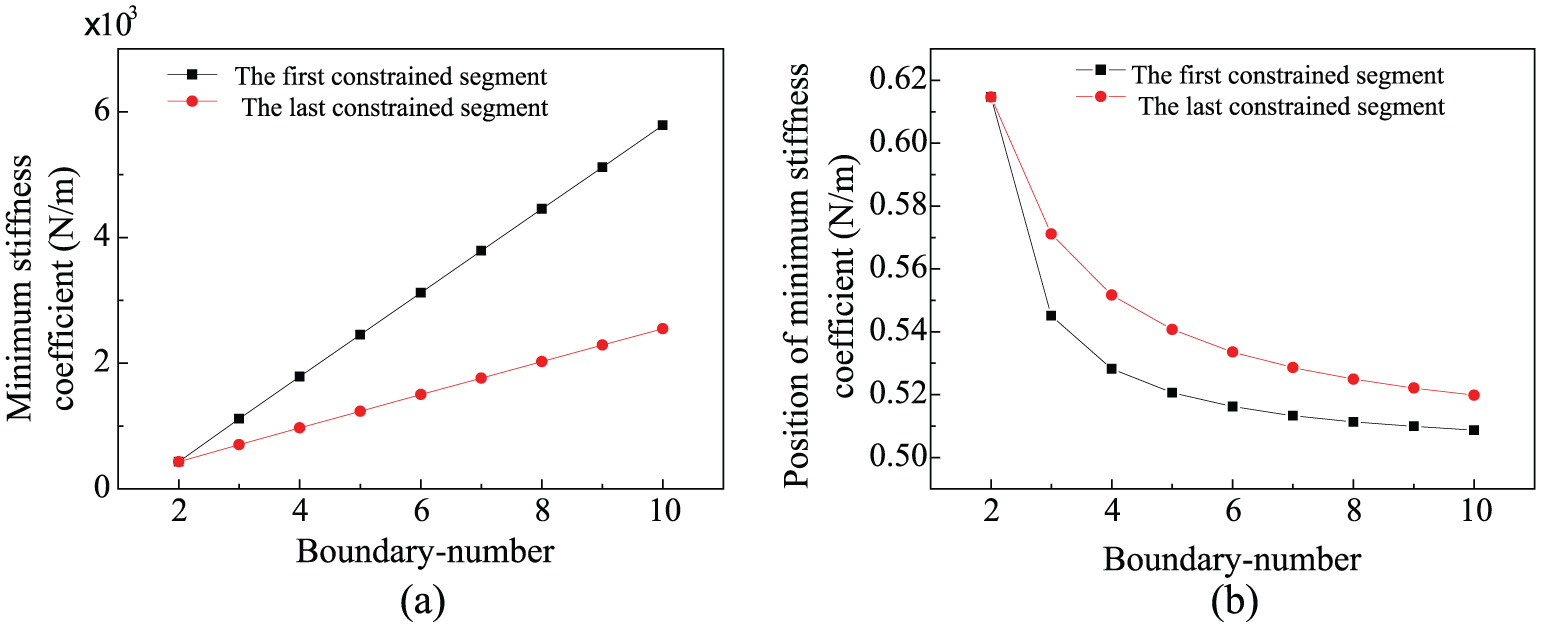
Effects of boundary number on the value and situation of minimum rope stiffness: (a) minimum stiffness varies with boundary increased and (b) position of minimum stiffness varies with boundary increased.
When the boundary constraints are uniformly distributed, the minimum stiffness of the first and last cable segments increase linearly with an increase in the number of boundaries as shown in Figure 7(a), and correspondingly, more boundary constraints lead to the positions of minimum stiffness approaching the middle of the cable segments as Figure 7(b) shows. When the boundary number is more than 4, the increased boundary constraints have small effects on the positions of minimum stiffness.
According to the national standards, the minimum stiffness should be more than or equal to 500 N/m. The minimum top and bottom tensions can be obtained with multiple boundaries based on the above parameters as shown in Figure 8, which shows that the required minimum tensions at top and bottom varied obviously with boundaries increased at beginning. When the number of constraint boundaries is more than 4, the increased boundaries have little effects on the required minimum tensions.

Boundary number effects on minimum tensions.
The deflection characteristics and arrangements of guide cable
In the case of the two arrangements of deflection suppression system, the cable displacement and stiffness characteristics are analyzed with the conveyance moving down and two deflection suppression systems used. And the distances from the constrained positions to the top tensioned position are L1 = 1/3L and L2 = 2/3L. The displacement characteristics and the stiffness characteristics of cable are shown in Figure 9(a) and (b), respectively, with no deflection suppression systems installed. w1(x), k11(x), and k12(x) are curves with cable and deflection system arranged as shown in Figure 3(b), where w1(x) is deflection curve and k11(x) and k12(x) are stiffness curves of west cable and east cable, respectively. w2(x) and k2(x) are curves with cable and deflection system arranged as shown in Figure 3(a), where w2(x) and k2(x) are deflection and stiffness curves, respectively.

Deflection and stiffness characteristics of guide cable: (a) cable deflection with 4 boundaries (W-E arrangement: w1(x), N-S arrangement: w2(x)) and 2 boundaries (w(x)) and (b) cable stiffness with 4 boundaries (W-E arrangement: k11(x) and k12(x), N-S arrangement: k2(x)) and 2 boundaries (k(x)).
Figure 9(a) and (b) shows that the cable displacement obviously decreased and its stiffness significantly increased with two deflection suppression systems installed.
Whether the guide cables are arranged on east–west sides or north–south sides of conveyance, the maximum displacement in each constrained cable segment is increasing gradually from top to bottom. This is because the cable tension at upper constrained position in each cable segment reduced when the conveyance moves down.
As shown in Figure 9(a), the deflection of two cables arranged in east and west is larger than that arranged in south and north. Figure 9(b) shows that when the conveyance moves down, the stiffness of the cable arranged in west is the same as that of two cables arranged in south and north because constrained boundaries of the cables under the two conditions are the same. And the stiffness of the cable arranged in east is the same as the stiffness of two cables with no deflection suppression system installed because both the constrained boundaries of the cables under the two conditions are four. Similarly, when the conveyance moves up, the stiffness of the cable arranged in east is the same as that of two cables arranged in south and north, and the stiffness of the cable arranged in west is the same as the stiffness of two cables with no deflection suppression system installed.
Therefore, the average stiffness of the guide cables arranged on east and west sides of conveyance is smaller than those arranged on south and north sides of conveyance under the condition of multi-boundary constraints. And the guide cable arranged on south and north sides of conveyance is better.
Conclusion
In this article, the equilibrium equation of lateral deflection is established in deep vertical cable-guided system. The analytical expression for the lateral stiffness of guide cables ignoring its bending stiffness under multi-boundary conditions is deduced. And the conclusions are as follows:
The deflection characteristics of the guide cable under two conditions that bending stiffness is considered and ignored are analyzed. And the conclusion is that bending stiffness can be ignored in cable-guided system of 1500 m deep shaft.
With an increase in the top tension, the minimum stiffness of guide cable in each constrained segment increases rapidly at the beginning and later linearly, and its position approaches the middle of two adjacent constrained positions on the cable.
With an increase in boundaries, the minimum stiffness of guide cable in each constrained segment increases linearly and its position approaches the middle of two adjacent constrained positions on the cable.
The increased boundaries in cable-guided systems can reduce the originally required minimum tension. And the minimum top tension of guide cable can be chosen for use according to the number of boundaries.
3. Under the condition of multiple boundaries, the arrangement of guide cable and deflection suppression system in north and south sides of the conveyance is better than that in east and west sides.
Footnotes
Appendix 1
In order to obtain the equation (20), element stiffness matrix
where the corresponding values below the bottom brackets “︸” indicate the number of elements in parentheses and bottom brackets in the following formulas have the same meaning.
where
in which
In order to obtain the equation (24), element stiffness matrices and generalized stiffness matrices at W-E arrangement are shown in equations (31) and (32) according to equation (21), respectively.
where fA1 and fA2 are forces at the top and bottom constrained point in the ith restricted segment on Cable A, respectively. fB1 and fB2 are forces at the top and bottom fixed point on Cable B. In equation (24),
where
In equation (35), subscript k = 0, 1, …, (n + 2)N0 + 1. In equation (25)
Academic Editor: David R Salgado
Declaration of conflicting interests
The author(s) declared no potential conflicts of interest with respect to the research, authorship, and/or publication of this article.
Funding
The author(s) disclosed receipt of the following financial support for the research, authorship, and/or publication of this article: This work was supported by the National Natural Science Foundation of China (51475456), the National Key Basic Research Program of China (2014CB049401), and the Priority Academic Program Development of Jiangsu Higher Education Institutions (PAPD).