



Abstract
The optimization of the igniter position is a critical issue in modern aviation gas turbines since it can help to minimize the amount of energy required for ignition and to guarantee a fast relight in case of flameout. From a numerical perspective, several spark discharges should be simulated for each spark position, to account for different realizations due to time-dependent turbulent motions. Unfortunately, standard simulations are impractical to use for this purpose, due to the need of carrying out several unsteady simulations, leading to a huge associated computational effort. This is why low-order models have been developed, providing an affordable estimation of the local ignition probability, by sacrificing the accuracy and the physical consistency of the prediction. In the present work, a previously developed low-order design model has been implemented in ANSYS Fluent 2019R1® and used to investigate the ignition performance of a single-sector, confined spray flame, where data from laser ignition experiments are available. A non-reactive Large Eddy Simulation, which is validated against experimental data, provides the base flow needed to feed the model. If the tuning parameters of the ignition model are well calibrated, it provides quite good results. In the test case here investigated, it is shown that ignition is possible in the outer recirculation zone and very unlikely elsewhere. Later, a discussion about the effect of the most relevant tuning parameters is carried out. It is shown that the model mostly succeed to identify the area of possible ignition, even if the lack of calibration could lead to a poorer agreement with the experimental data.
Introduction
Altitude relight has always been a critical point in the design of aeronautical combustors. Regulations are issued by the European Union Aviation Safety Agency (EASA) and the Federal Aviation Administration (FAA) about in-flight re-ignition of an engine in the case of flameout: complete restart of the engine should be achieved under several conditions of altitude and airspeed, within a set timeframe or in severe configurations including the emergency descent 1 . Recent design trends, such as the growth of the Bypass Ratio 1 , the use of Lean Direct Injection technology 2 and the interest towards alternative fuels 3 possibly make the situation even more complex. Moreover, a proper design of the combustion chamber accounting for the ignition phase may lead to a better arrangement of the spark plug, leading to increased maintenance intervals, lower energy required and possible reduction of the overall time to re-start the engine. With all that said, the knowledge and the understanding of the ignition process in aero-engine burners are nowadays of paramount importance, also during the early design stages of a new engine or in the improvement of an old one.
In scientific literature, the ignition of aircraft burners or laboratory scale combustors has been often investigated through fully reactive LES4–8. Such approach, although extremely promising, might fail to provide relevant design help due to the large computational effort required, which may be excessive in a stage where the final combustor geometry (and the flow-field accordingly) is not yet defined. Moreover, a single LES of the ignition process can achieve a very detailed representation of a certain ignition event, starting from particular initial conditions, but it fails to provide proper statistical representation. In reality, each ignition event is characterized by a strongly different instantaneous flow field and fuel distribution during spark discharge. It is now worth introducing the so-called ignition probability Pign, which represents the ratio between the number of successful spark events and the overall number of events. Several definitions can then be attributed to successful ignition, but it normally refers to the successful onset of a stable flame within the combustor. Clearly, Pign represents one of the most desired criterion during the design stage along with the time required to complete flame stabilization.
In 9 and 10 an approach based on brute force LES is attempted to compute Pign: the results shown are very promising but the computational effort of 1.5 M CPU hours reported in 10 is still excessive in early design stages, although the proposed approach could be considered for final validation. Recently, an efficient approach based on high-fidelity hot-flow LES and tabulated chemistry has been presented by 11 . A look-up table is generated using a homogeneous reactor for the kernel ignition stage, whereas a flamelet progress variable approach is used for the flame propagation stage. The two different look-up tables are then combined linearly and several LES of the ignition process are performed. The ignition probability is computed as a function of the operating conditions and the kernel characteristics using an uncertainty quantification analysis. In 11 to simulate 803 ignition events approximately 1 M CPU hours have been used, leading to a CPU cost of roughly 1200 hours for a single spark discharge.
If a even lower computational effort is desired, ignition models based on a single simulation (either RANS or LES) of the non-reactive flow field before ignition 12 have been proposed. The common idea behind these models is to provide a very fast estimation of the ignition probability for a particular spark location by introducing relevant assumptions, at the expense of a lower physical consistency. Following the classification reported by 13 two main strategies can be identified: models based on flow properties at the spark position and models based on kernel trajectory.
Regarding the first set, in 14 the I-CRIT-LES model is introduced: it is based on the use of local flow properties coming from several instantaneous solutions of a non-reactive LES of the burner. Starting from a certain time-step with an associated instantaneous flow-field, five consecutive conditions are evaluated for each point under investigation and all of them must be met to give a successful ignition event. These criteria include the flammability of the mixture at the spark time, the survival of the hot gas kernel and the onset of the flame, the growth of the flame due to fuel vaporization, the quenching of the flame near the wall and the upstream propagation in the combustion chamber.
Alternatively, in 15 and 16 a Perfectly Stirred Reactor (PSR) is used to investigate the evolution of the spark generated by a sunken fire igniter in a stratified turbulent flow. First, a air/plasma reaction mechanism is used to describe the plasma kernel evolution without considering fuel (wich considers the absence of fuel close to the wall where the spark is discharged) while a methane/air mechanism is considered for the following kernel evolution stage. Kernel expansion is computed from experiments and the associated increase in mass is included by enlarging the PSR to keep the pressure constant. Despite the promising results presented in14–16, those models do not take into account the possible convection of the hot gas kernel inside the recirculation zone, which is reported to be the main mechanism of ignition in swirling flows. To overcome this issue, trajectory models can be employed, where the attention is focused on the displacement of the hot kernel of gas due to flow convection, rather than the first stages of kernel formation and development.
In 13 a novel trajectory model is presented, where the tracking of the kernel is performed using a presence Probability Density Function (PDF). In the beginning, this PDF is assumed to be Gaussian and it is centred around the sparking position. Mean velocity and fluctuations are retrieved from a non-reactive flow field solution and used to compute the displacement and expansion in time of the presence PDF previously mentioned. The radius of the PDF is also evaluated to take into account the potential quenching and the growth rate of the flame. Finally, a conditioned kernel presence PDF is evaluated and integrated into space and time to obtain the ignition probability. The model has been recently presented, showing a very promising agreement with the experimental data used in the present work.
Another alternative is represented by the SPHINTIR model
17
: it is based on stochastic tracking of Lagrangian particles, called flame particles, that mimic the displacement of the hot kernel by being transported through the computational domain following a Langevin equation. Cells visited by the flame particles are considered ignited and can emit a new flame particle. Moreover, flame quenching is introduced using a criterion based on the Karlovitz number
The Lagrangian Ignition Map using Inverse Time (LIMIT) model has been recently presented in 23 . This model is similar to the SPHINTIR model, except for the time integration which is performed backward in time to obtain the ignition probability. In fact, if in the SPHINTIR model an initial spark location is assumed and the flame evolution is tracked, here a final ignitable region is defined and Lagrangian entities are tracked backward in time to find the successful locations of the spark. As an advantage, all the sparking locations are evaluated in a single run. Moreover, the a priori definition of the final (initial from the LIMIT point of view) ignition region allows to explore only the successful paths, thus avoiding to consider sparking locations that will certainly fail. A rather complex strategy is also implemented to clone or remove particles in order to enhance the model convergence and keep low the computational effort.
In this work, the original SPHINTIR approach presented in 17 has been implemented in ANSYS Fluent 2019R1 ® and used to compute the ignition probability map of a swirled spray burner 24 .
The paper is structured as follows: first of all, a brief description of the SPHINTIR model is provided. Then, the investigated experimental rig is presented as well as the numerical domain employed for the complete non-reactive LES and the ignition probability model. Finally, an exhaustive validation of the approach is performed exploiting several experimental data, followed by a brief sensitivity on some of the user parameters involved in the SPHINTIR model.
The objective of the paper is to evaluate the performance of the SPHINTIR model on this combustor, where detailed experimental data are available to finely validate both the cold-flow simulation used to feed the model and the results in terms of ignition probability. The throughout validation of the cold-flow simulation and the sensitivity analysis to the model constant constitutes the main novelty of this work. In fact, at the best of the author knowledge, the model has been applied to liquid-fuelled combustors only in17,19 where little or no validation was shown before analysing the ignition probability map. In the present work, the reader should be able to better understand the accuracy of the ignition probability model and the impact of its tuning parameters, with respect to the agreement achieved in the simulation used to feed it. Moreover, its implementation in a commercial software represents another important step, which has not been attempted before and could dramatically spread its use in an industrial context.
Ignition probability computation
In the present work, the original version of the SPHINTIR model presented by Neophytou et al. 17 has been implemented in ANSYS Fluent 2019R1 ®. No relevant modifications have been introduced to the model therefore the reader interested in a detailed review of the approach is referred to17,19,21,22. Hereby, only the main features of the model are described to introduce the presented results.
In practical geometries, the main mechanism to obtain a successful ignition is the convection of the spark kernel in the IRZ, that eventually leads to flame stabilization 25 . Because of this, all the phenomena that immediately follow the initial deposition (i.e. the kernel generation phase 12 ) are less important while the following transport of the kernel is assumed to be more relevant.
As anticipated in the introduction, Lagrangian particles called flame particles are employed for this purpose. The tracking of the particles is performed using flow data from a non-reactive simulation, called base solution from now on. To compute the ignition probability, the fraction of the domain visited by the flame particles is considered.
The following steps can be identified (Figure 1):
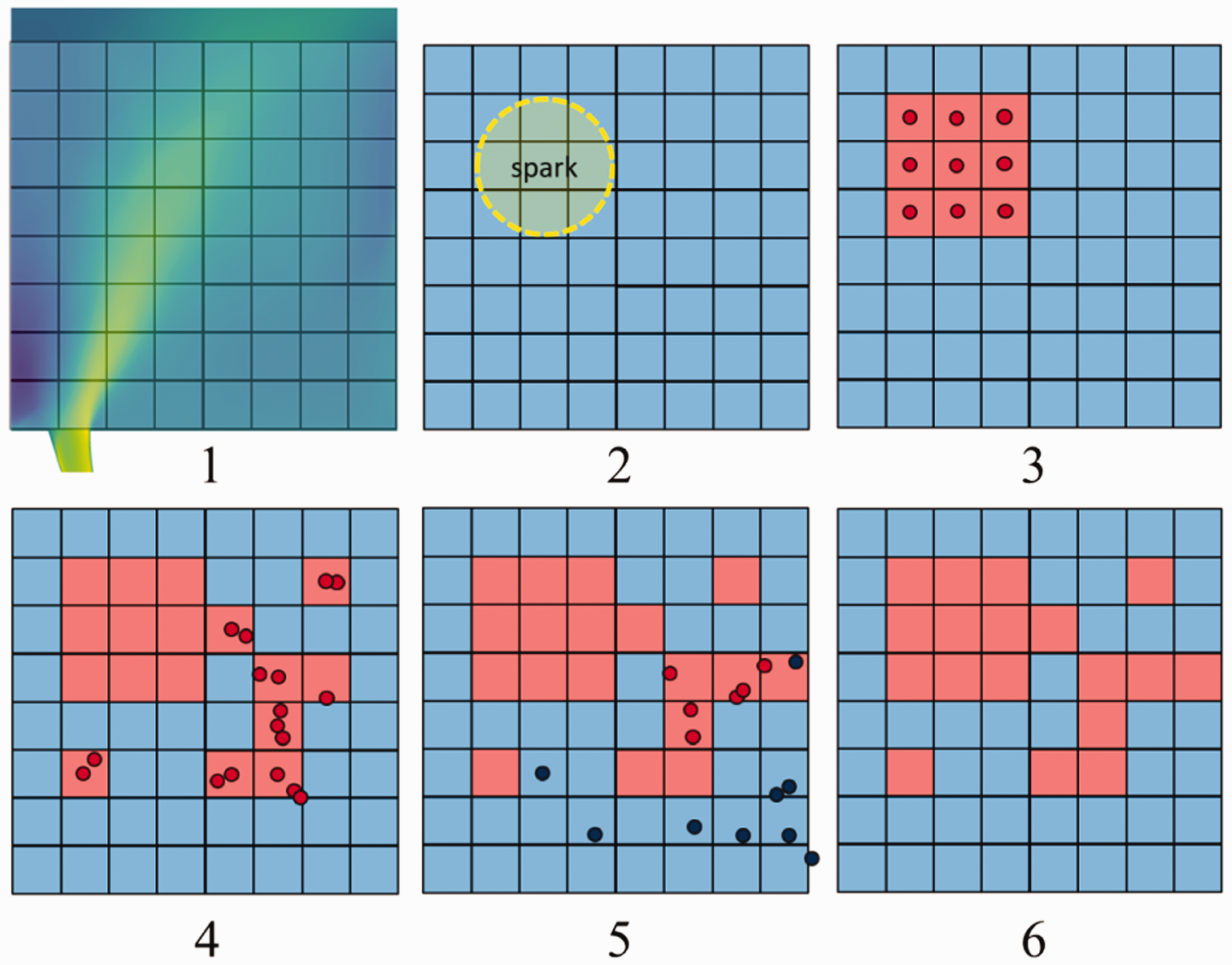
Steps of ignition probability computation.
interpolation of the flow-field: a specific mesh is used to interpolate the data from the base solution and track the flame particles. The variables required by the model include the velocity, the mixture fraction, the SMD and the evaporation rate. At the beginning, all the cells composing the domain are set to unburnt state and they will eventually be ignited during the simulation (burnt state). It is important to mention that a specific mesh can be used, which can represent only a specific region of the domain to reduce the computational effort.
Initialization of the spark volume: a certain spark volume is defined by the user and used to initialize the spark propagation. In this work, an initial spherical shape has been chosen, characterized by a radius rsp. Here the mixture is assumed to be already ignited and the preliminary stages of energy deposition, plasma formation and start of the reaction process are overlooked. It is clear that the amount of energy released by the spark could affect such initial volume, but this relationship is not straightforward as it is probably a complex function of local flow variables. Due to the uncertainty in its evaluation, rsp will be the subject of a sensitivity in the final part of the the present paper. To obtain the local ignition probability, several simulations will be performed using the same position of the spark while, to compute the ignition probability map, several spark locations have to be tested.
Flame particles injection: all the cells that overlap the initial spark volume are set to burnt state. They can now release a new flame particle: velocity and mixture fraction are randomly initialized according to a Gaussian distribution for the velocity and a β-distribution for the mixture fraction (using the mean and the RMS from the base simulation).
Flame particles tracking: particles are tracked inside the domain using a Langevin equation (equation (1)). The variation of velocity in the i direction of the pth particle is given by:

where 5. Particle extinction: at the end of each time step, a criterion based on the Karlovitz number of the particle 6. Final computation of the ignition probability: once that a spark event is completed, the ratio between the burnt cells and the overall number of cells is evaluated, defining the ignition progress factor
where ν is the laminar kinematic viscosity of the mixture and



In this way, the model can take into account the effects of mean and fluctuating velocity on flame propagation, the stochastic effect of turbulence and the local extinction due to high turbulent strain rate 17 .
The implementation in ANSYS Fluent 2019R1 ® has been carried out using User Defined Functions, allowing different spark positions to be run in parallel using a dedicated Python job manager. The main advantages of using a commercial solver are the exploitation of the pre-existing Lagrangian tracking framework and the easier interpolation from the base simulation to the dedicated grid for ignition probability (step-1). It is worth pointing out that the model is built to run as a post-processing tool on the LES field.
Investigated experimental rig
The experimental rig under investigation is the so-called KIAI-CORIA burner, built in the course of the Knowledge for Ignition, Acoustics and Instabilities (KIAI) EC funded project. In this work, the single injector confined test-bench presented in24,29 fuelled with liquid n-heptane has been simulated.
A sketch of the rig is shown in Figure 2. A plenum feeds with preheated air at 416 K the radial swirler (18 channels inclined at 45°), characterized by a swirl number of 0.76. The outlet of the swirler has an inner diameter of 10 mm, while the outer is 20 mm. It discharges the air into a chamber with a square section of 100 × 100 mm2 and a height of 260 mm. A convergent section is also mounted to avoid flow recirculation. Fuel is supplied by a simplex pressure atomizer (Danfoss, 1.46 kg/h,

View of the KIAI-CORIA rig under investigation (adapted from 8 ).
Operating conditions.
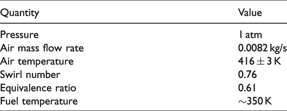
Detailed measurements for the validation of the non-reactive flow field are available. In particular PIV has been carried out to determine the velocity field of the gaseous phase while the velocity and the size of the fuel droplets have been evaluated using a PDA approach. Finally, Toluene-PLIF has been used to measure the equivalence ratio inside the combustion chamber.
A laser-induced spark has been used to ignite the mixture and 132 points have been investigated realizing 30 independent ignition tests. Ignition probability has been computed dividing the number of successful events by the total test number. When a stabilized flame is generated, the ignition event is considered successfull. To make the experiment repeatable, the wall temperature has been monitored and a successive ignition test has been allowed only when it decreases below 387 K. The amount of energy deposited by the laser has been estimated to be around 405 mJ 24 . Recently, in 29 a throughout experimental analysis of the main ignition and extinction mechanisms of this burner has been carried out. In particular, five ignition and five extinction modes have been identified depending on the initial sparking position. The reader interested in additional details about the experimental configuration is addressed to8,24,29.
Numerical details
All the simulations performed within this paper have been carried out with the commercial solver ANSYS Fluent 2019R1 ®. As anticipated, two different domain and setup have been adopted for the two stages of simulation, due to the different requirements of the approaches employed.
Base simulation
A sketch of the numerical domain and prescribed boundary conditions is given in Figure 3. There the spatial coordinates used in the post processing are defined: z-coordinate is employed to indicate the axial distance from the swirler, while the radial distance is marked with r-coordinate (see again Figure 3). The origin of the reference frame is set in the centre of the domain where the liquid injector is mounted.

Numerical domain and grid for base simulation.
The experimental rig has been modelled starting from the air plenum that feeds the combustion chamber up to the convergent discharge section. The fuel atomizer has not been included in the numerical domain because of the employed strategy to handle liquid injection. A constant air mass flow rate has been imposed at the inlet, without applying any additional turbulence generation as most of the instabilities are believed to be generated when the air flows through the swirler. No-slip walls are set at a constant temperature of 387 K as suggested in 8 for the non-reactive case, while constant pressure is prescribed at the outlet.
A fully unstructured mesh containing roughly 10 M cells has been generated, with a minimum size of 0.4 mm inside the swirler and in the jet region, while coarser elements are used elsewhere. LES modelling has been chosen for its superior performance in representing swirling flows compared to RANS. WALE 30 subgrid-scale model has been used. A subsequent verification revealed that the employed mesh allowed to resolve more than the 80% of the turbulence kinetic energy but this is not shown here as the only scope of the base simulation is to provide a realistic flow solution for the second step of the procedure.
Ideal gas behavior was assumed and the mass fraction of gaseous n-heptane has been transported across the domain to retrieve the mixture fraction needed by the ignition probability model.
A pressure-based solver has been used and the PISO algorithm has been employed for pressure-velocity coupling. Spatial discretisation has been treated with Least Squares Cell-Based method for gradients, Second Order for Pressure, Bounded Central Differencing for Momentum and Second-Order Upwind for all the other equations. A Bounded Second-Order Implicit formulation has been used for time. A constant time step of
To track liquid dispersion inside the combustion chamber, a coupled Eulerian-Lagrangian formulation has been adopted to represent the spray dynamics and gas-liquid interactions. Phenomena related to spray primary breakup are overlooked in this approach as the spray is assumed to be diluted. Particles are directly injected over a circle with a given radius of 105 µm at z = 0.0 mm to mimic the injector, following a Rosin-Rammler distribution with a Sauter Mean Diameter of 30 µm31,32, a dispersion parameter q = 2.531,32 and a velocity of 27 m/s derived from correlations. 33 Lagrangian sub-models have been adopted for droplet motion, heating and evaporation, while no secondary breakup has been introduced as it is believed to have a minor impact on the solution due to the low Weber number of the injector. The non-deformable drag law by 34 has been applied to introduce the mutual effect of momentum exchange between the continuous and the dispersed phase. Under the assumption of uniform temperature inside the droplet 35 , evaporation has been modelled as mainly governed by the gradient of fuel vapour concentration at the droplet surface, which constitutes a common hypothesis in the study of dilute sprays. An equilibrium condition has been assumed within the liquid and the fuel vapour over the surface of the droplet so that the vapour partial pressure equals the saturation value at the droplet temperature. Under these assumptions, the evaporation rate has been computed as in 36 using data from 37 for n-heptane thermo-physical properties.
Ignition probability simulation
The specific domain employed for the computation of ignition probability is illustrated in Figure 4. It consists only of a small part of the domain used for the base simulation, including only the regions of flame propagation and stabilization. A large part of the combustion chamber and the whole swirler are not modelled. This choice allows a further reduction of the computational effort required. A uniform hexahedral mesh has been used to track the flame particles, using a constant physical time step of 0.2 ms for a maximum simulated time of 60 ms for a single ignition event.
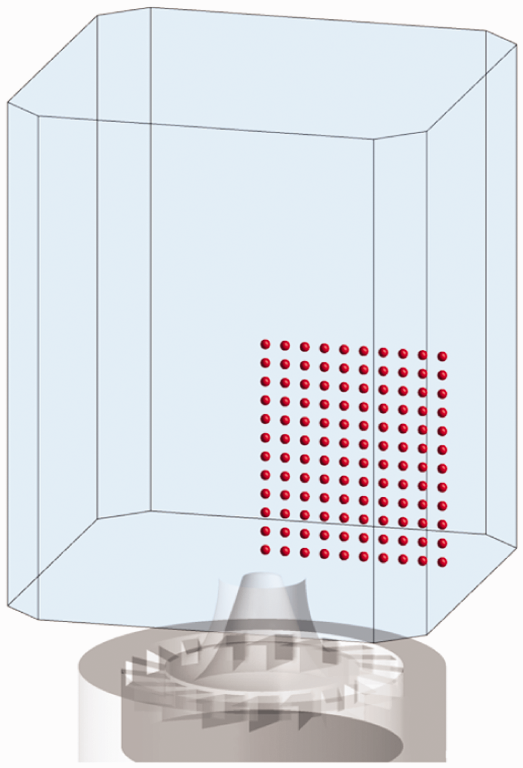
Numerical domain used to compute ignition probability and investigated spark positions.
To obtain a single ignition probability map shown in the next section, 6000 simulations have been carried out: 120 evenly spaced spark locations (marked in Figure 4 with red dots) have been tested for 50 times each one. About 1000 CPU hours have been requested to compute a single ignition probability map on a desktop PC equipped with Intel® Core™ i7-7800X. This represents just a small percentage of the computational resources that would be required to get the same result using reactive simulations.
Results
Base simulation
In this section, an overview of the base solution used to feed the ignition probability model is provided. To asses the quality of such solution, an extensive comparison with experimental data is carried out, considering the main variables used by the SPHINTIR model. The time-averaged and the instantaneous flow field are represented in Figure 5, where three main zones can be identified: the Inner Recirculation Zone (IRZ), the Swirled Jet Zone (SJZ) and the Outer Recirculation Zone (ORZ).

Time-averaged velocity contour from base simulation.
One of the most important inputs for the Lagrangian tracking of the flame particles is the flow velocity before ignition, which is used for both the initialization and the tracking itself (see equation (1)). To assess this data, time-averaged velocity profiles for different z-coordinates are shown in Figure 6 and compared against experiments. The presence of pronounced IRZ and ORZ, characterized by negative components of axial velocity, can be easily pointed out, as expected in a confined swirled combustion chamber. At z = 10 mm high axial velocities can be observed in the SJZ, which eventually fade for higher z-coordinate. The typical structures of the swirling flow are well captured by the CFD computations and a good agreement with the experiments can be pointed out for all the components of velocity.
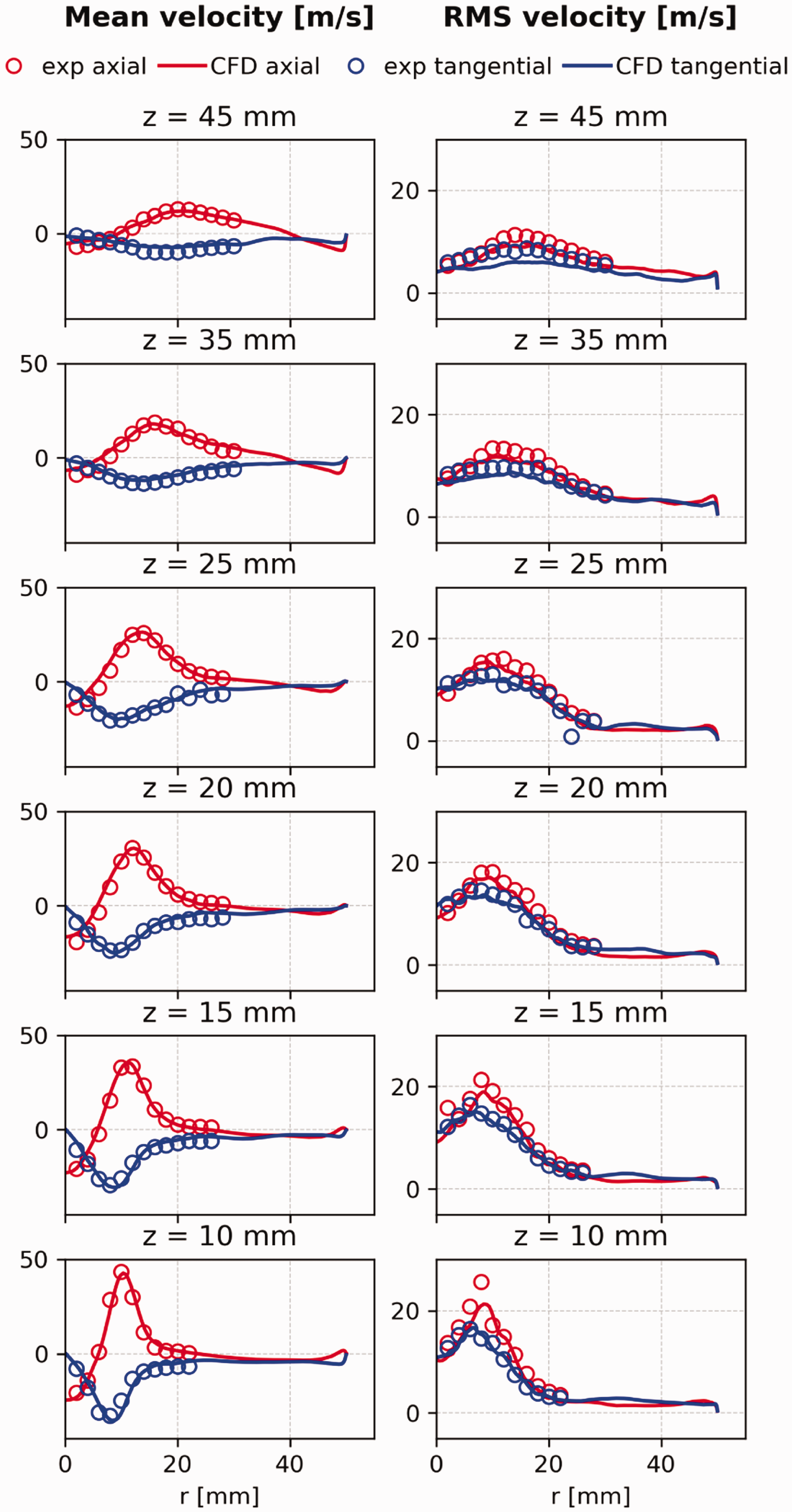
Comparison between numerical and experimental data at different height: CFD axial and tangential velocity against experimental time-average axial and tangential velocity (experimental data from 8 ).
As explained in the modelling section, also the velocity fluctuations are taken into account by the ignition probability model. In fact, in equation (1) a random velocity component is introduced following a random Gaussian distribution. In Figure 6 RMS components of velocity are shown both for CFD and experiments. An overall good agreement can be pointed out, thanks to the use of LES which allows resolving a large part of the turbulent spectrum (i.e. the grid is fine enough to capture the larger turbulent fluctuations). At z = 45 mm the mesh is coarser so the comparison with the experiment is not as good as in upstream stages.
In SPHINTIR, the equivalence ratio of each flame particle (see equation (2)) is used to compute the laminar flame speed employed to calculate the
The comparison between experimental and numerical data in terms of SMD is shown in Figure 7. It should be pointed out that points where SMD calculation was based on less than 5000 drops have been removed from the plot. A proper prediction of the SMD is recovered in the ORZ (large r – coordinate), while a slight under-prediction can be noticed close to the centre-line (r = 0.0 mm). On the one hand, it can be concluded that spray sizing has been correctly imposed at the injection, as suggested by the overall good agreement in terms of mean size in the ORZ and in the SJZ. On the other hand, the poor prediction of the SMD in the IRZ might be due to a poor representation of fuel droplet convection and recirculation caused by the swirling flow. Anyway, as shown in 24 , the amount of droplets experimentally registered in the IRZ is lower than in the rest of the domain and the reported discrepancies are not believed to affect too much the final solution.

Comparison between numerical prediction and experimental data in terms of SMD at different height(experimental data from 8 ).
Finally, Figure 8 shows a comparison in terms of mean equivalence ratio

Equivalence ratio time-averaged field from both base simulation and experiments. The non-reliable region due to the high droplet presence has been blanked (experimental data from 8 ).
In conclusion, despite some issues in the fuel distribution in the IRZ, the base flow simulation provides a good representation of the experiment. This warrants that the application of SPHINTIR will be conclusive with regard to rating the quality of its results.
Ignition probability
In Figure 9(a) comparison between the ignition probability map measured experimentally and computed numerically is shown. The agreement is quite satisfactory, considering that similar trends can be identified in both the experimental and the numerical map. The ignition model strongly underestimates Pign in the SJZ in comparison to the experiments. This is due to the time averaging of the base flow field. The large

Ignition probability map comparison between experiments (left) and CFD (right) using baseline setup (experimental data from 8 ) The white and the black lines demarcate the IRZ and the ORZ respectively.
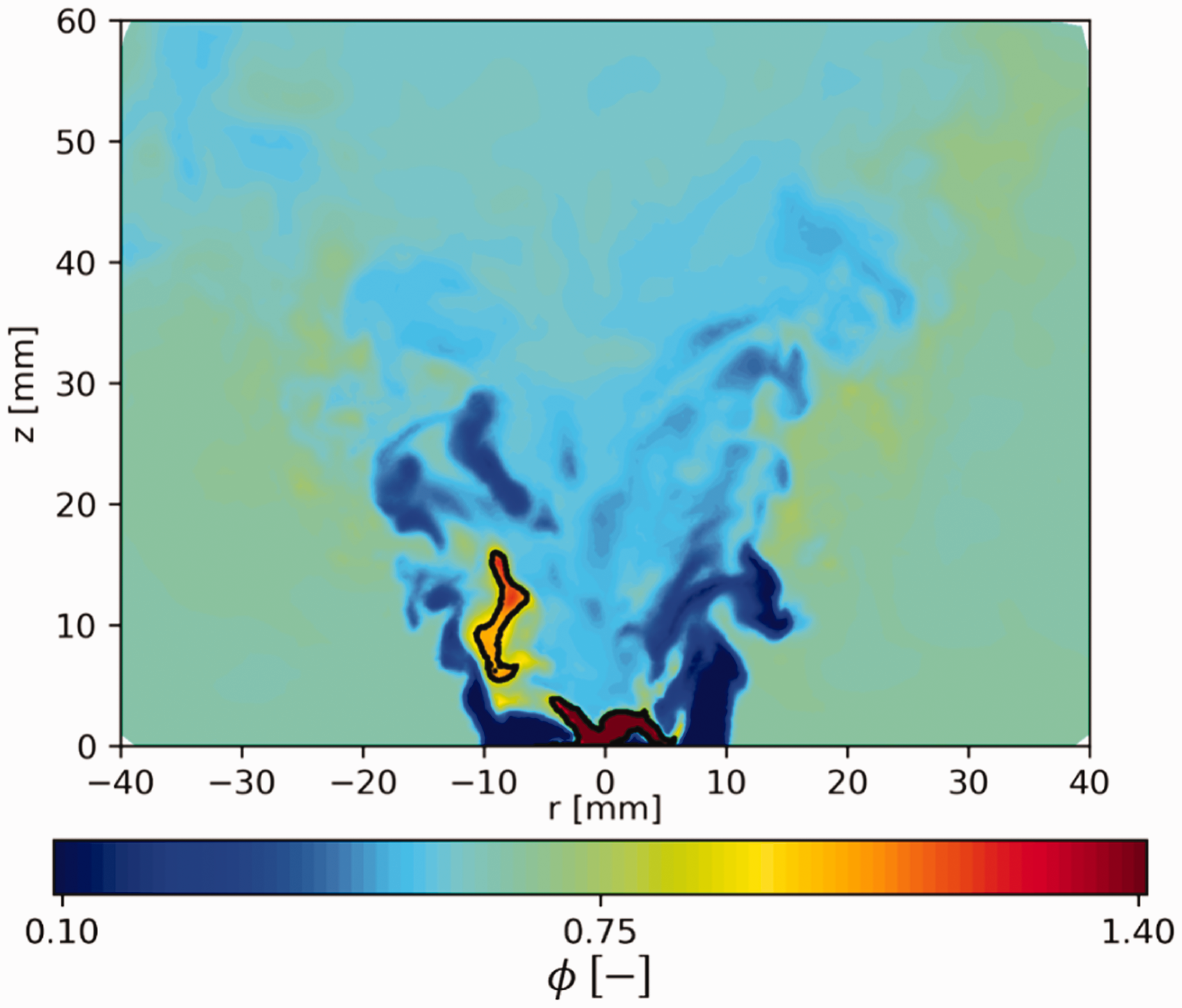
Instantaneous independent snapshots of equivalence ratio with black iso-line at
There is also a small region with
Finally, higher Pign is predicted in the ORZ: despite the absolute value of ignition probability being slightly overestimated by the numerical model, the global shape of the zone is correctly identified, representing sufficient information to potentially improve the design of the combustion chamber. The improvement of the SPHINTIR model is beyond the scope of this work and, based on authors experience, the results shown in Figure 9 already make a useful contribution in the design process.
In this computation, a critical Karlovitz number
Sensitivity to main tuning parameters
In order to obtain the numerical ignition probability map shown in Figure 9, a sensitivity to the main tuning parameters has been performed using the data from base simulations shown in the previous section. For the sake of clarity, the baseline configuration is the one presented above (
Investigated parameters in sensitivity analysis (in bold the data chosen as baseline).

Critical Karlovitz number
Following Neophytou et al.
17
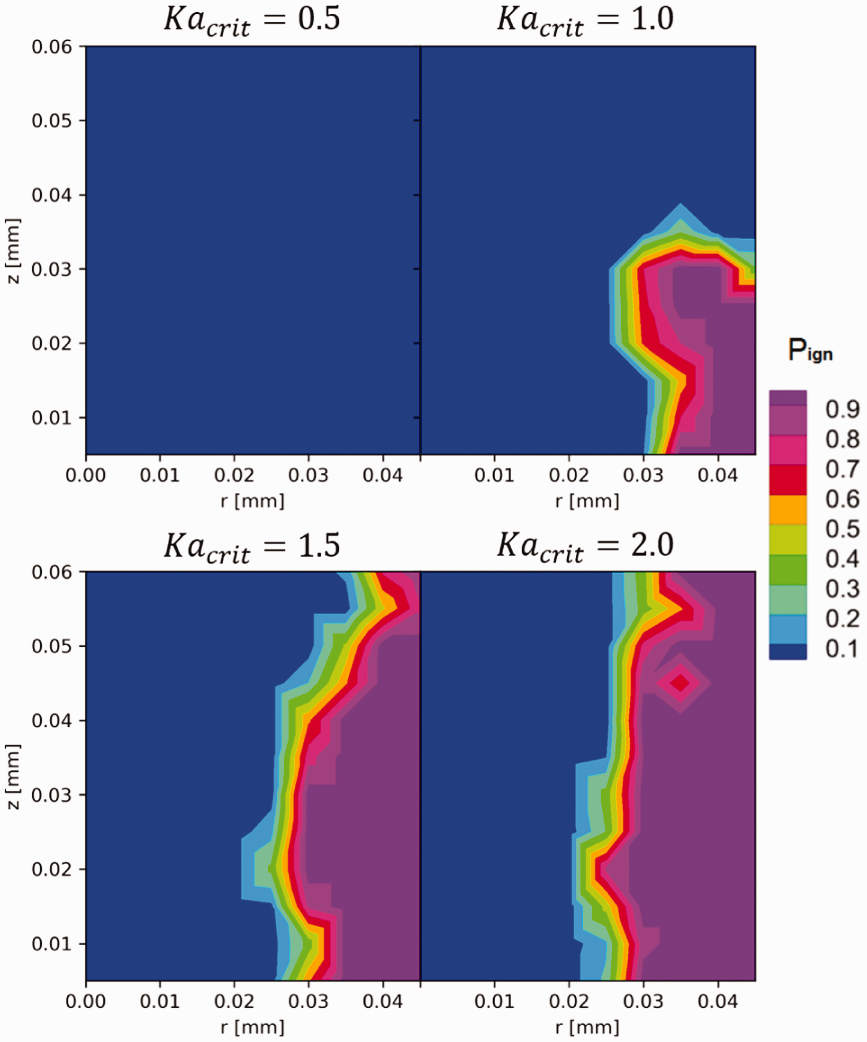
Sensitivity to
In the sensitivity illustrated in Figure 11, an initial value of 1.5 has been tested, verifying that it can properly represent the area with higher ignition probability (note that
The Karlovitz number represents the ratio between the chemical and the turbulent timescales
Critical ignition progress factor
From Figure 12(a) certain effect of the chosen value of

Sensitivity to
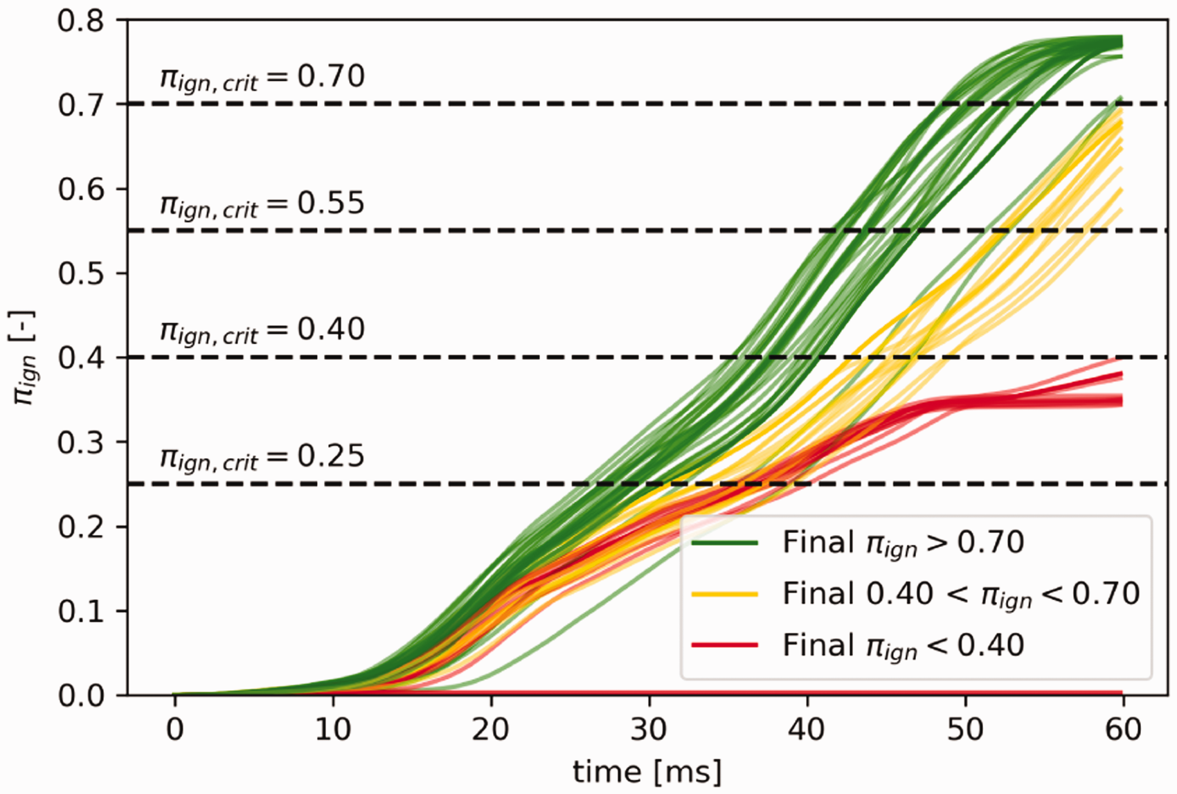
Temporal evolution of πign for r = 35.0 mm and z = 15.0 mm, analysis of different
Mesh sizing
The role of the grid spacing in the SPHINTIR grid has been extensively discussed in 17 , where also some requirements on dx and dt have been introduced. The aim of this section is only to demonstrate the main drawback of the present model: while in CFD a finer grid is usually associated to a more accurate result, this is not the case with the approach under investigation. In Figure 14(a) comparison is shown between two different mesh sizing, showing that better results can be obtained with a coarser mesh. This should not be considered a mistake, but a consequence of the random initialization and tracking of flame particles. As discussed in 17 , by adopting the same initial spark sizing (rsp) a larger number of flame particles is injected, creating more flame particles per unit of volume, i.e. a larger flame particles density. Therefore, the higher the number of particles in the combustor, the higher the number of particles capable of successfully propagate the flame. Therefore, as shown in Figure 15, a reduced mesh sizing leads to many similar ignition events, each one characterized by a similar development in time. On the contrary, a larger grid spacing provides a random development of the initial hot gas kernel.
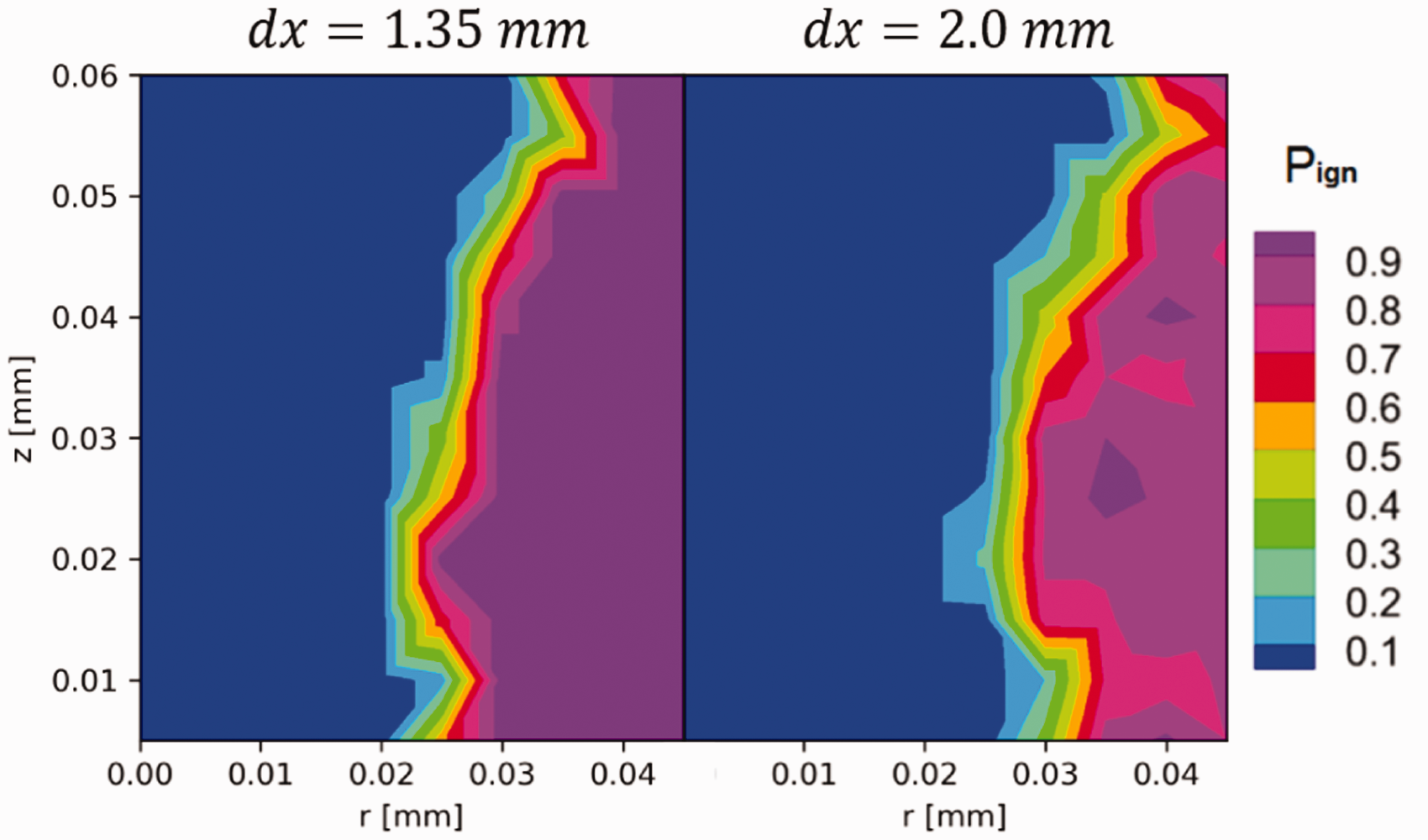
Sensitivity to dx.
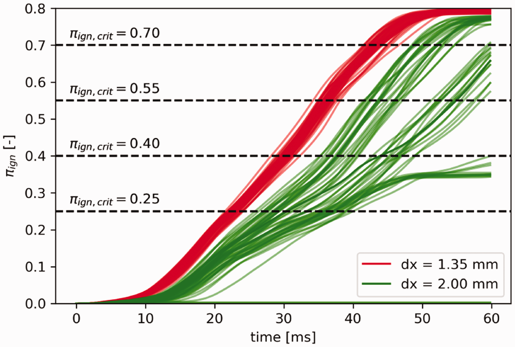
Temporal evolution of πign for r = 35.0 mm and z = 15.0 mm, analysis of different dx.
It would probably be possible to relate the mesh sizing to the amount of energy transported by each flame particle. At the present day, particles have no energy content and all of them have the same chance of survival, irrespective of their number. As already seen, the higher the number of particles, the higher the ignition probability. To overcome this issue, it would be possible to relate the grid sizing (and therefore the number of particles tracked) to the amount of energy released by the spark and later by the progress of the combustion. This amount of energy should also be used to evaluate the extinction criterion.
Spark radius
Experimentally, a nominal spark size of approximately
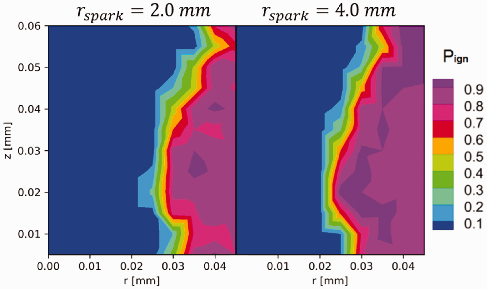
Sensitivity to rsp.
Also in this case, to overcome this issue an energy criterion could be proposed, in order to distribute the same amount of energy deposited by the spark over a larger number of flame particles. At the best of the author knowledge, this approach has not been attempted so far.
Conclusions
In the present work, an existing ignition probability model has been assessed employing detailed experimental data from a swirled spray flame. Like many other numerical models dedicated to ignition probability, non-reactive flow-field data are needed to feed the model: in this case, a LES simulation has been used which was validated against experimental data.
In particular most of the velocity variables needed by the ignition model show very good agreement in terms of mean and RMS fields. The predicted SMD compares well with the measurement in the ORZ while larger deviations are seen in the IRZ.
On this basis, the implemented model has been applied: a fair agreement is obtained with experimental ignition probability map. A very low ignition probability is predicted on the axis of the chamber, due to a relatively low equivalence ratio. A higher ignition probability is expected in the ORZ because of the slightly richer mixture there. A steeper gradient of ignition probability is computed in the SJZ. This is probably related to the time-average frame of the ignition model that cannot account for the intermittent presence of fuel rich pockets which would be ignitable in spite of the large velocity fluctuations.
To analyze the robustness of the ignition model a sensitivity study of the free model parameters was conducted. It showed that the
To conclude, it can be stated that the presented approach represent a proper tool to speed up the design process of a new combustion chamber, considering in particular the low computational effort required to simulate several spark events. Unluckily, the reliability of the results is strongly influenced by the need of tuning some of the parameters involved, which here has been shown through a careful sensitivity in the last section. This currently relies on the availability of experimental data or more accurate simulations, but future work could be addressed to reduce the impact of these unknown variables on the provided solution.
Footnotes
Acknowledgements
Prof. Bruno Renou is kindly acknowledged for providing the experimental data and for the many useful advice. Thanks are also due to Prof. F.X. Demoulin and Dr. Stefano Puggelli for the important suggestions in setting up liquid injection while Dr. Ruud Eggels is acknowledged for the useful discussion about ignition probability modelling. Moreover, we would also like to express our gratitude to GE Avio Aero for the support received for this work. Finally, the authors wish to gratefully acknowledge SOPRANO (SOot Processes and Radiation in Aeronautical inNOvative combustors) Consortium for the kind permission of publishing the results herein.
Declaration of Conflicting Interests
The author(s) declared no potential conflicts of interest with respect to the research, authorship, and/or publication of this article.
Funding
The author(s) disclosed receipt of the following financial support for the research, authorship, and/or publication of this article: This project has received funding from the European Union’s Horizon 2020 research and innovation programme under Grant Agreement No. 690724.
