




Abstract
Thermo-acoustic instabilities are mainly formed due to in-phase superposition of non-uniform heat release and pressure variation in the combustors of gas turbines, rocket engines and other acoustically confined spaces. These instabilities not only damage the structural system but also reduce its combustion efficiency and heat transfer rate. Hence suppression of thermo-acoustic instabilities is a prominent requirement for stable and safe heat generation in the combustors. In this work, the Helmholtz resonator has been used to suppress the instability. The efficacy of the resonator has been further increased by the addition of absorptive material to it. This work concentrates on inspecting the influence of cavity volume, neck length and neck diameter of the Helmholtz Resonator and the thickness of the absorptive material in the damping process of thermo-acoustic instabilities. The experimentation was carried out for various combinations of resonator cavity volume, neck diameter and neck length, and the best combination was found to be 6 mm neck diameter with 20 mm neck length at 60% volume which provided an acoustic damping of around 30 dB. Further, it was noticed that the addition of absorptive material is effective at lower volumes of Helmholtz resonator, and with an increase in thickness of absorptive material beyond a certain limit, the damping ability of the resonator reduces.
Keywords
Introduction
Thermo-acoustic instabilities are a result of combination of pressure fluctuations and unsteady heat release.1–3 This instability is usually observed in combustion systems like jet engines, rocket engines, ramjets, etc. If such instabilities are not checked within time they may lead to loss of combustion efficiency as well as catastrophic structural failure.4–6 There are two methods to control the instabilities namely, active and passive methods. Active methods deal with suppression of instability with the use of external energy sources incorporating techniques like air injection,7,8 phase shift, use of loudspeakers, etc. 9 While passive method utilizes passive elements like Helmholtz resonator, perforated liners10,11 baffles, domestic heating system, 12 etc. To study these instabilities on research level, there is a need for creating this phenomenon in its simplest form. A 1D combustor model called Rijke tube is used to create these instabilities. Rijke tube creates the same acoustic environment condition as present in an actual one-dimensional combustor.13–15
Both active and passive methods have their own advantages and disadvantages. Passive methods generally have an edge over active methods due to no energy requirement and simple construction. Out of all passive methods, Helmholtz Resonator has been widely used and researched.16–22 Depending upon its shape and size a Helmholtz resonator can provide different amounts of damping. Helmholtz resonators can be subjected to a lot of modification to dampen the instabilities. Matveev 23 used porous inserts to enhance the damping for a range of frequencies rather than a single-point frequency. Wu et al. 24 experimented with an array of Helmholtz resonators. Bedout 25 used a tuneable Helmholtz resonator with feedback. Cabral et al. 26 presented a model of a Helmholtz resonator with a multi-perforated plate. Surendran and Heckl 27 suggested an alternative use of heat exchangers to control thermo-acoustic instabilities as a passive technique. Jamieson et al. 28 suggested that adjoint-based methods are capable of providing a cheap and efficient tool for developing optimal control strategies for more complex thermos-acoustic systems. The use of a sound-absorptive material in the resonator may further enhance the magnitude of damping. Selamet et al. 29 modified the Helmholtz Resonator using absorbing material lined along the curvature of the resonator. Porous material has been previously used independently or with a Helmholtz resonator.
This research studies the effect of varying the dimensional parameters of the resonator and the effect of absorptive material on damping. The purpose of the research work is to compare the performance of a Helmholtz resonator of same base cavity volume when it is fitted with neck pieces of different diameters and lengths. Besides, the effect of use of porous medium in a Helmholtz resonator has also been explored. In order to study the effects of neck lengths and neck diameters a series of experiments have been carried out with different combinations of neck lengths and neck diameters. Three neck pieces of diameters 4, 5 and 6 mm have been used. There are three neck pieces of lengths 10, 20 and 30 mm of the same diameter. Altogether there are nine neck pieces which facilitate all possible combinations of neck lengths and neck diameters of the selected dimensions. To study the effects of porous material on the damping capacity, foam pieces of thickness 10, 20 and 30 mm have been used as porous insert in the Helmholtz resonator and their performance has been compared based on the suppression of sound pressure level (dB) created due to thermo-acoustics.
Experimental setup
A horizontal Rijke tube representing a unidirectional combustor of length 800 mm and inner diameter of 80 mm was used for experimentation. Holes were drilled on this tube at a distance of one-quarter of the length from both ends to place the Helmholtz Resonator which was based on the position of anti-node points. A hole was also made to accommodate a pressure transducer to measure acoustic pressure inside the Rijke Tube. A RS 395-257 ultra-low differential pressure transducer was used for the measurement of pressure. The sensitivity of the RS 395-257 ultra-low differential Pressure Transducer is Vo = 1 Volt at 0 psig (Pascal per Square Inch Gauge) and 6 Volt at 1 psig (Pascal per Square Inch Gauge). The transducer was interfaced with NI-DAQ through LabVIEW software to record the values. For the heat source, a ceramic burner was used, which was connected to the outlet pipe of the pre-mixer. The function of the pre-mixer is to prepare a homogeneous mixture of air and fuel.
The air-to-fuel ratio was maintained using air and fuel rotameters. The fuel was supplied from an LPG cylinder while the air was supplied from an air compressor. The air from the compressor was fed to a moisture separator and then to an air dryer to ensure the supply of moisture-free content. The schematic layout of the experimental setup is shown in Figure 1. Figure 2 shows the detailed view of a Rijke Tube along with burner and pressure taps.

Schematic diagram of experimental setup.
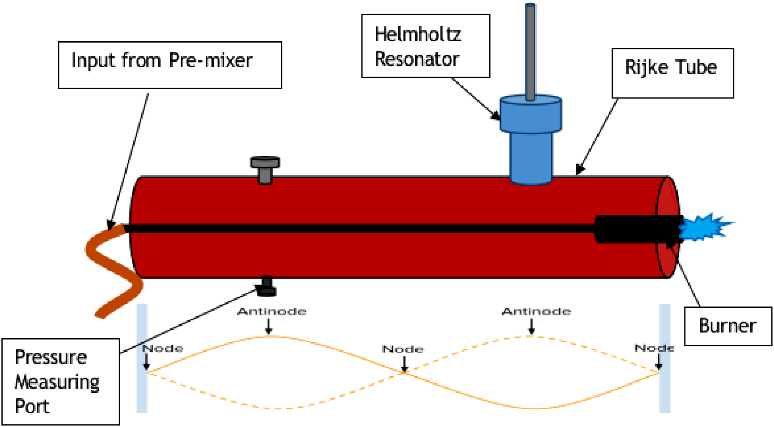
Detailed view of a Rijke Tube along with burner and pressure taps.
At first, the theoretical frequencies of the thermo-acoustic instabilities were calculated using the standing wave equation
25
which is as follows:

If Lactual is the actual length of the tube then the effective length of the tube is given by
Leff = Lactual + end correction.
End correction = 0.3×Internal diameter of the tube (for each end)
Therefore Leff = Lactual + 0.6 × Internal diameter of the tube (taking the effect of end correction on both the ends)
The study was carried out for fixed burner position x/L= 0.25 and air-to-fuel ratio leaner than the stoichiometric value. On the basis of the performed experiments, it was concluded that the Rijke tube produced a second mode of thermo-acoustic instability. The aim of this study is to find the effect of different parameters of resonators on the thermo-acoustic instability and to assess the performance of variable volume resonator for different neck lengths and neck diameters. The resonator was designed for the frequency obtained using equation (2).
25

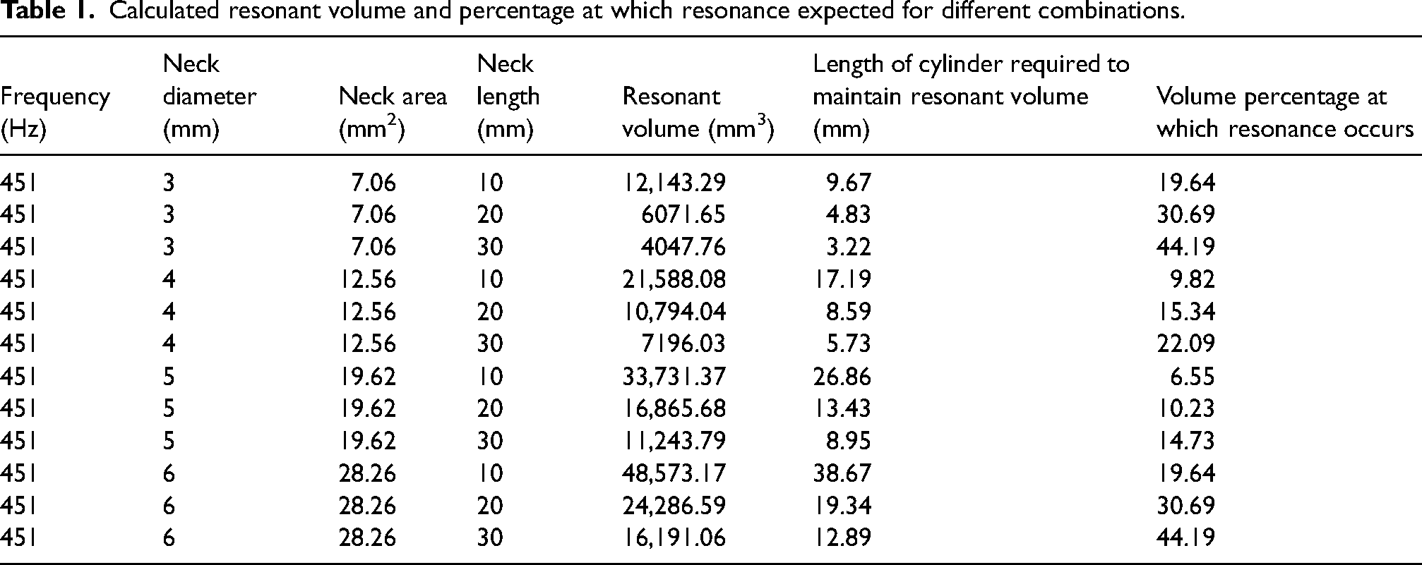
Since the objective of this study is to check the influence of volume, neck diameter and neck length of the resonator on the instabilities, the arrangement for altering the dimensional parameters was taken into consideration while designing it. The required resonant volume is calculated for different combinations of neck length and neck diameters using equations 1 and 2. The corresponding data is presented in Table 1. The base area of the Helmholtz cavity is 1256.64 mm2 corresponding to 40 mm internal diameter. The volume was changed by changing the free length using a piston. The maximum length was kept as 65 mm to adapt the damping of all modes. The schematic model of the resonator is shown in Figure 3. The Helmholtz Resonator was manufactured using 3D printing with PLA as the base material. Neck extensions made of steel were used to change the neck length as shown in Figure 4.
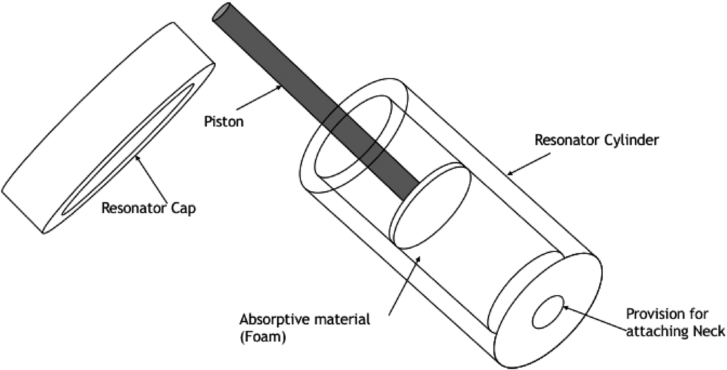
Schematic model of the Helmholtz Resonator.

Fabricated Helmholtz resonator.
Calculated resonant volume and percentage at which resonance expected for different combinations.
For the experimentation, the pressure transducer was set for an excitation voltage of 8 V. The pressure transducer was interfaced with computer using data acquisition system (Ni-DAQ) and LabVIEW software. In this LabVIEW software, virtual instrument block diagram and front panel were made to provide the output of raw signal and FFT (Fast Fourier Transformation). FFT was used to convert raw data (time domain signal) into frequency domain. From frequency plot, the occurrence of second mode was concluded and hence all the experiments were conducted for the second mode. Figure 5 shows the obtained raw signal for second mode of thermo-acoustic instability. The same data was processed through FFT to get the frequency spectra. Background noise was obtained and corresponding frequency plot can be obtained to characterize thermo-acoustic instability. Figure 6 shows the combined frequency spectra for second mode of instabilities and background noise. It shows a peak sound pressure level of 102.45 dB at 451.66Hz. The magnitude of damping is calculated in terms of reduction in sound pressure level measured in decibel (dB). The data is initially acquired in the form of voltage with the help of pressure transducer which is converted to equivalent pressure with the help of conversion factor obtained from the calibration of the pressure transducer. It is finally concerted into sound pressure level (dB) with the help of a suitable relation taking 20 micro Pascals as the reference pressure for audible range. The series of equations involved are given below.


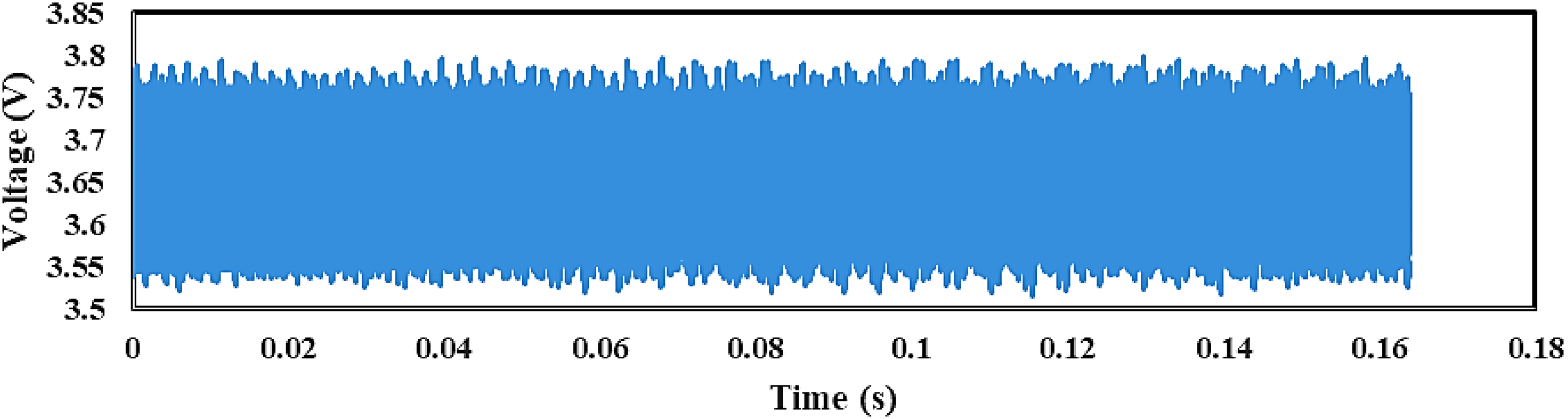
Raw signal in time domain.
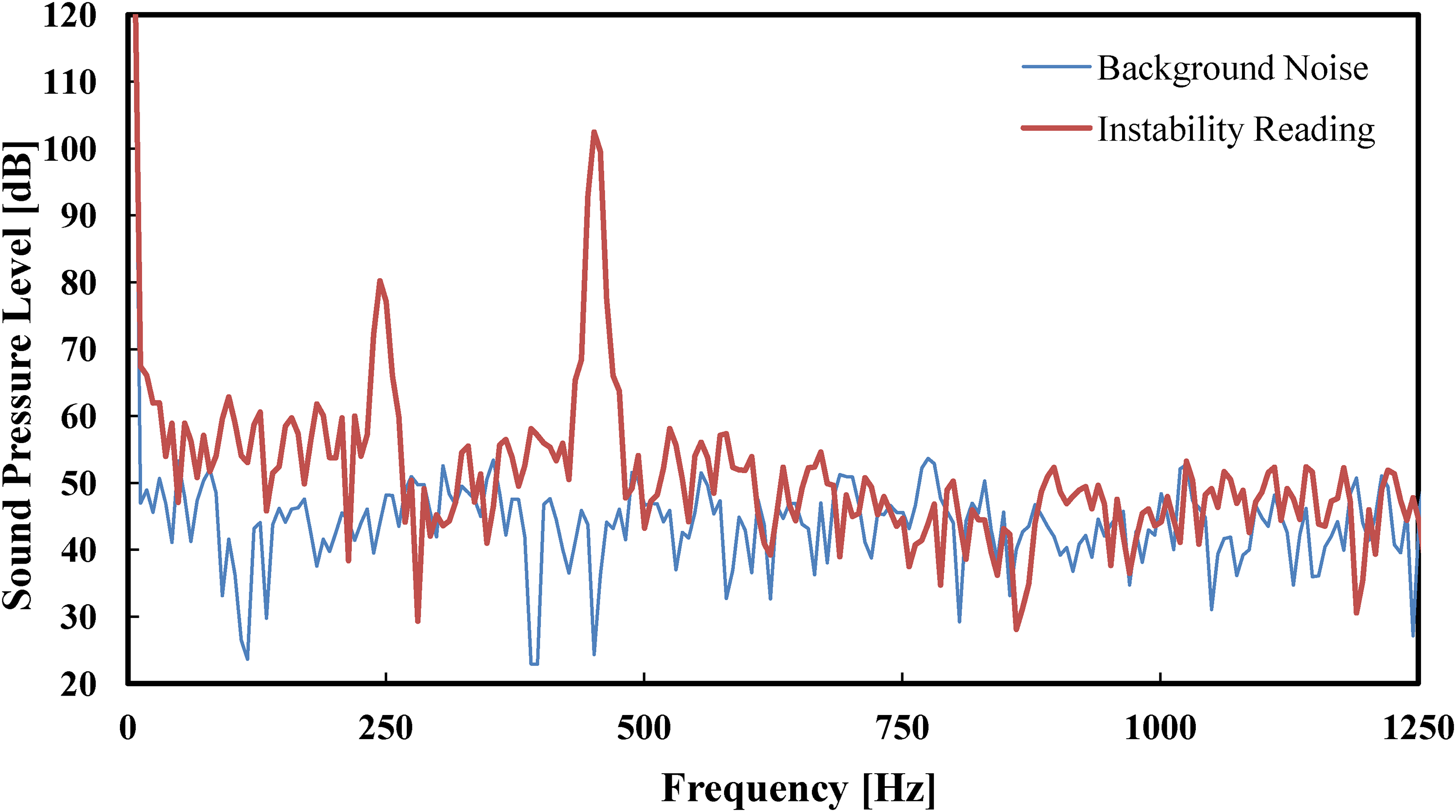
Instability and background noise.
For achieving the aim of this study, the entire volume of the Helmholtz resonator was divided into 10 parts. A scale indicating 10% to 100% of the volume was graduated for carrying out the experiments. A total of 90 readings were taken for the combination at different resonator cavity volumes with neck lengths of 10, 20 and 30 mm and neck diameters of 4, 5 and 6 mm. Absorptive material of varying thickness was added to the piston of the Helmholtz Resonator to inspect its effect on damping.
Effect of varying dimensional parameters of Helmholtz resonator
The comprehensive graphs are shown in Figure 7. Readings were taken for different combinations of neck lengths (10, 20 and 30 mm) and neck diameters (4, 5 and 6 mm) at different resonator cavity volumes ranging from 10% to 100% of the total volume.

Variation of damping at different volumes and different neck lengths with neck diameter of (a) 4, (b) 5, (c) 6 mm.
On comparing the subsequent graphs for 4, 5 and 6 mm neck diameters, it is observed that the magnitude of suppression increases with an increase in neck diameter which suggests that larger diameters offer higher damping. This effect has been observed because of the increase in the acoustic dissipation near the neck wall with an increase in diameter. Moreover, the increase in the neck diameter increases the overall cavity volume which increases the acoustic stiffness and hence better attenuation of the thermo-acoustic instability is achieved.
From Figure 7, it can be visualized that damping of nearly 30 dB was offered by the combination of 6 mm neck diameter and 20 mm neck length at around 30% of the volume. Whereas for 4 and 5 mm neck diameters, a damping of 20 dB was observed at around 40% of the volume. In case of 4 and 6 mm neck diameters, the highest level of damping is observed for 20 mm neck length, while for 5 mm neck diameter, 10 and 20 mm neck lengths offer almost the same amount of damping. Hence, neck length of 20 mm has been found to be the most effective. The damping has been found to be more effective from 30% to 40% of the total resonator volume. Cavity volumes above 60% do not offer any significant damping and thus are inefficient.
The first neck attachment was selected as having 4 mm neck diameter and 10 mm neck length. The position of the piston is maintained such that the effective volume remains constant after addition of the absorptive material. Figure 8 shows the effect of addition of absorptive material to Helmholtz resonator of 4 mm neck diameter and 10 mm neck length.
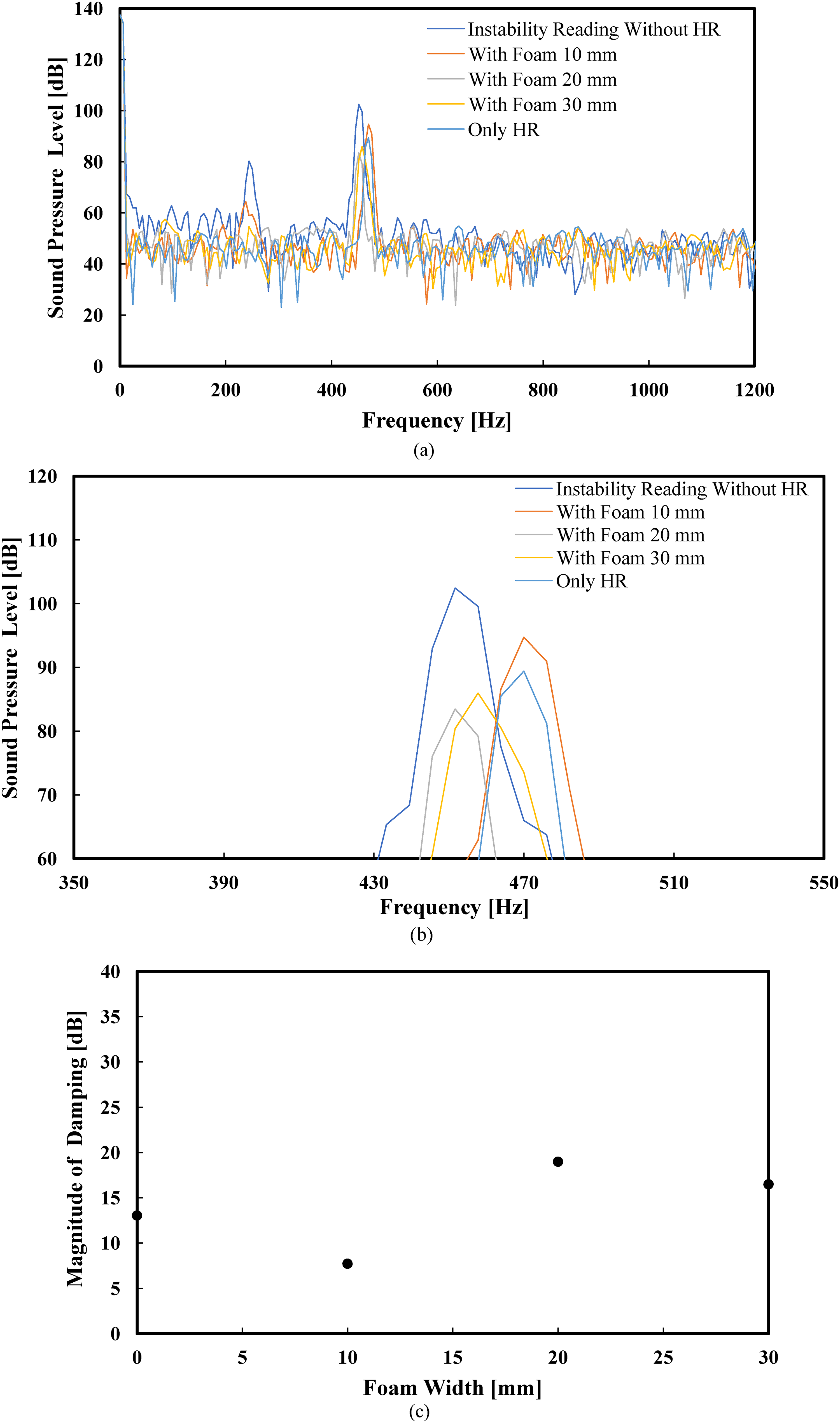
Effect of addition of absorptive material to HR of 4 mm neck diameter and 10 mm neck length (a) frequency spectra, (b) magnified view of the frequency spectra focused on the maximum values of sound pressure levels, (c) variation of damping with foam width.
It is seen from the graph that 10 mm of foam material actually reduces the damping capacity instead of increasing it. The addition of 20 mm of foam is the minimum requirement for establishing further damping in case of this combination.
Figure 9 shows the effect of addition of absorptive material to Helmholtz resonator of 6 mm neck diameter and 20 mm neck length. The next neck attachment was selected as having 6 mm neck diameter and 20 mm neck length. Since this combination damped the system by almost 30 dB, an additional layer of foam was added to check if there can be further damping possible. The volume of cavity was maintained constant by judiciously maintaining the position of the piston.
For the 6 mm neck diameter and 20 mm neck length combination, the graph clearly indicates that there is no effect of 10 mm thick foam whereas the addition of further foam actually decreases the damping capacity.
The resonance volume for 4 mm neck diameter was lower than the resonance volume for 6 mm neck diameter. Also, there was a significant improvement for 4 mm neck diameter while there was a decrease in damping for 6 mm neck diameter. Thus absorptive material is effective at lower volumes of Helmholtz resonator.
In this study, the damping capacity of a Helmholtz resonator at different combinations of cavity volume, neck diameter and neck lengths have been examined by creating a thermal environment using a burner in a Rijke tube which includes the interaction of thermal waves and acoustic pressure fields. It has been found that the effective cavity of the resonator plays a crucial role in acoustic dissipation and subsequent suppression of the instability. Based on theoretical calculation resonant volume requirement decreases with increase in neck length, whereas resonant volume requirement increases with increase in neck diameter. For the low frequencies of interest, the porous material will modify the boundary condition at the bottom wall of the resonator and this will change the resonant frequency of the system. Experiments have been conducted to identify different modes of the thermo-acoustic instability in the Rijke tube. Once the unstable mode of specific frequency was identified, the damping capacity of the Helmholtz resonator was studied at different combinations of neck diameters and neck lengths. It has been observed that as the neck diameter increases the magnitude of damping increases resulting in a reduction in the sound pressure levels. This is because of higher acoustic dissipation at the neck wall with increase in the neck diameter. Besides the effective volume of the cavity increases with increase in neck diameter which helps in suppressing the instability. In case of neck length, the damping capacity has been found to increase with the increase in neck length, which is due to an increase in the acoustic stiffness. However, at higher neck lengths the damping capacity decreases over a certain length. The maximum damping was achieved at a neck diameter of 20 mm. Also, it has been observed that the lower volumes, that is, from 30% to 40% of the total resonator cavity volume, are efficient dampers while higher volumes are not much effective. The best damping of around 30 dB has been achieved at 6 mm neck diameter and 20 mm neck length which is a significant reduction in the instability.
Further, in this study, it has been observed that addition of 10 mm of foam material reduces the damping capacity which is contrary to the usual belief that addition of absorptive material should increase the damping capability of the resonator. Further addition of 20 mm of foam enhances the damping capability of the resonator. It has also been observed that 20 mm of foam is the minimum requirement for establishing further damping in case of 4 mm neck diameter and 10 mm neck length combination. For the combination of 6 mm neck diameter and 20 mm neck length, addition of 20 mm thick foam damped the system by almost 30 dB, but increasing the foam thickness beyond 20 mm actually decreases the damping capacity. Porous sound absorption materials consist of cavities which allow the sound waves entering the materials. Sound energy is dissipated by thermal loss caused by the friction of air molecules with the pore walls, and viscous loss as a result of viscosity of airflow within the materials. The addition of 10 mm thick foam does not produce enough surface for the thermal-viscous losses resulting in less suppression of acoustic waves. As the thickness of the porous material is increased to 20 mm the surface area available for thermal and viscous losses within the porous material increases which results in better suppression of thermo-acoustic instability. Further increase in porous material beyond 20 mm reduces the free cavity volume of the resonator which reduces the thermal-viscous losses resulting as the outcome of acoustic waves oscillating within the resonator cavity.
The resonance volume for 4 mm neck diameter was lower than the resonance volume for 6 mm neck diameter. Also, there was a significant improvement for 4 mm neck diameter while there was a decrease in damping for 6 mm neck diameter. It was also observed that absorptive material is effective at lower volumes of Helmholtz resonator.
The resonance frequency is identical in both cases (cavity volume of 0.3 Vmax and the neck length of 20 mm, as well as the cavity volume of 0.6Vmax and the neck length of 10 mm) and amounts to 451.51 Hz, which is very close to the measured oscillation frequency (451.66 Hz). This is a necessary condition in order to increase the magnitude of oscillation of the air mass in the neck of the resonator. The volume of the designed resonators and neck pieces of different dimensions are selected in such a way so that the frequency of the resonator matches with the frequency of the oscillating air in the Rijke tube so that maximum amount of energy can be dissipated as thermal viscous losses.
For the sake of simplicity, an experimental setup in the form of a Rijke tube has been used for our study, the results obtained would be useful for design and selection of optimum neck length and neck diameter along with proper volume of the Helmholtz resonator in real industrial or gas turbine combustors in order to achieve maximum suppression of thermo-acoustic instability.
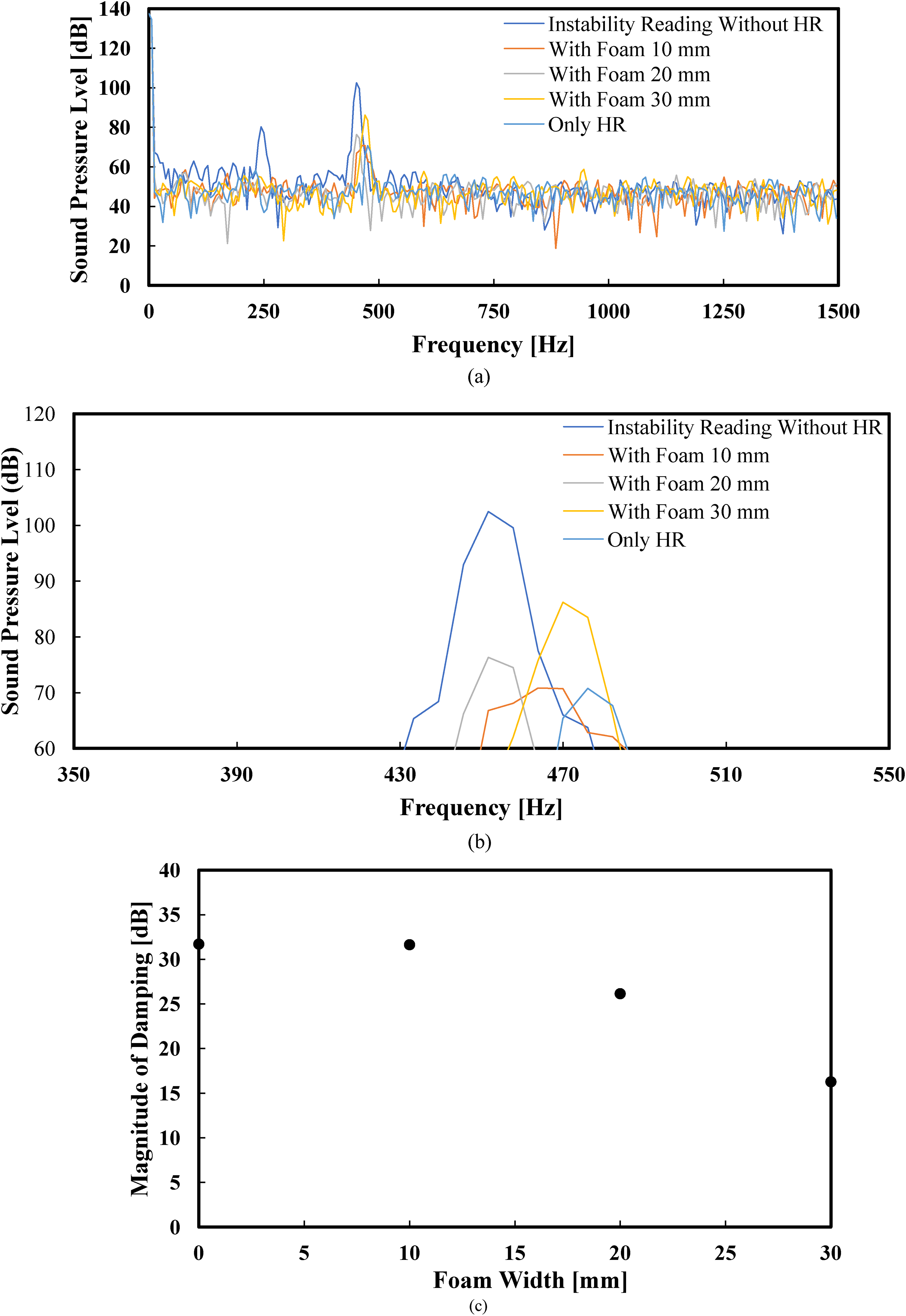
Effect of addition of absorptive material to HR of 6 mm neck diameter and 20 mm neck length (a) frequency spectra, (b) magnified view of the frequency spectra focused on the maximum values of sound pressure levels, (c) variation of damping with foam width.
Footnotes
Declaration of conflicting interests
The author(s) declared no potential conflicts of interest with respect to the research, authorship, and/or publication of this article.
Funding
The author(s) received no financial support for the research, authorship, and/or publication of this article.
