



Abstract
Combustion of steam-diluted fuels offers low emissions and fuel flexibility, but thermoacoustic instabilities remain a challenge. Burner acoustics play a crucial role in the prediction and control of such instabilities. This study reports an experimental investigation of the acoustic characteristics of a dual-swirl burner integrated in a humid combustor. In contrast to conventional two-port burners, this burner features three ports of acoustic flux: Two non-stiff inlets corresponding to air and steam-fuel mixture, and one outlet. A full characterisation of such a three-port is demanding for practical burners. Based on the assumption of acoustic compactness, a Reduced-order Model is proposed for the three-port Burner Transfer Matrix (BTM). The model treats the three-port as a combination of two compact two-ports with no interaction between the two inlets. It allows obtaining the reduced three-port BTM with only two linearly independent acoustic states, as is done for a two-port, but with additional microphones for the third port. First, the two-port characteristics of the burner were studied by blocking one of the two inlets at a time. The results substantiate the model assumptions for the three-port. However, the simplifications are valid for frequencies up to 400 Hz, beyond which some deviations are observed. The three-port shows higher resistive and reactive characteristics between the fuel inlet and the outlet ports, compared to the two-port case with the air inlet blocked. The ratio of flow momentum between the two inlets has only a mild effect on the BTM, whereas the speed of sound ratio exhibits a stronger influence.
Keywords
Introduction
Global warming concerns and environmental protection goals are driving a worldwide shift from fossil fuels to renewable energy sources. The production of alternative fuels, their storage, and on-demand firing in gas turbines is deemed a solution to compensate for the intermittent generation of renewable electricity. Fuel candidates for the future generation of gas turbines include hydrogen, ammonia, and biogas. Nonetheless, natural gas will continue to hold a major share in the energy mix, at least in the near future, as combustion technologies have been developed around it, and it remains a fallback option. The uncertainty in fuel selection for next-generation systems and the time required to shift from natural gas to alternative fuel infrastructure necessitate the development of fuel-flexible energy systems.
Various techniques are employed to achieve fuel flexibility in gas turbines. These include but are not limited to: multi-jet flames, micromix burners, flameless combustion, exhaust gas recirculation, swirl control, and steam dilution.1–5 Dilution of fuel by steam allows controlling the reactivity of the mixture, enabling the same combustor to fire highly reactive hydrogen or less reactive biogas by regulating the extent of steam dilution. 6 Furthermore, the generation of an enhanced pool of radicals and reduced peak flame temperatures in the presence of steam leads to lower emissions. 7 One such combustor has been recently developed at the Chair of Fluid Dynamics, TU Berlin. The combustor is based on swirl-stabilised flames in a steam environment. Fuel-steam mixture and air are injected through two different swirl stages in a dual-swirl configuration. The combustor is operated close to stoichiometric conditions. Its performance in terms of static stability, emissions, and fuel switching capability has been documented in Dybe et al., 8 demonstrating its high potential for gas turbine applications.
Another crucial requirement for the design of gas turbine burners is thermoacoustic stability. In these instabilities, the flame’s unsteady heat release dynamics couple with the acoustic modes of the combustion chamber. 9 This leads to substantial pressure fluctuations that can significantly impair system performance, shorten the service life of the burner components, and, in severe cases, cause direct mechanical damage to the system. To mitigate thermoacoustic instabilities at the design stage of the gas turbine, both the acoustics of the combustion system as well as the flame’s response to acoustic perturbations have to be characterised over a wide range of fuels and operating conditions. The dual-swirl system presents a distinctive technical challenge in this regard due to the presence of two supply lines, which can both be subject to velocity fluctuations and cannot be considered acoustically stiff.
Stiff fuel injection is a common assumption when modelling burner acoustics. It implies that the fuel flow flux is steady and remains unaffected by acoustic fluctuations in the combustor. In this case, the acoustics of the burner is characterised by considering it as a two-port system with one inlet and one outlet. The corresponding description in frequency space is a Burner Transfer Matrix (BTM) relating the acoustic states upstream and downstream of the burner. However, this assumption is not always valid. 10
In the dual-swirl humid combustor investigated in this study, the steam-fuel mixture as well as the air are fed through two low-impedance swirlers, none of which can be considered stiff. Therefore, the dual-swirl burner has to be considered as a three-port, with two inlet ports and one outlet port. Ignoring any of these inlets will reduce the system to a conventional two-port BTM. However, the results will not be transferable to another test or simulation setup since any change in the test rig geometry, configuration, or supply system will affect the measured BTM. 11
The acoustic characteristics of a three-port configuration have been studied before in the context of tee junctions in fluid piping systems and silencers. Karlsson et al. demonstrated that a 3
This work demonstrates a method of characterising burners with non-stiff fuel injection as acoustic three-ports. With this method, a dual-swirl burner used in a steam-diluted fuel-flexible combustor is acoustically characterised. The BTM is formulated based on a Reduced-order Model (ROM) for the acoustics of compact burners. This reduced TM is experimentally measured using microphone arrays in the ducts connected to two of the ports and two additional acoustic pressure probes in the plenum connected to the third port. The assumptions made are assessed, and the acoustic transfer characteristics of the burner are investigated for different flow conditions.
Methodology
Experimental setup
The combustion system under investigation is a prototype dual-swirl burner for humid combustion, adapted for laboratory experiments in the thermoacoustics test rig at TU Berlin. A schematic of the test rig is shown in Figure 1, which also depicts how the dual-swirler is integrated in the test rig. Each swirling stage is fed by an individual flow line. The upstream swirling stage is designed to be fed with a steam-fuel mixture. In the test rig, it protrudes upstream into the fuel plenum. The downstream swirling stage is fed through a radial air plenum and is used to supply combustion air. The air is preheated to 573 K to mimic the compressor discharge conditions in the gas turbine. Four radially arranged stainless steel hoses supply the radial plenum with the preheated air. In order to achieve a homogeneous inflow around the circumference, a perforated plate is installed in the plenum as indicated in Section A-A in Figure 1. The streams fed to the two swirlers experience strong mixing in the mixing tube due to a high shear between the two swirling flows. After passing through the mixing tube, the mixture flows into the combustion chamber and subsequently through the exhaust tube into the lab ventilation unit. An orifice is mounted at the end of the exhaust tube to control the acoustic boundary condition of the test rig.

Schematic representation of the thermoacoustic test rig and the dual-swirl burner.
Mimicking engine-relevant speeds of sound and velocities
The measurements presented in this work were intended to characterise the acoustic transfer characteristics of the dual-swirl burner, which can later be used to measure the acoustic response of the flame. In order to be able to transfer the methodology and results to reacting tests, the operating conditions were selected to mimic the relevant reacting cases. We expect the burner acoustics to be largely governed by: (a) the speed of sound in the different burner sections, and (b) the momentum ratio between the two swirlers. Thus, the operating conditions were selected to match these quantities between the non-reacting tests and reacting conditions.
The air line, which feeds the downstream swirler, allows for the direct selection of mass flow and temperature values from the reacting operating range. In contrast, the use of steam in the fuel plenum was avoided in order to facilitate the acoustic measurements with water-cooled microphones, which are designed to operate only in dry environments. Instead, the fuel plenum was supplied with preheated air. In order to achieve speed of sound values similar to those of superheated steam-fuel mixtures, helium was added to the preheated air, as depicted in Figure 2. It shows the speed of sound in a mixture of air and helium at different compositions and temperatures as a colour map. The speed of sound in a steam-hydrogen mixture at the engine-relevant temperature of 550 K is also shown with solid lines for different mass fractions of hydrogen.

Speed of sound in helium-air mixture for different helium mass fractions
The necessity of matching the speed of sound for accurate BTM measurements has been demonstrated before.16,17 The use of helium to reproduce realistic speed of sound values for high-hydrogen fuels has also been reported earlier. 18 The required temperature for matching the speed of sound of the steam-fuel mixture reduces significantly with the addition of helium in the air-helium mixture. For example, without the addition of helium, mimicking the steam-fuel speed of sound with 5% of hydrogen would require preheating air to more than 800 K. This requirement becomes increasingly stringent for increasing hydrogen content and cannot be met by the available laboratory hardware. Therefore, helium addition was utilised. The speed of sound in the air plenum remains unchanged since it is always maintained at the engine-relevant temperature of 573 K. In order to reproduce a specific operating point corresponding to the reactive condition, the helium-air ratio was adapted to the intended speed of sound in the fuel plenum. The absolute mass flow through the fuel swirler was then selected so that the momentum ratio between the two swirling stages corresponds to the reacting condition. The mixture speed of sound downstream of the burner depends upon the speed of sound and the flow rates of the two streams. A schematic indicating the exemplary distribution of the speed of sound assumed for this study is depicted in Figure 3. Complete mixing is assumed at the end of the mixing tube. Note that the values are not shown for the mixing regions within the burner and the mixing tube, where strong concentration gradients are expected.
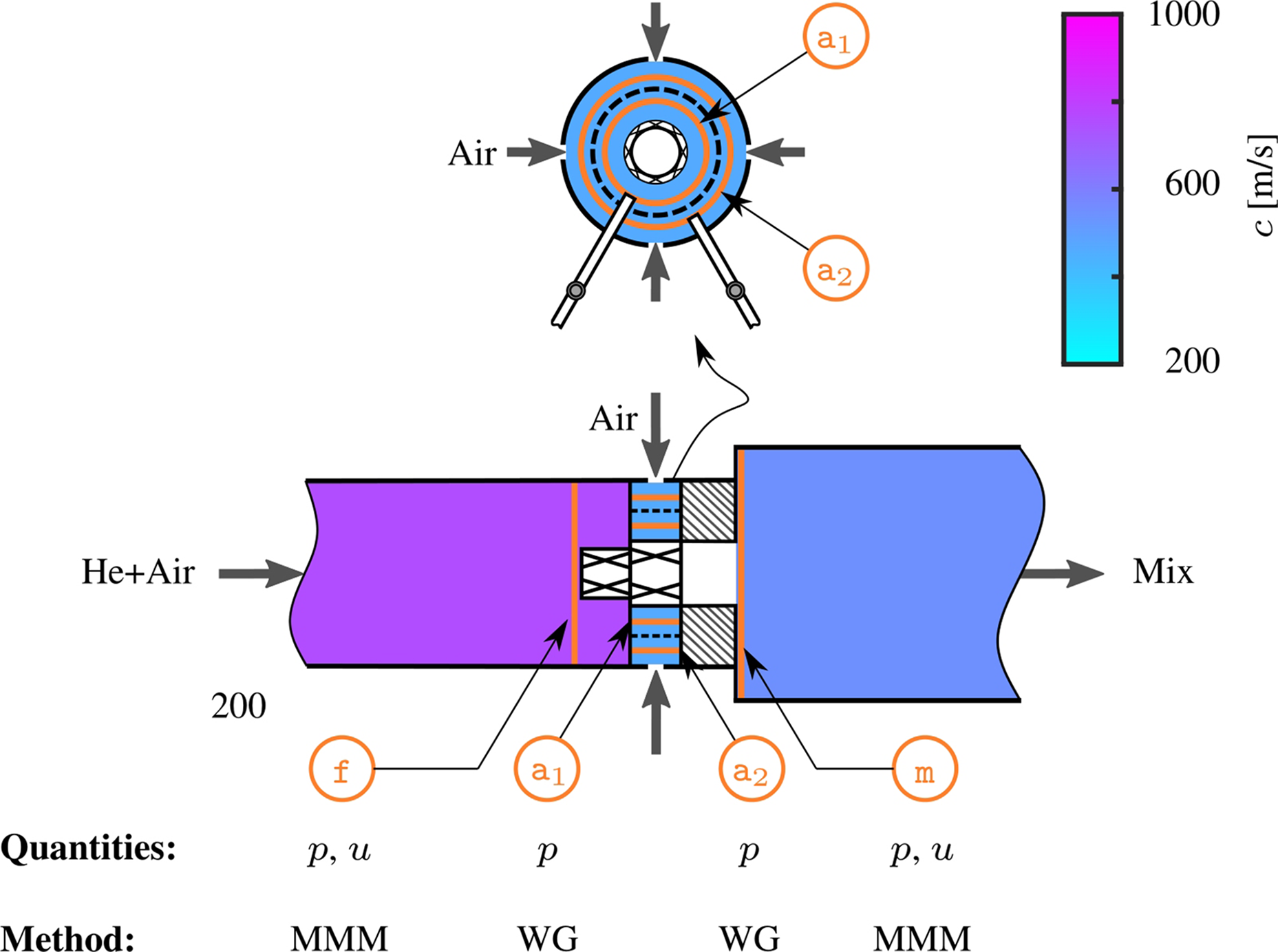
Exemplary speed of sound distribution assumed and quantities measured at reference locations.
Acoustic measurement setup
To characterise the acoustic transmission properties of the dual-swirler, a number of microphones were used. The upstream fuel plenum, which feeds the first swirler stage, accommodated an array of five microphones installed in water-cooled holders at different axial positions. Their signals were analysed using the Multi-Microphone Method (MMM), to identify the upstream and downstream acoustic waves in the duct. These were then combined to obtain acoustic velocity and pressure at reference position ‘
Because of its complex geometry, the radial air plenum could not be equipped with a microphone array. In order to characterise the acoustics in this part of the burner, two Waveguide (WG) systems were installed. They measured the acoustic pressure inside and outside the perforated plate at reference positions ‘
Overall, this setup provided the measurement of acoustic pressure fluctuations at all reference positions and additional measurement of velocity fluctuations at reference positions ‘
Processing of microphone signals
The microphone signals were measured in Volts by analogue input modules from National Instruments. In order to convert them to meaningful acoustic pressure signals, all microphones were calibrated against a common reference microphone by installing them in an impedance tube at the same cross-section and exciting over a range of frequencies. 20 This provided the relative calibration amongst the microphones, which is necessary for the multi-microphone method discussed in the next section. An absolute calibration of the reference microphone using a piston-phone provided the Volts-to-Pascals conversion. 21 To capture only the frequency component coherent to the acoustic forcing, the Cross Power Spectral Density was evaluated for each microphone against the forcing signal. This was then normalised by the Auto Power Spectral Density of the forcing signal to finally obtain the acoustic pressure.
Multi-microphone method
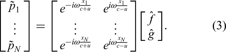
The Multi-Microphone Method (MMM) allows the detection of plane acoustic waves from pressure signals measured by multiple microphones at different axial locations in a straight duct.22,23 For frequencies below the cut-on frequency of the first transverse mode, the response of the acoustic pressure and velocity to harmonic forcing can be expressed as a linear combination of two Riemann invariants (


BTM modelling of a compact two-port burner
The acoustic response of a burner is generally characterised through its SM, by assuming that only planar waves propagate through the burner. This holds true provided that the considered frequencies are low so that the burner can be considered to be acoustically compact. Under this assumption, the SM relates the Riemann invariants travelling into the burner to those travelling out of the burner, as schematised in Figure 4. For a two-port burner, the elements of the SM can be measured experimentally by applying the MMM in the ducts connected to the two ports. Having to identify the four unknown elements of the SM from two equations requires collecting experimental data for two linearly independent acoustic states. This is achieved by forcing the system acoustically from the Upstream (US) and the Downstream (DS) side of the burner, one at a time. The SM represents a causal relation of the acoustic state across the burner, which is often translated into a non-causal relation between the acoustic velocity and pressure states across the burner by using the relations in Equations (1), (2). This results in defining the BTM between the inlet ‘


Top: Acoustic scattering matrix for a classic burner, represented as an acoustic two-port with one inlet (‘
From a modelling perspective, the explicit expressions of the elements of the BTM stem from the conservation of mass and momentum across the burner.
24
For acoustically compact swirl burners, a commonly employed model for the elements of
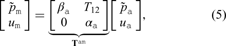



This form has the advantage that it can be generalised to burners with multiple ports, as discussed in the next section. It emphasises that, provided the
BTM modelling of a compact three-port burner
The burner considered in this work has the peculiarity of having two non-stiff inlet ports and one outlet port. To characterise the SM of this burner, one needs to relate the three Riemann invariants travelling into the burner to the three Riemann invariants travelling out of the burner (see Figure 4). The full characterisation of the resulting 3



By combining Equations (9), (10), and (11), the three-port BTM for the dual-swirl burner
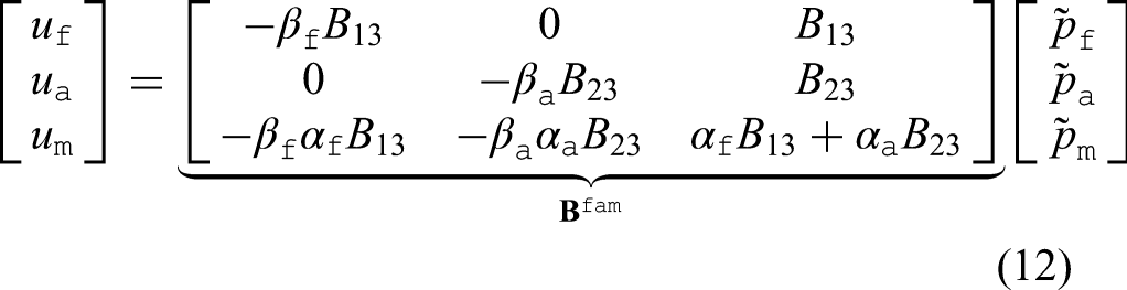
It is important to emphasise that, apart from conserving acoustic mass flux, this ROM assumes no interaction between the two inlet streams. Therefore, the pressure drop across each stream is assumed to be independent of the other stream, leading to
An additional complication was caused by the fact that the experimental setup did not allow for a measurement of the acoustic velocity

This impedance model allows for estimating the acoustic velocity in the air plenum from the two pressure readings at locations ‘
Results and discussion
In order to better understand the acoustic properties of the burner, it was first characterised by blocking one of the two inlet ports. This not only allowed us to study the behaviour of the burner in a conventional manner and compare it with the model for the two-ports but also helped in validating the assumptions made in deriving Equation (12).
Two-port BTM (air plenum blocked)
First, the air swirler was replaced with a dummy part having a solid wall instead of slots, so that the burner becomes a single-swirler connecting the fuel plenum to the exhaust duct. MMM was employed to resolve the acoustic field upstream and downstream of the burner for the two acoustic states resulting from US and DS acoustic forcing. Hence, the full 2
For such a two-port burner, the
Note that for the two-port burner,

Two-port BTM (air plenum blocked) for varying flow momentum and speed of sound. Dashed horizontal lines for the amplitude of
The flow momentum, increasing from dark to light blue hues, has a mild influence on the BTM. The amplitude of
Two-port BTM (fuel plenum blocked)
Similarly, a conventional two-port BTM was measured between the air port ‘
The results for the estimated elements
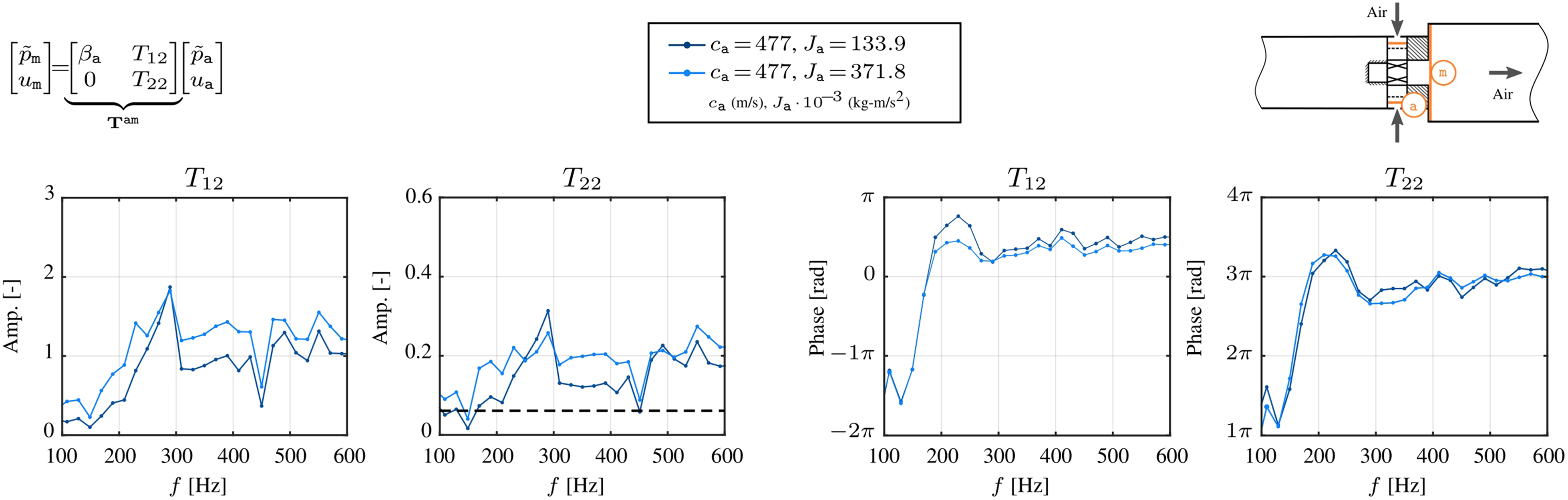
Two-port BTM (fuel plenum blocked) for varying flow momentum. The dashed line for
Three-port BTM (both plena open)
The tests by blocking the air and fuel plena allowed us to demonstrate that the assumptions applicable to a compact burner approximately hold true for the dual-swirl burner. These simplifications offered the possibility to apply a ROM for the 3

Three-port BTM (both plena open) with assumptions. Validation using upstream and downstream acoustic forcing states.
The elements of the third row are, in principle, a linear combination of
In order to better understand the acoustic behaviour of the three-port, the
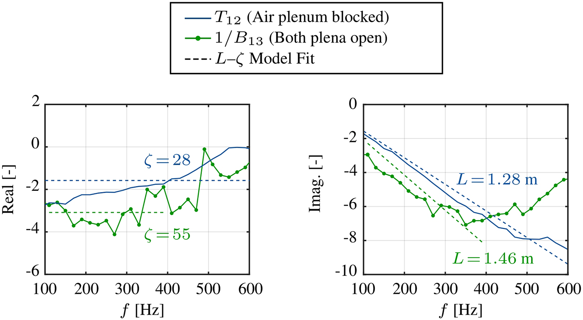
Comparison of
Although both elements represent the impedance for the passage between location ‘
The influence of air-to-fuel momentum and speed of sound ratios on the three-port burner acoustics was assessed by varying the flow through the air plenum, and the flow as well as the speed of sound in the fuel plenum. The results for the amplitude and phase of the TM

Three-port BTM (both plena open) with assumptions. Influence of air-to-fuel momentum and speed of sound ratios.
Conclusions and outlook
This study highlights the importance of treating burners with non-stiff fuel injection as three-port systems to achieve rig-independent BTMs, which are essential for accurate thermoacoustic modelling in practical combustion systems. Unlike the conventional two-port approach, the three-port definition accounts for the influence of multiple inlet flows, enabling a more comprehensive understanding of the acoustic behaviour of complex burners. Although a full three-port definition is necessary for obtaining rig-independent BTMs, it was discussed how the assumption of acoustic compactness, valid at low frequencies, can be used to simplify the experimental characterisation of such systems. These simplifications led to a ROM for the three-port BTM that was obtained by generating only two independent acoustic states with MMM in upstream and downstream ducts, and two extra microphones in the radial air plenum connected to the third port. The presented measurements demonstrate that the
Further improvement of the analysis is possible by experimentally determining the impedance for the perforated plate in the air plenum. This would allow a better estimation of the acoustic velocity from the two acoustic pressures and enable the derivation of a more meaningful BTM. Moreover, generating three independent acoustic states, e.g. by changing the boundary condition in the air plenum in addition to the US and DS forcings, can be exploited to obtain the full three-port BTM without any assumption.
Footnotes

Funding
Declaration of conflicting interests
The authors declare no potential conflicts of interest with respect to research, authorship, and publication of this article.
BTM: Burner Transfer Matrix
DS: Downstream
LSM: Least Squares Method
MMM: Multi-Microphone Method
ROM: Reduced-order Model
SM: Scattering Matrix
TM: Transfer Matrix
US: Upstream
WG: Waveguide