
Abstract
This paper describes a methodology to thermoacoustically account for different flame types in a single Finite-Element-computation. To do so, the flame segmentation mechanism presented in previous studies is used to characterize the different flame zones. Differentiation is done between propagation-stabilized shear-layer flames and autoignition flames that respond to acoustic perturbations very differently. While autoignition flames mainly respond to acoustic pressure and temperature fluctuations, propagation-stabilized flames respond to acoustic velocity perturbations. Thus, flame transfer functions specific to each flame type are analytically implemented within the frequency domain Finite-Element-computation. Using the novel framework, it is shown that the global flame transfer function obtained from Computational Fluid Dynamics (CFD) simulations of a backward facing step reheat combustor can be reproduced accurately in the low-frequency regime for an operating point where the flame is forced in a planar manner. The investigated operating point operates on hydrogen fully premixed at lean and autoignitive conditions. The autoignition framework is validated by comparison to one-dimensional direct numerical simulation. The time-averaged CFD heat release rate result is validated with large eddy simulation data.
Novelty and significance statement
The novelty of this work lies in the incorporation of two different types of flame in a single thermoacoustic finite element method (FEM) calculation. To the best of our knowledge, this has not yet been shown in the literature before. The significance of this work lies within industrial applications. In industrial reheat combustion chambers, the autoignition flame is typically not purely autoignition stabilized, and flame anchoring regions are present which contribute to the stability of the flame.
Introduction
To fulfill the Paris agreement, 1 a large-scale integration of renewable energy systems in the energy landscape is essential.2–4 To stabilize and balance the grid, gas turbines running on carbon-free fuels can be an ideal asset.3,5–9 However, these non-conventional fuels possess very different combustion properties when compared to natural gas. Thus, novel gas turbine combustor development is faced with new challenges to enable the fuel flexible firing capability of an engine. The thermoacoustic analysis to aid the mitigation of combustion instabilities remains a key component in the development phase. 10
There are a variety of methods to perform thermoacoustic analysis of combustion chambers. Direct numerical simulation (DNS)11,12 and large eddy simulation (LES)
13
are considered high-fidelity analysis tools, which are capable of analyzing certain thermoacoustic effects in the highest detail. However, they come with a high computational cost and are unfeasible for entire industrial combustor geometries. Alternatively, Helmholtz solvers in combination with flame transfer/describing functions extracted from computations or experiments have been shown to accurately capture the thermoacoustics of combustion chambers.14–20 Nicoud et al.
14
showed that using a finite element method (FEM) Helmholtz solver the stability of combustion chambers with propagation-stabilized flames could be captured accurately. To do so, the flame transfer function (FTF) was described by an
In this paper, we present an FEM-based approach to thermoacoustically model flames that are partly stabilized by autoignition. The overall flame, which consists of a propagation- and an autoignition part, is analytically described in FEM. The segmentation mechanism from prior studies17,18 is leveraged to define the different flame types. The segmentation mechanism17,27 was initially designed to thermoacoustically model non-compact reheat flames under the influence of transverse combustor eigenmodes. In the case of transverse eigenmodes, the acoustic wavelength is of similar length as the flame, thus, resulting in an acoustically non-compact flame. To deal with this, the segmentation mechanism divides the flame into multiple subflames in transverse direction. Each of the very thin subflames is then considered acoustically compact without variation of the fluctuation quantities across its height. Thus, single values for the pressure, temperature and velocity fluctuations act on each subflame. For each of the subflames, a transfer function can be assigned. In the study presented here, the flame is acoustically compact and as such no segmentation is needed. However, the segmentation mechanism is leveraged to assign a specific FTF to each heat release rate (HRR) region depending on its flame stabilization type. To obtain the flame characterization parameters, Reynolds Averaged Navier–Stokes (RANS) simulations are done using Fluent with an in-house reheat flame model, which is an adaptation and extension of the model derived by Kulkarni et al.28,29 The thermoacoustic analysis is done for a planarly forced backward facing step (BFS) burning hydrogen at elevated pressure.
The presented research is relevant, because in industrial reheat combustors the autoignition flame is never only stabilized by autoignition. Typically, the reheat flame consists of propagation-stabilized HRR regions as well as regions predominantly stabilized by autoignition. Propagation-stabilized flames occur within the shear layers of recirculation zones. Their stabilization is governed by the balance of the flame consumption speed and the flow velocity. With respect to thermoacoustics, the acoustic waves affect the propagation-stabilized flame regions by velocity fluctuations, which modulate the equivalence ratio. In contrast, autoignition stabilized flames are governed by the balance of the autoignition time scale and the flow residence time scale. The fluctuating pressure and especially the isentropic temperature fluctuations induced by acoustic waves affect the local reaction rates and thus the ignition chemistry. This can strongly alter the ignition time and therefore the ignition length, which results in HRR fluctuations. Thereby, the history effect of the fluctuations during the ignition phase matters for reheat flames and is accounted for in current state-of-the-art flame response modeling tools, as presented in Refs. Heinzmann et al., 17 Heinzmann et al., 27 Zellhuber et al., 30 Gant et al., 31 Gopalakrishnan et al., 32 Gopalakrishnan et al. 33
Validation data
The segmentation mechanism developed by Heinzmann et al.17,18 was already validated in prior studies and initially designed to numerically deal with acoustically non-compact flames. This segmentation mechanism can also be efficiently used for the planar wave case to incorporate different flame types. The model is compared to one-dimensional (1D) DNS 32 for a flame solely stabilized by autoignition, and to RANS computations for the partly autoignition- and propagation-stabilized flame in a BFS combustion chamber.
1D DNS simulation
The computational fluid dynamics (CFD) study used for validation in Gopalakrishnan et al.
34
is a compressible 1D DNS computation burning hydrogen fully premixed at lean conditions. The operating pressure is atmospheric with an inlet temperature of 1100 K and an inlet flow speed of 200 m/s. The duct of length 0.3 m with non-reflecting boundary conditions was forced with acoustic and entropic waves at the inlet. For more details on the numerical setup the reader is referred to Gopalakrishnan et al.
34
The duct is modeled in two-dimensional (2D) in FEM with a length of 0.3 m and a height of 0.05 m. The boundary conditions were set to non-reflecting and the

1D DNS configuration schematic of the modeled duct in the FE-solver. The boundaries are forced with
Autoignition flame RANS computation
The 2D RANS CFD computations are performed for a BFS Figure 2 with a total length of 0.3 m. The BFS is located at 0.15 m, with a symmetric area expansion from 0.01 m to 0.02 m. The investigated operating point burns hydrogen and air fully premixed at lean and autoignitive conditions (mass fractions:

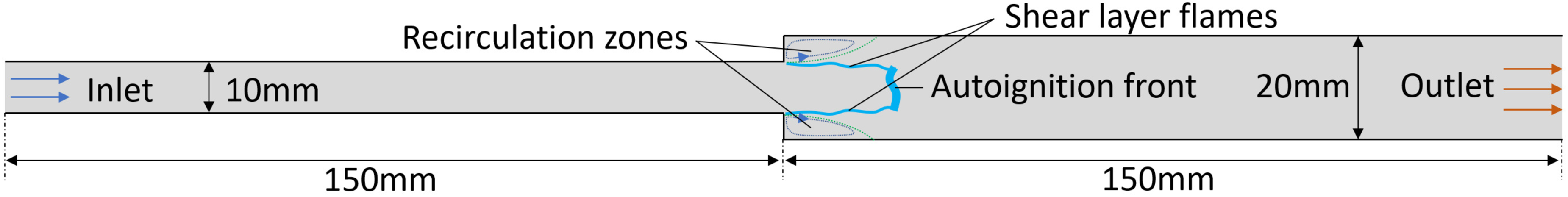
Schematic representation of the backward facing step (BFS) geometry.
Assuming, that the temperature does not change significantly during the radical build up, it can be divided into two parts: The initial temperature

By assuming isentropic correlation of pressure and temperature for acoustic waves,

As

For the turbulence chemistry interaction a presumed beta PDF
37
approach is used. The mean turbulent PV source term is then obtained by folding the source term over a probability distribution

The reaction rate is then computed by multiplying the Eddy Dissipation Model’s 38 reaction rate with the value of the PV in order to delay it until the residence time of a fluid particle is equal to the ignition delay time.
The advantage of this approach is that the correct ignition delay time can be achieved without transporting all the intermediate species and computing their reaction rates. Instead, the PV source terms are computed
For the CFD simulations the realizable
Methodology
Flame response and segmentation
The flame response to planar acoustic waves is characterized differently for the propagation-stabilized shear layer flames and the autoignition flame. For the shear layer flame, an

For the autoignition flame, the framework from Gopalakrishnan et al.
32
is used to quantify the flame response. The total autoignition HRR response of the flame is assumed to be a linear superposition of the individual flame responses (FTFs) to the acoustic and entropic waves.
31
Equation 8 represents the HRR FTFs


The local acoustic field is evaluated from the FEM solution. For the propagation-stabilized flame regions, the local velocity fluctuation is used together with the prescribed


FEM implementation
To characterize the flame in the FEM simulation and solve the inhomogeneous Helmholtz equation (Helmholtz equation with source terms), the numerical segmentation mechanism derived by Heinzmann et al.17,18 is used. A main benefit of the segmentation is, that simulations can be done for non-compact flames, that is, flames that are under the influence of transverse eigenmodes. Figure 3 schematically visualizes the segmentation mechanism. Differentiation is made between propagation-stabilized subflames (blue circles) and the autoignition subflames (magenta circles). Due to the fine segmentation, it can be assumed that for each subflame a single value for the pressure and velocity perturbation is present. Thus, the flame also reacts with a single value for the HRR and the flame movement. For each of the subflames, specific FTFs can be implemented to capture the different flame responses of propagation-stabilized and autoignition flames. Hence, the segmentation mechanism allows different flame types in the same FEM computation.
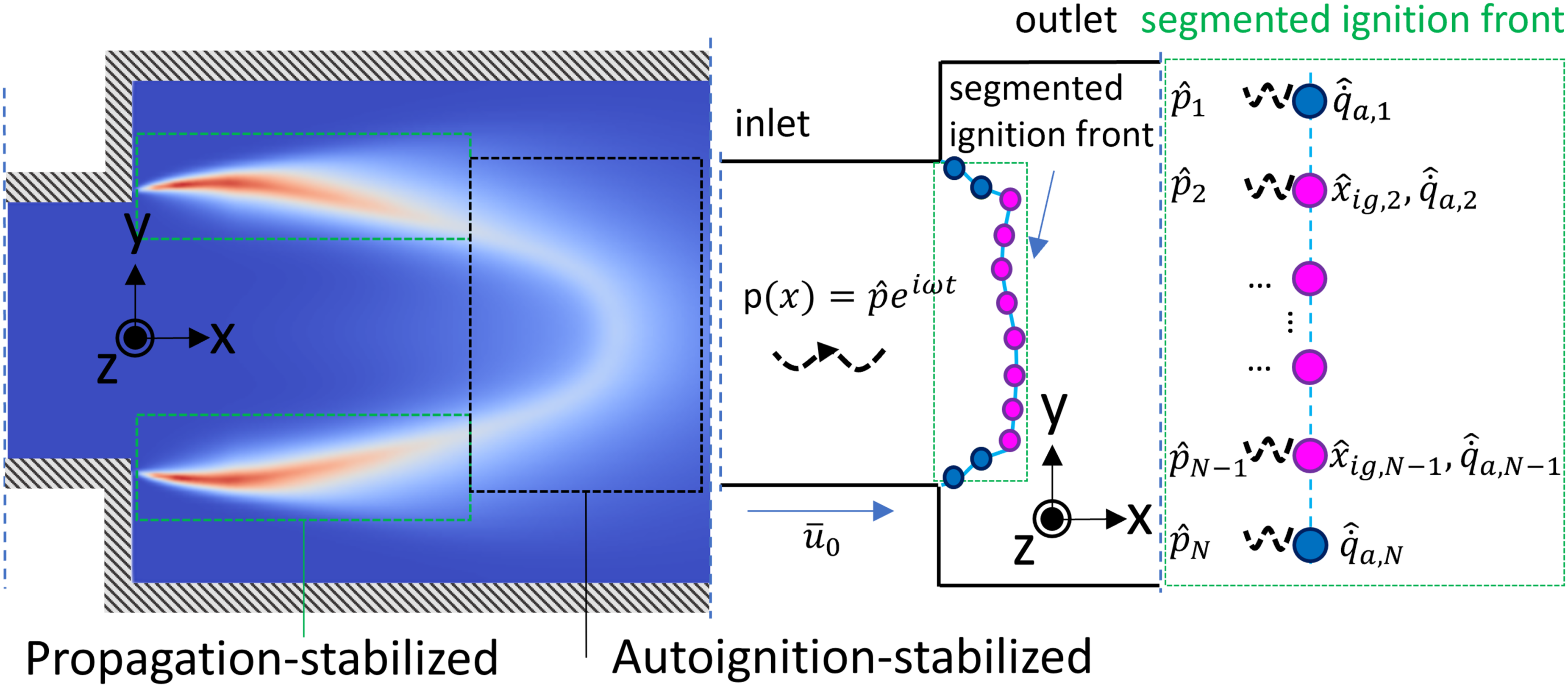
Numerical segmentation method for a perturbed partly autoignition and propagation-stabilized flame in two-dimensional (2D). The blue circles indicate the propagation-stabilized flame parts, and the magenta circles represent the autoignition flame.
For the propagation-stabilized flame parts (Equation 12) as well as the autoignition flame regions (Equation 13), Gaussian kernels are used to analytically position the flame in the computational domain.


The parameters for the HRR width, the mean flame position and the integrated HRR can be calculated from either CFD mean field solutions or experimental chemiluminescence imaging if available. Using these quantities and the assumption of the Gaussian kernel in x-direction (multiple studies used Gaussian distributions17,30,31,34,43), the average flame can be rebuilt fully in FEM. Whilst the procedure here is done in 2D on the
At this point, the average flame is fully characterized in the FEM simulation and what remains to be characterized is the representation of the fluctuating HRR perturbations. This is achieved by obtaining the instantaneous HRR after multiplying the mean HRR by the FTF Equation 8 (for the propagation-stabilized flame Equation 6, respectively) and accounting for the flame motion in the Gaussian distribution (shift of the center of the Gaussian kernel) using Equation 9 to obtain Equations 14. For the propagation-stabilized flame region, no flame motion is introduced due to the anchored nature of the flame.

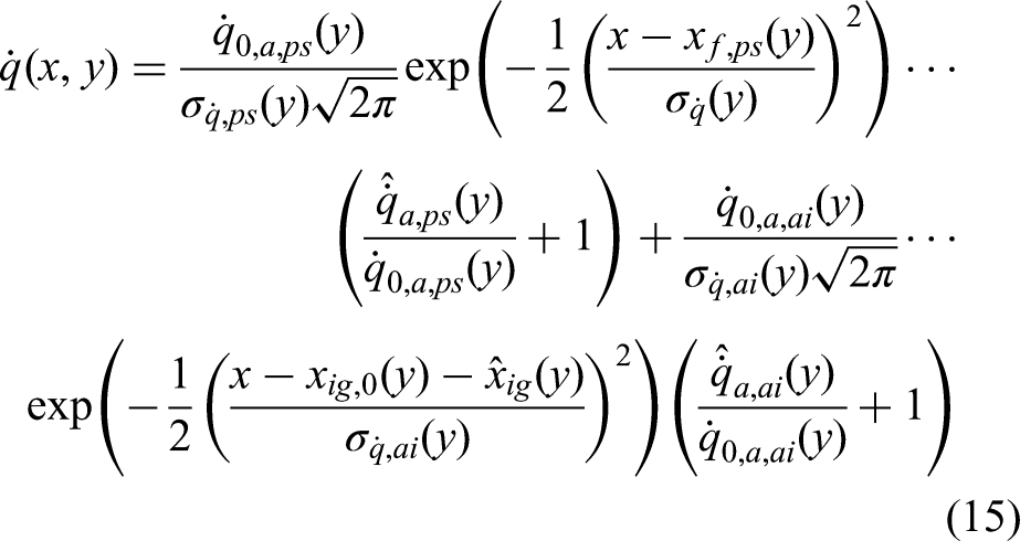
Using Gaussian kernel distributions for both flames the instantaneous volumetric HRR is obtained (Equation 15).
The fluctuating HRR

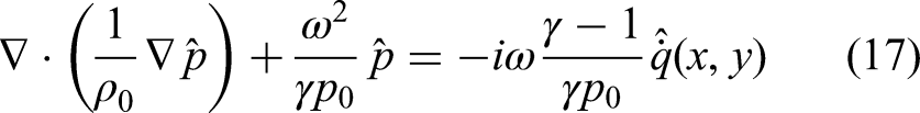
The equation for the inhomogeneous Helmholtz equation, which is solved in FEM (in the frequency domain), thus becomes Equation 17 by adding the source term to the right-hand side of the homogeneous Helmholtz equation. From the computations the eigenfrequencies and linear growth rates are extracted. In this study COMSOL 6.2 is used.
Results
Results obtained by implementing the proposed methodology are shown in the following section.
1D DNS forced
Figure 4 shows the intermediate result obtained in comparison with the DNS simulation to validate the FEM implementation of a flame solely stabilized by autoignition. An excellent match is achieved in comparison with the DNS result in both phase and magnitude. The small deviation in phase could result from neglecting mean flow effects by employing the Helmholtz equation.

Comparison of the HRR fluctuations for the 1D DNS configuration forced at 100 Hz. The solid line represents the DNS data and the dashed line the FEM result. FEM: finite element method; 1D: one-dimensional; DNS: direct numerical simulation.
Mean fields of the BFS burning hydrogen
Figure 5 shows the time-averaged mean fields from the RANS simulation. Figure 5(a) shows the

Mean field solutions of the Reynolds averaged Navier–Stokes (RANS) simulation: (a)
The time-averaged flame shape is computed using the in-house autoignition reheat flame model described in the CFD section. To validate the mean field qualitatively, comparisons to center-plane data from the described LES simulation are made. The comparison between the results from the LES and the RANS simulations shows that the model can replicate the flame to a certain extent. The mean ignition-length and overall flame shape is captured well (length scales are small). The RANS simulation however predicts the propagation-stabilized shear layer flames to be further upstream compared to the validation data. Experience shows, that the occurrence of an earlier timed ignition is linked to the RANS solver used in combination with the reheat flame model.
Further comparisons can be made by analyzing the volumetric HRR of Figure 6 for two different sections in Figure 7. The three dash-dotted blue lines show the normalized volumetric HRR along a section (
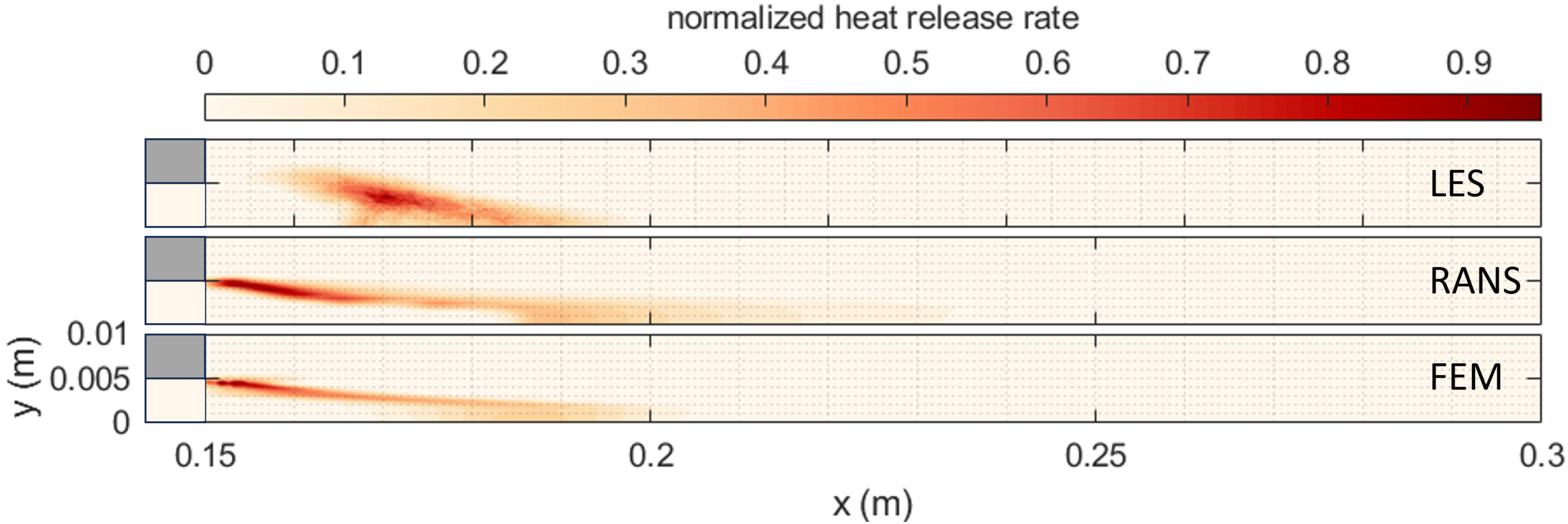
Comparison of the mean HRR between LES (top) RANS (middle) and FEM (bottom). The backward facing step is located at
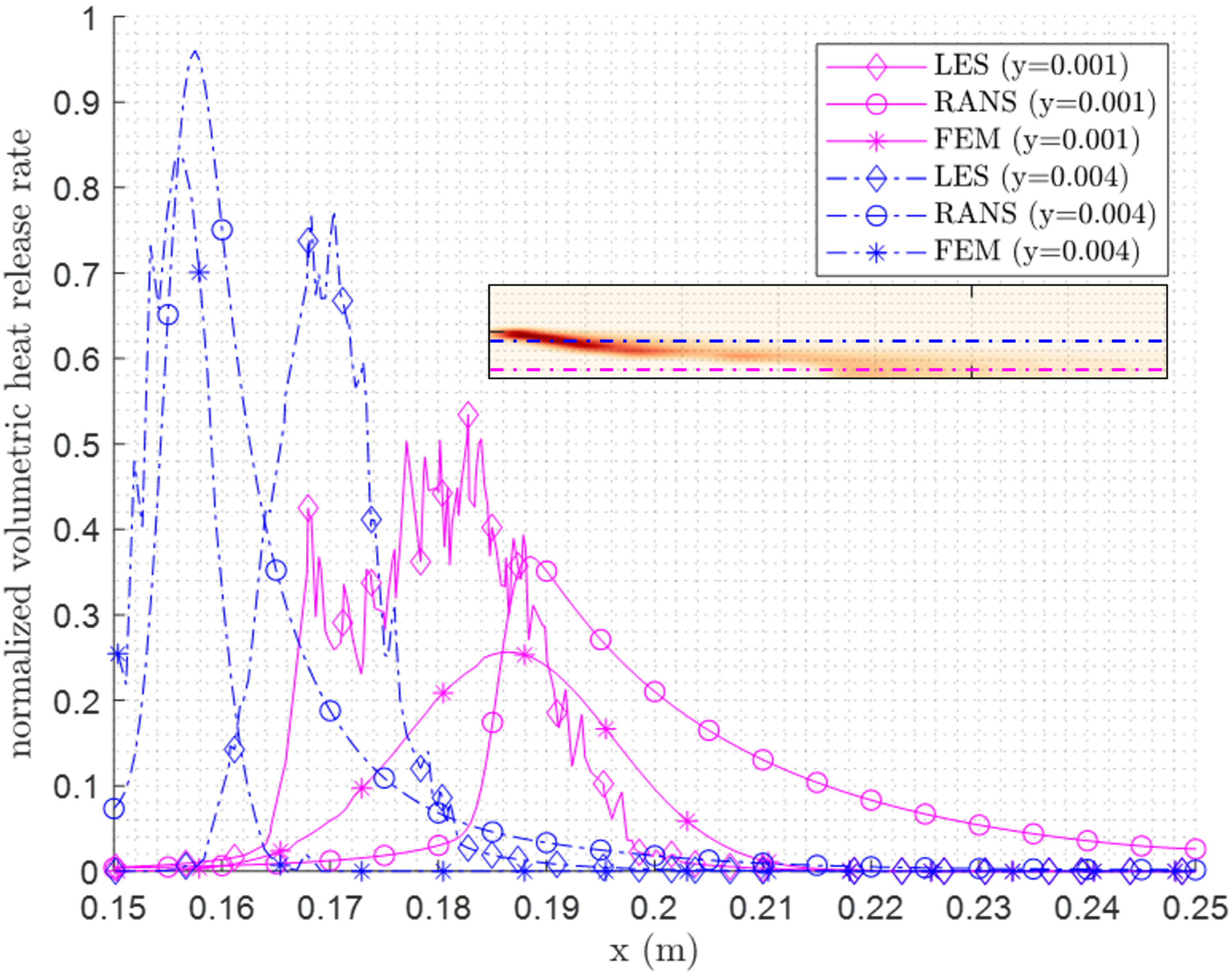
Comparison of the volumetric HRR of different sections through the shear layer flame (blue dash-dotted lines.) and the autoignition stabilized part (solid lines). The comparison is made between the LES (diamonds), RANS (circles) and the FEM (stars). RANS: Reynolds averaged Navier–Stokes; FEM: finite element method; LES: large eddy simulation.
The forced FEM simulation is set up identically to the RANS computation by forcing harmonically at the inlet with a pressure amplitude of 0.5%. The outlet is set to fully anechoic to mitigate reflections and upstream traveling acoustic
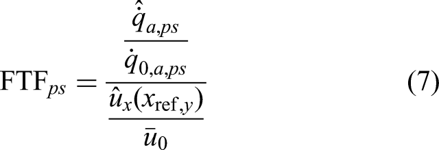
Figure 8 shows the FTFs

FTF Comparisons between the CFD results (diamonds) and the FEM computation (circles). The blue dashed line represents the used
For completeness, Figure 9 shows the used FTFs (with respect to the velocity fluctuations

FTF Comparisons between the
Conclusion
With reheat combustors becoming of increasing interest in industrial gas turbines, autoignition flames have shifted into the scope of current research. Especially in industrial reheat combustion chambers, an autoignition flame will likely have certain flame regions that are propagation-stabilized due to either flow recirculation or vortex breakdown. So far, research on thermoacoustics, especially the flame dynamics, has been performed separately for propagation-stabilized flames and autoignition-stabilized flames. In this paper, we propose an analytical model to predict the response of a composite flame partly stabilized by propagation and partly by autoignition. We leverage a previously developed segmentation method to incorporate both flame types in the same FEM computation. Using the segmentation mechanism, different FTFs are prescribed to the propagation- and autoignition-stabilized flame regions. For the propagation-stabilized HRR regions, a classical
Footnotes
Funding
The authors disclosed receipt of the following financial support for the research, authorship, and/or publication of this article: The research work presented in this manuscript was carried out within the FLEX4H2 project. The FLEX4H2 project is supported by the Clean Hydrogen Partnership and its members European Union, Hydrogen Europe and Hydrogen Europe Research (GA 101101427), and the Swiss Federal Department of Economic Affairs, Education and Research, State Secretariat for Education, Research and Innovation (SERI). Views and opinions expressed are however those of the author(s) only and do not necessarily reflect those of the European Union or any other granting authority. Neither of them is liable for any use that may be made of the information contained therein.
Declaration of Conflicting Interests
The authors declare no potential conflicts of interest with respect to research, authorship, and publication of this article.