
Abstract
With the increasing application of construction robots on construction sites, autonomous path planning in unstructured and uneven construction sites has become an urgent challenge. Current path planning approaches face several issues, including prolonged computation times, low efficiency, and redundant nodes, often resulting in impractical paths for robots. Addressing these concerns, this study introduces a global path planning method based on an enhanced A* algorithm to ensure safe and robust navigation of construction robots in such challenging environments. The Improved A* algorithm initially incorporates a bidirectional alternating search strategy to expedite computational speed. Subsequently, it employs path node filtering to mitigate issues associated with bidirectional search and reduce the number of critical nodes, thereby enhancing search efficiency. Furthermore, the introduction of slope constraints decreases the robot's climbing and tilting angles, augmenting the safety of the planned paths. Finally, the paths are smoothed using Bézier curve fitting, facilitating better motion control for the robots. The efficacy of the improved algorithm was validated through experiments on elevation maps with varying terrain and obstacle densities. Simulation results indicate that, compared to the traditional A* algorithm, the Improved A* algorithm reduced computation time by 71.05% to 82.90% and the number of critical nodes by 51.94% to 70.53%, while only increasing the path length by 14.6% to 37.84%. Additionally, there was a significant reduction in climbing and tilting angles, and the paths have become smoother. Therefore, this method not only improves efficiency while generating safe and reliable paths in unstructured and uneven construction sites, but also enables robots to adapt to complex environments, and promotes automation and intelligent construction processes.
Introduction
In recent years, the rapid development of automation technology has led to the increasingly widespread deployment of robots in the construction industry, marking a global trend in their integration into construction processes (Jeong et al., 2021). In response to this evolution, researchers have proposed robotic systems equipped with perception sensors and intelligent algorithms designed to assist construction supervisors in remotely identifying building materials and detecting component installations and defects (Muhammad et al., 2021). The application of Virtual Reality (VR) technology in conjunction with construction robots has significantly enhanced workers’ trust in robots, self-efficacy, and situational awareness at construction sites (Adami et al., 2022). Furthermore, to address the challenge of initializing robots at unknown locations, a novel indoor robot initialization system based on Building Information Modeling (BIM) has been introduced, utilizing object detectors for automatic initialization (Zhao and Cheah, 2023). Despite significant progress in developing construction robot solutions, the unique characteristics of construction sites, such as temporary structures, equipment, and materials, pose considerable challenges for mobile robots. The complex and uneven terrain further complicates the path planning methods required for these robots.
Global path planning is one of the basic issues in robotics technology and the basis for robots to complete complex tasks (Li et al., 2022a). It is a kind of static planning, usually expressed as follows: given a mobile robot and an environment model, it must find the optimal path between the starting position and the final position without colliding with obstacles, while meeting certain criteria, such as distance, smoothness or safety (Châari et al., 2014; Saeed et al., 2020). The results of path planning can be evaluated in terms of path length, turning angle, calculation time, risk level, and other factors (Zhang et al., 2022). With the advancement of Simultaneous Localization and Mapping (SLAM) technology and improvements in computational performance, autonomous navigation techniques have found widespread application in ground robots. Currently, two-dimensional indoor planar mobile robot navigation technology is relatively mature. By enhancing the robustness and efficiency of existing two-dimensional autonomous navigation methods (Kalogeiton et al., 2019; Pütz et al., 2018), robots are now extensively deployed in various fields such as industry (Cardarelli et al., 2017), agriculture (Tevyashov et al., 2022), search and rescue (Berger and Lo, 2015), and transportation (Pereira et al., 2018). However, traditional path planning algorithms are primarily designed for flat, structured terrains and tend to idealize environmental conditions. Given that construction sites in the early stages are often scattered with rocks, soil piles, and slopes, mobile robots must determine whether the terrain ahead is safely traversable. In other words, devising the most practical and collision-free paths on uneven and unstructured terrains is a critical challenge. In such complex environments, traditional path planning algorithms face several difficulties and limitations, including:
The representation and computation of large-scale maps are time-consuming. Unstructured terrains and obstacles severely affect the planning of paths. The paths generated by planning do not meet the safety requirements of mobile robots.
Construction robots are a specialized application of mobile robots in specific scenarios. Given that mobile robot path planning is widely regarded as an NP-hard problem (Kyprianou et al., 2021), extending path planning to three-dimensional (3D) environments merely involves adding a height axis compared to two-dimensional (2D) plane-based path planning. Consequently, 3D path planning also falls within the NP-hard problem category (Zeng et al., 2016). In previous decades, several approaches have been developed to address this complex issue. Classic methods include artificial potential fields, sampling-based methods, and graph-based methods; heuristic algorithms mainly include A* and D* search algorithms; meta-heuristic algorithms have been applied in most research, such as the famous algorithms are Particle Swarm Optimization (PSO), Genetic Algorithm (GA), and Simulated Annealing (SA); methods based on artificial intelligence are among the most prevalent algorithms utilized in multi-robot systems, for example, Yakoubi MA and colleagues employed a Pulse-Coupled Neural Network model to achieve complete coverage navigation for a vacuum cleaner robot (Yakoubi et al., 2016). These algorithms have solved the path planning problem of mobile robots in a known environment to a certain extent. The classification of methods is shown in Figure 1.
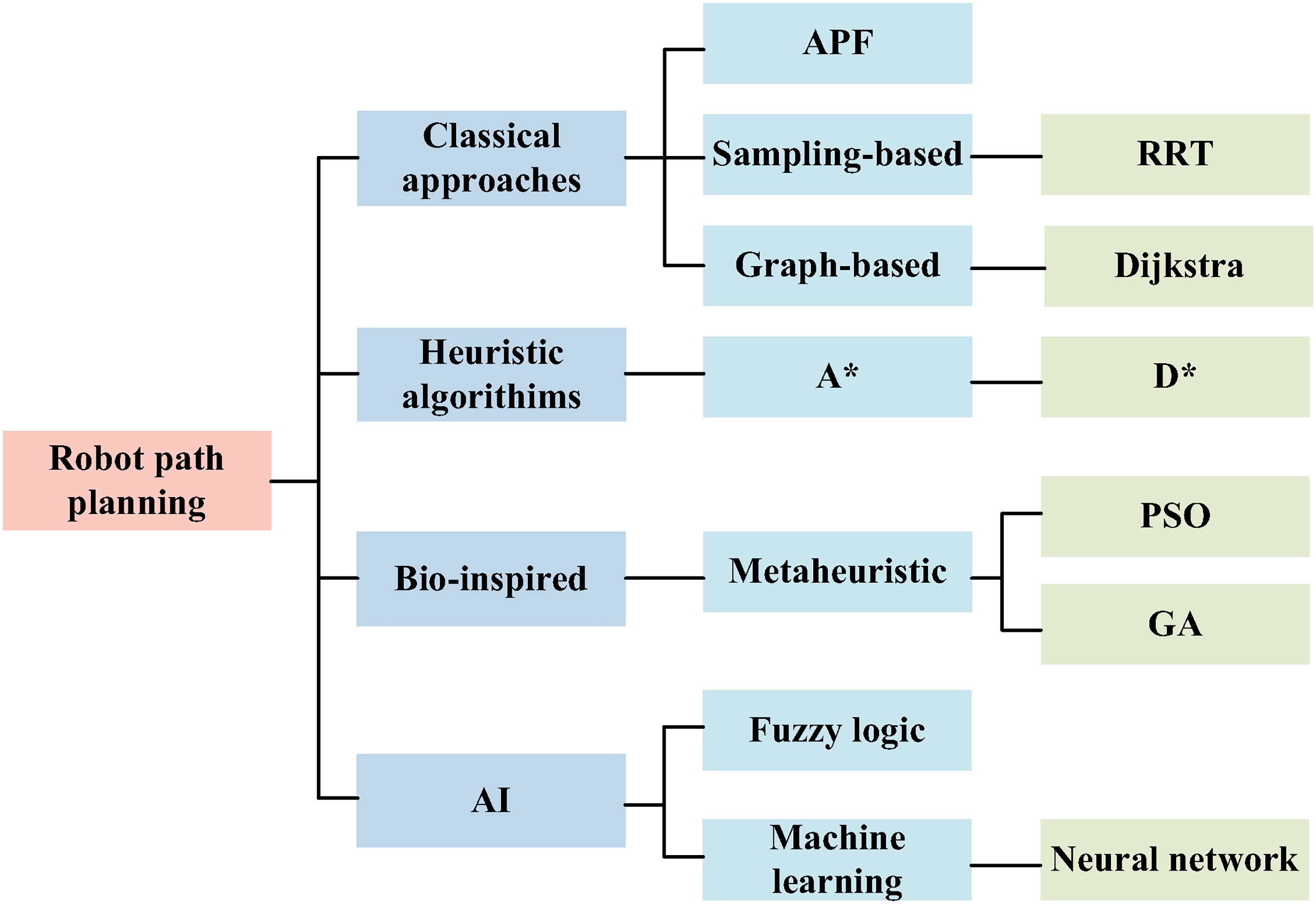
Classification of commonly used path planning methods.
In the realm of meta-heuristic algorithms, the Genetic Algorithm (GA) is widely applied in path planning due to its parallelism and global search capabilities. However, GA has the potential for premature convergence and is prone to falling into local optima (Elhoseny et al., 2018). The Simulated Annealing (SA) algorithm is used in global path planning to search for the optimal path. It is easier to implement than GA, as GA uses a population containing a set of chromosomes rather than a single solution (Miao and Tian, 2013). Despite this, SA has issues with slow convergence speed and large computational overhead (Liang and Xu, 2009). The Ant Colony Optimization (ACO) algorithm proposed by Dorigo is a heuristic search algorithm that simulates the foraging behavior of ant colonies (Dorigo and Gambardella, 1997). It has the advantages of strong robustness, excellent distributed computing performance, and ease of combination with other algorithms (Luo et al., 2019). Nonetheless, ACO has a slower convergence speed and is prone to falling into local optima (Miao et al., 2021). The Particle Swarm Optimization (PSO) algorithm is a swarm intelligence algorithm that simulates bird flocking behavior (Kennedy and Eberhart, 1995). It generates swarm intelligence to guide optimization search through cooperation and competition among particles in the swarm. Although PSO has the advantages of fewer individuals, simple computation, and good robustness, its convergence accuracy is lower, and it experiences search stagnation (Yuan et al., 2022).
Meta-heuristic algorithms are often used for path planning problems in static environments. However, when the environment changes, the time to replan is lengthy, and real-time performance is lacking. These algorithms also have a tendency to fall into local optima, hence their application in actual robots is limited. Among classical algorithms, the Rapidly-exploring Random Tree (RRT) is a sample-based search algorithm (LaValle and Kuffner, 2001). It is fast and powerful, holding a significant position in high-dimensional environments. Yet, this algorithm has low search accuracy, poor path smoothness, and struggles to plan the optimal path (Kuffner and LaValle, 2000). Dijkstra algorithm is a typical single-source shortest path search algorithm. Its search method is relatively simple, extending from the starting point to the outer layer until it reaches the target point. This is achieved by comparing all nodes through forward traversal to obtain the shortest path (Dijkstra, 1959). Dijkstra's algorithm has a high success rate in obtaining the shortest path and good robustness. But when the scale of environment mapping increases, the number of nodes calculated by the algorithm increases, and the memory space occupied by the algorithm also increases, severely reducing computational efficiency (Chen et al., 2013).In 1968, Hart proposed the A* algorithm, which added a heuristic function based on Dijkstra's algorithm. By evaluating the cost of nodes, it obtains the suboptimal nodes that need to be expanded until the algorithm expands to the target point (Hart et al., 1968). Compared with Dijkstra's algorithm, the path planning efficiency of this algorithm is significantly improved. The A* algorithm is favored by many scholars in the field of mobile robot path planning due to its simple principle, ease of implementation, and high search efficiency (Hong et al., 2021; Li et al., 2022b). Nevertheless, the A* algorithm has defects such as long computation time for large maps, large turning angles, redundant nodes, and unsmooth paths.
In order to enhance the efficiency of the A* algorithm, scholars have made improvements in multiple aspects such as data structure, retrieval strategy, path length, turning angle, and redundant nodes, thereby further enhancing the planning efficiency and path performance of the A* algorithm in various application scenarios. Cui et al. improved the search distance of the A* algorithm by expanding adjacent states, which shortened the planned path and improved search efficiency (Baoxia et al., 2018). Zhang, Ren, and others adopted a key point selection strategy for secondary planning to reduce the search for unnecessary nodes and improve path planning efficiency (YiYue et al., 2019; Zhang et al., 2018). Li et al. combined the Dynamic Window Approach (DWA) with the A* algorithm, giving the algorithm a certain dynamic obstacle avoidance capability and improving the robustness of the algorithm (Li et al., 2022b). Shang et al. improved the efficiency and obstacle avoidance capabilities of the A* algorithm by using criteria and key points (Shang et al., 2020). Wang et al. have effectively addressed the issues of shortest path planning and collision by incorporating a turning factor into the algorithm (Shang et al., 2020). Hong et al. improved the data structure of the algorithm, reducing its time complexity, and applied the A* algorithm to outdoor path planning (Hong et al., 2021), Gomathi N and others developed a hybrid algorithm, HSAStar (Hybrid SLAM & A Star), which offers a unique adaptive path planning framework to address the unknown environment persistent monitoring problem (Gomathi and Rajathi, 2023).
However, when conducting path planning in the uneven terrain environment of a construction site, it is necessary to consider factors such as obstacles and terrain slopes. Compared to a two-dimensional plane, the constraints imposed by the environment are greater, and the requirements for the algorithm are higher. The aforementioned improvements cannot solve the issues of the traditional A* algorithm, such as long computation time, numerous redundant nodes, unsmooth paths, and safety concerns. To summarize, there is currently little research on quickly planning a short, feasible, smooth, and safe path on a large, uneven surface. Therefore, this paper proposes an improved A* algorithm that significantly enhances algorithm efficiency and can plan a trajectory suitable for construction robots to move on uneven terrain with high smoothness.
The contributions of the method proposed in this paper are summarized as follows:
Construction of a Three-Dimensional Grid Map: By incorporating elevation data into the traditional two-dimensional grid map, a three-dimensional elevation grid map has been established to describe the uneven terrain of unstructured construction sites. Algorithm Improvement: Comprehensive improvements have been made to the traditional A* algorithm from aspects such as bidirectional search strategy, node quantity, and path smoothness. This has greatly enhanced the computational speed of the algorithm and the quality of the path. Establishment of Safety Constraints: Constraints on the climbing angle and tilt angle when the mobile robot moves on an uneven surface have been established, ensuring that the planned path is suitable for the robot's movement in uneven construction site.
The remainder of this paper is organized as follows: Chapter 2 presents the environmental model and the traditional A* algorithm. Chapter 3 details the multiple improvements made to the traditional A* algorithm. In Chapter 4, the effectiveness and significance of the proposed method are validated through experiments, and the research results are presented. Finally, Chapter 5 provides a summary of the entire paper and draws conclusions.
Elevation grid map
To achieve path planning for mobile robots, it is essential to acquire environmental map information. Environmental maps can be broadly categorized into static maps based on terrain and fixed obstacles, and dynamic maps that account for moving obstacles. The acquisition methods primarily involve importing known map information (static maps) or utilizing onboard sensors to detect the dynamic environmental map. Common environmental modeling methods currently include the Visibility Graph Method, Tangent Graph Method, Voronoi Diagram Method, Free Space Method, and Grid-based Method. In the current state of research and practical applications, the grid-based method stands out as the most extensively studied and widely utilized approach for modeling environments in the context of path planning. This method partitions the free space into non-overlapping grid cells, with each cell individually recording terrain information. Specifically, each grid cell represents a discrete portion of the environment. These cells are categorized as either “free” or “occupied.” A free grid cell indicates that a mobile robot can move to that location, while an occupied grid cell signifies the presence of an obstacle, rendering it inaccessible for robot traversal. The environment maps constructed using the grid-based method are commonly referred to as “grid maps.”
Conventional raster maps can only create two-dimensional environmental maps, as illustrated in Figure 2. In contrast, Digital Elevation Models (DEMs) represent the spatial distribution of terrain using a finite three-dimensional vector set
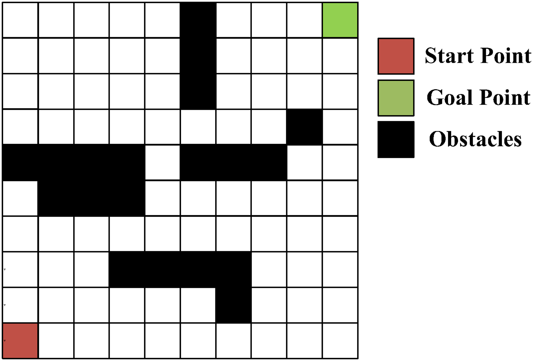
Two-Dimensional grid map.
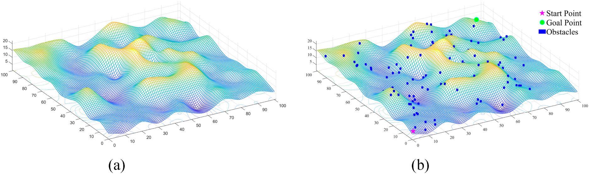
The establishment process of an elevation raster grid map depicting uneven terrain. (a) Elevation grid map. (b) Elevation grid map with obstacles.
The fundamental element of grid-based methods is grid granularity. If the grid cells are too small, the path search process becomes challenging, consuming significant computational resources and time. Conversely, if the grid cells are too large, the environmental model will deviate significantly from the real environment, rendering expected path planning infeasible. Therefore, grid granularity is crucial for both environment modeling and path planning. In this study, we use a resolution of 100 × 100 for the grid map, with each grid cell having an actual side length of 0.5 meters. The actual grid distance can be adjusted based on the size of the mobile robot and the real-world map.
The A* algorithm is a widely used heuristic search algorithm for static environments. It can be applied to path planning in known and fixed environments, and it can also adapt to dynamic environments by repeatedly invoking the algorithm for path planning. The primary characteristic of the A* algorithm is its use of a heuristic function to guide the search direction. The graph being searched has weights that remain constant over time, allowing direct search within the graph without the need for any preprocessing. The core of the A* algorithm lies in its evaluation function, which directs node expansion during each search iteration, as shown in Equation (1).

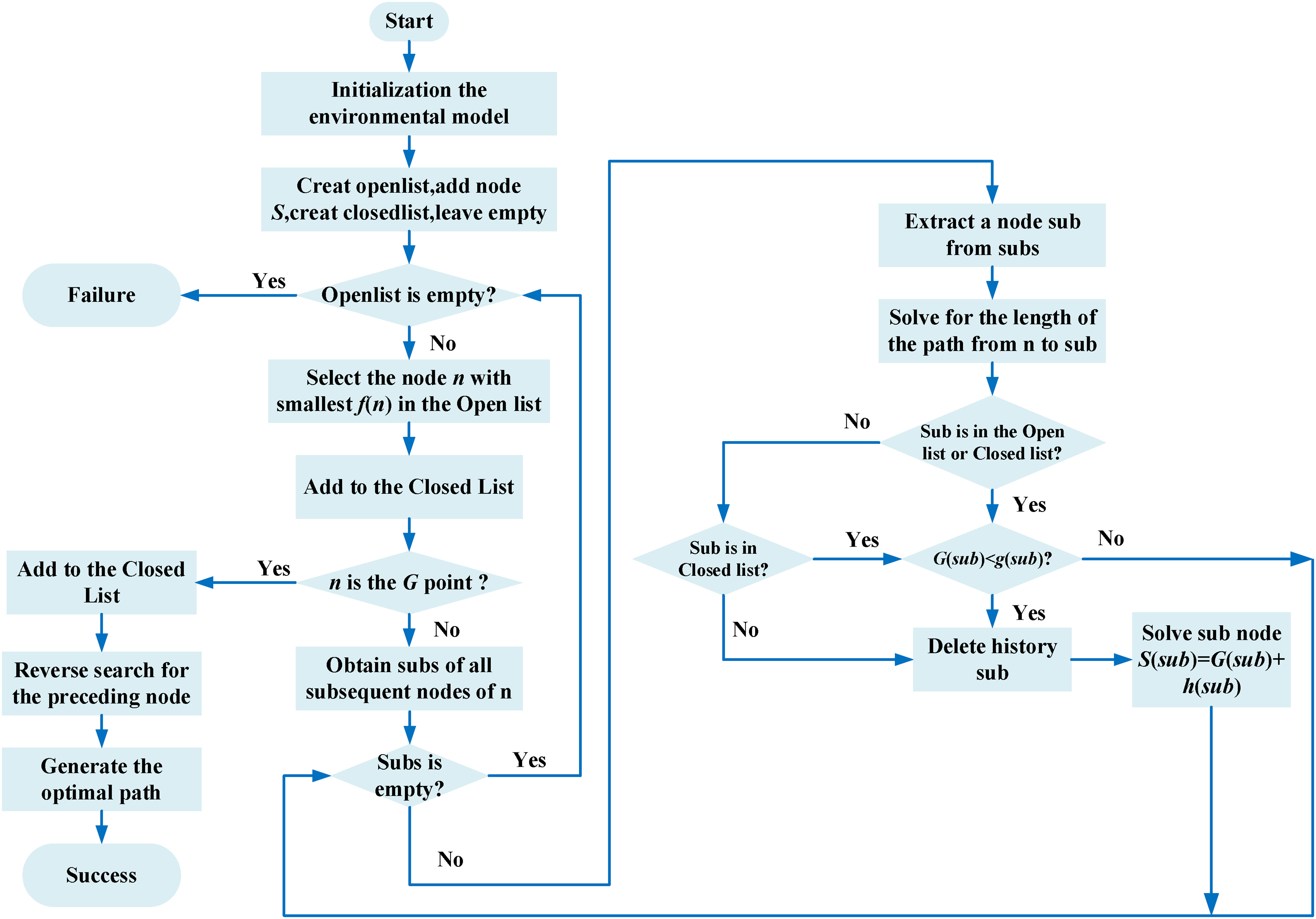
The flow chart of the A* algorithm.
The main steps of the A* algorithm are as follows:
Initialize an OpenList, CloseList, and PathList. Insert the Start node into the OpenList. When the OpenList is not empty, determine the node with the smallest Traverse the feasible neighboring nodes of the current node. If a neighboring node is not in the OpenList, add it to the OpenList, add the current node to the PathList, and calculate the heuristic distance cost. If it is in the OpenList, calculate its G value; continue to traverse other feasible neighboring nodes; otherwise, add the current node to the PathList and update the heuristic distance cost of the node. Iterate to move to subsequent nodes until the current node becomes the end node.
Commonly used heuristic functions
The Euclidean heuristic function between


It is straightforward to prove that the improved heuristic function remains monotonic and admissible, just as the original heuristic function was. Consequently, the improved heuristic function, like the original one, preserves both completeness and optimality. It should be noted that, due to the increased complexity of the improved heuristic function, the enhancement of the heuristic alone does not lead to an increase in the algorithm's computational speed. Instead, it improves the accuracy of the estimated path length by bringing it closer to the actual path length. Regarding the selection of the evaluation function

Schematic diagram of the four and eight moving directions of the robot in the grid map. (a) Four moving directions. (b) Eight moving directions.
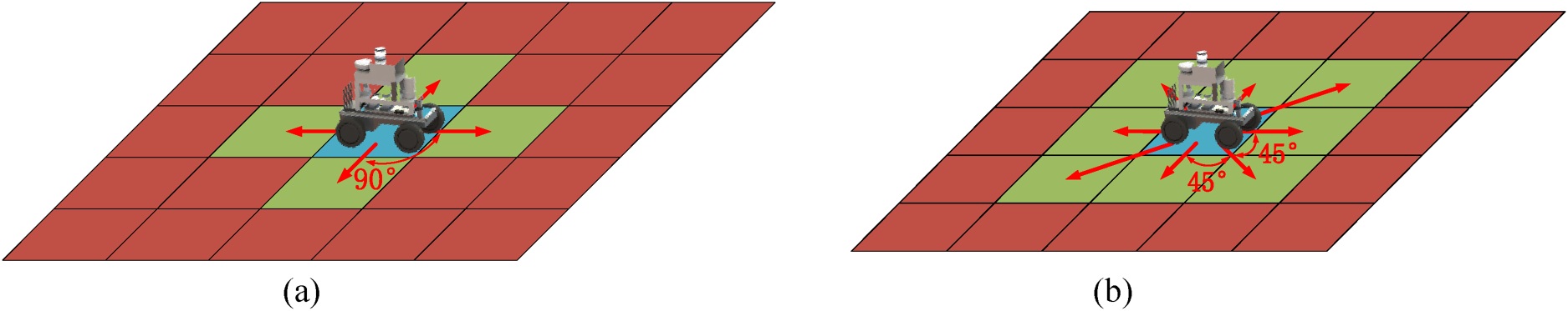
Ground robots cannot move arbitrarily in the actual moving process, and need to be constrained in multiple aspects. The constraints are as follows:
Path Continuity: The planned global path must be continuous. During the movement process, when moving to the next grid, it can move to a feasible grid among the 8 grids around it, as shown in Figure 5. For example, when the current node Boundaries and Obstacles: The planned global path must be within the designated grid map and cannot exceed the map boundary. Grids with blue cylinders are the locations of obstacles, and thus, these grids are not feasible, while other grids are feasible. Shortest Path: After satisfying conditions (1) and (2), the length of the planned global path must be the shortest, that is, the fitness function must take the minimum value. The traditional A* algorithm commonly uses distance calculation methods such as Manhattan distance and Euclidean distance. To make the algorithm adapt to uneven terrain, this paper proposes a new distance calculation method - slope distance (Sd). This distance is closer to the real value in the actual map than the Euclidean distance. The fitness function is expressed as:

In the equation, n is the total number of nodes in the planned path,
To facilitate research and experiment, this paper makes the following assumptions:
The elevation map data has been obtained through other techniques, and this paper focuses solely on constructing the raster elevation map. The grid is expanded using an eight-neighborhood approach, allowing the robot to move to the surrounding eight grid cells when conditions permit. Dynamic map information is captured and updated in real-time by onboard sensors on the robot. These sensors can detect the terrain status of the surrounding eight grid cells at the current grid point.
In addition to the improvements to the heuristic function mentioned earlier, this study further enhances the A* algorithm by incorporating advancements in four key areas: bidirectional alternating search strategy, path node filtering, slope constraint, and arc optimization. These enhancements collectively improve the algorithm's performance in terms of the computational speed, number of critical nodes, climbing angle, and path quality. The flowchart of the improved A* algorithm is shown in Figure 6.
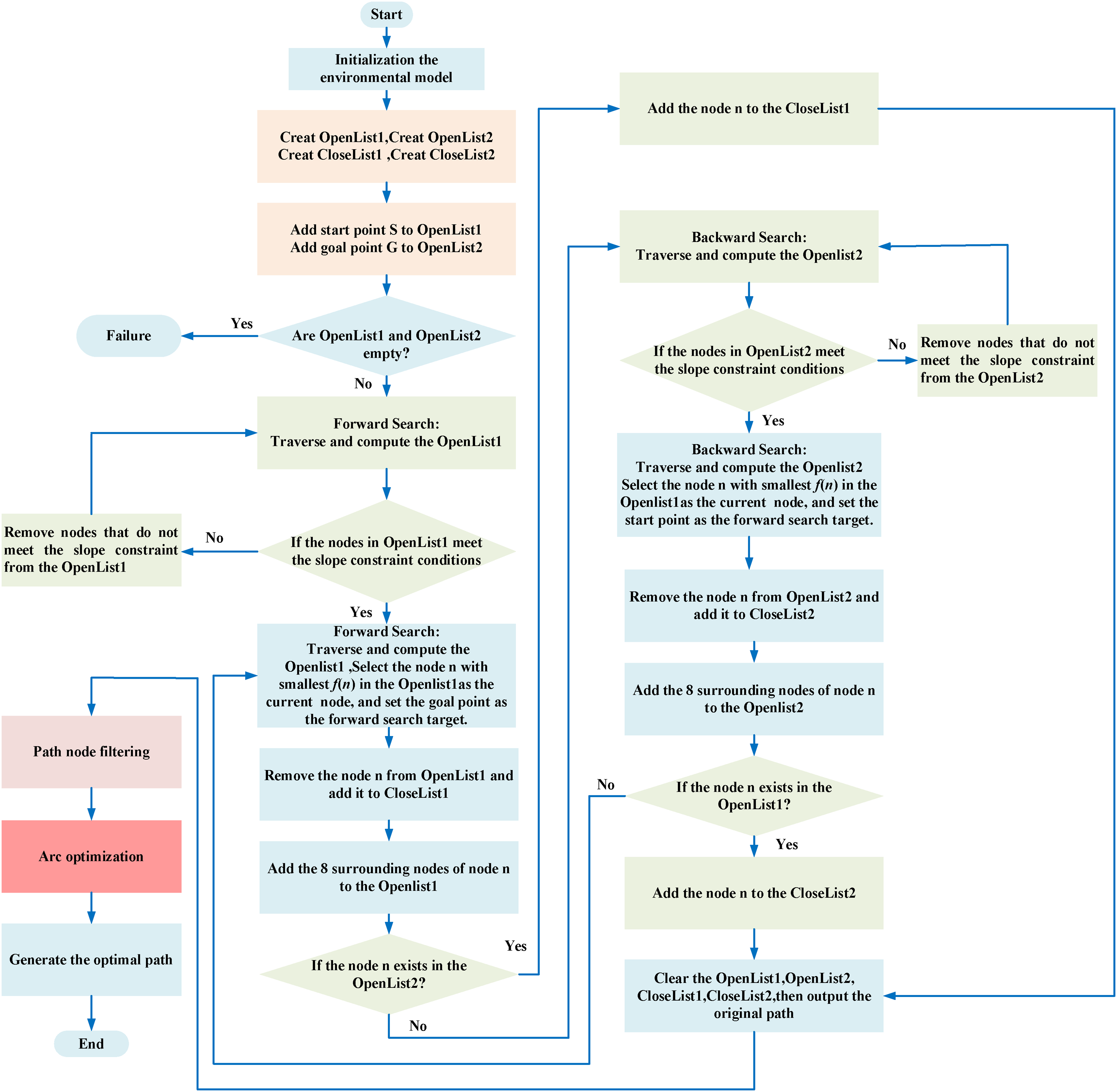
The flow chart of the improved A* algorithm.
The traditional A* algorithm simply uses the geometric path length as the actual cost, which results in large memory consumption and long computation time. Especially in environments like construction sites with long-distance and uneven terrain, the increase in constraint conditions makes the computation time of the algorithm even longer. In order to further enhance the computational efficiency of the A algorithm, a Bidirectional Alternating Search (BAS) strategy has been introduced into the A* algorithm. This strategy, based on the A* algorithm, initiates an alternating search path from the starting point and the target point until the two search paths intersect which can effectively reduce the search time, thereby improving the efficiency of path planning. Theoretically, forward search and backward search will start from the target point and the starting point respectively, and finally meet at the center of the map. However, in practical applications, the search paths may not intersect at the center due to the uneven distribution of obstacles. Therefore, by alternately replacing the current optimal node in the forward and backward openlist, and by switching the target of the forward and backward heuristic functions, it is ensured that the forward path and the backward path meet. Both the forward and backward paths search for 8 adjacent nodes in each expansion. The forward evaluation function targets the current node in the backward direction, as shown in Equation (8). And the backward evaluation function targets the current node in the forward direction, as illustrated in Equation (9). The heuristic functions for forward and backward searches are respectively presented in Equations (10) and (11).


Figure 7 is a schematic diagram illustrating the principle of path planning using the BAS-A* algorithm in a 100 × 100 grid map. When the algorithm starts running, the starting point S and the target point G of the path are used as the initial nodes for forward and backward search respectively. During the forward search, with S as the starting point and G as the target, the optimal forward node
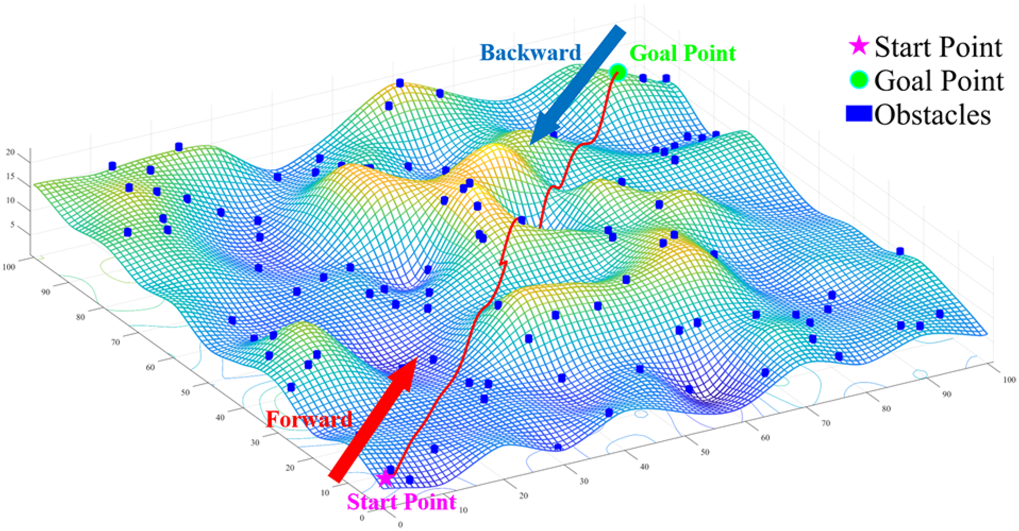
Schematic diagram of the search process using the BAS-A* algorithm.
The pseudo code of the BAS-A* algorithm is as follows:
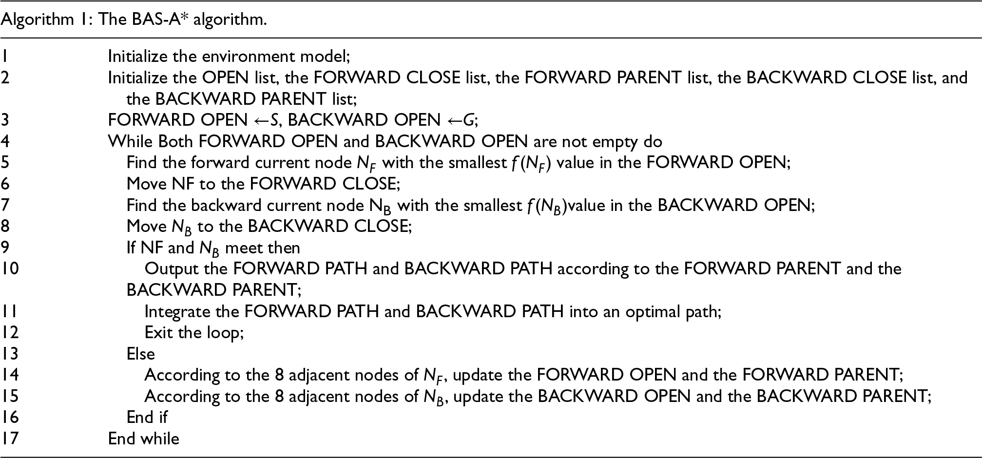
Since the OpenList requires frequent insertions, deletions, updates, and retrievals, a min-heap is employed as its container. The space complexity of the min-heap is O(N), while its time complexity is O(NlogN). On the other hand, the CloseList, which involves frequent insertions and lookups, utilizes a hash table as its data structure. The space complexity of the hash table is O(N), and its overall time complexity is O(N).
It is worth noting that the calculation method of the BAS-A* algorithm is not to calculate the path from the current point to the end point, but to plan the path from the current point to the point with the smallest value in the openlist on the other side. This ensures that the paths in both forward and backward directions will definitely intersect. In addition, the BAS-A* algorithm does not need to ensure that the forward and backward directions are synchronized, and it allows one direction to be faster than the other. The openlist on both sides prioritizes processing the one with fewer nodes each time, which can ensure that the total number of nodes searched in the end will be reduced.
To verify the effectiveness of the BAS-A* algorithm, a simulation experiment was conducted in MATLAB 2022b. In 100 × 100 elevation grid maps, three different terrains were set up and 100 obstacles were randomly arranged on each terrain. Then, collision-free paths were generated in the maps, where the red represents the path of the BAS-A* algorithm, and the yellow represents the path of the A* algorithm. The generated paths are shown in Figure 8.
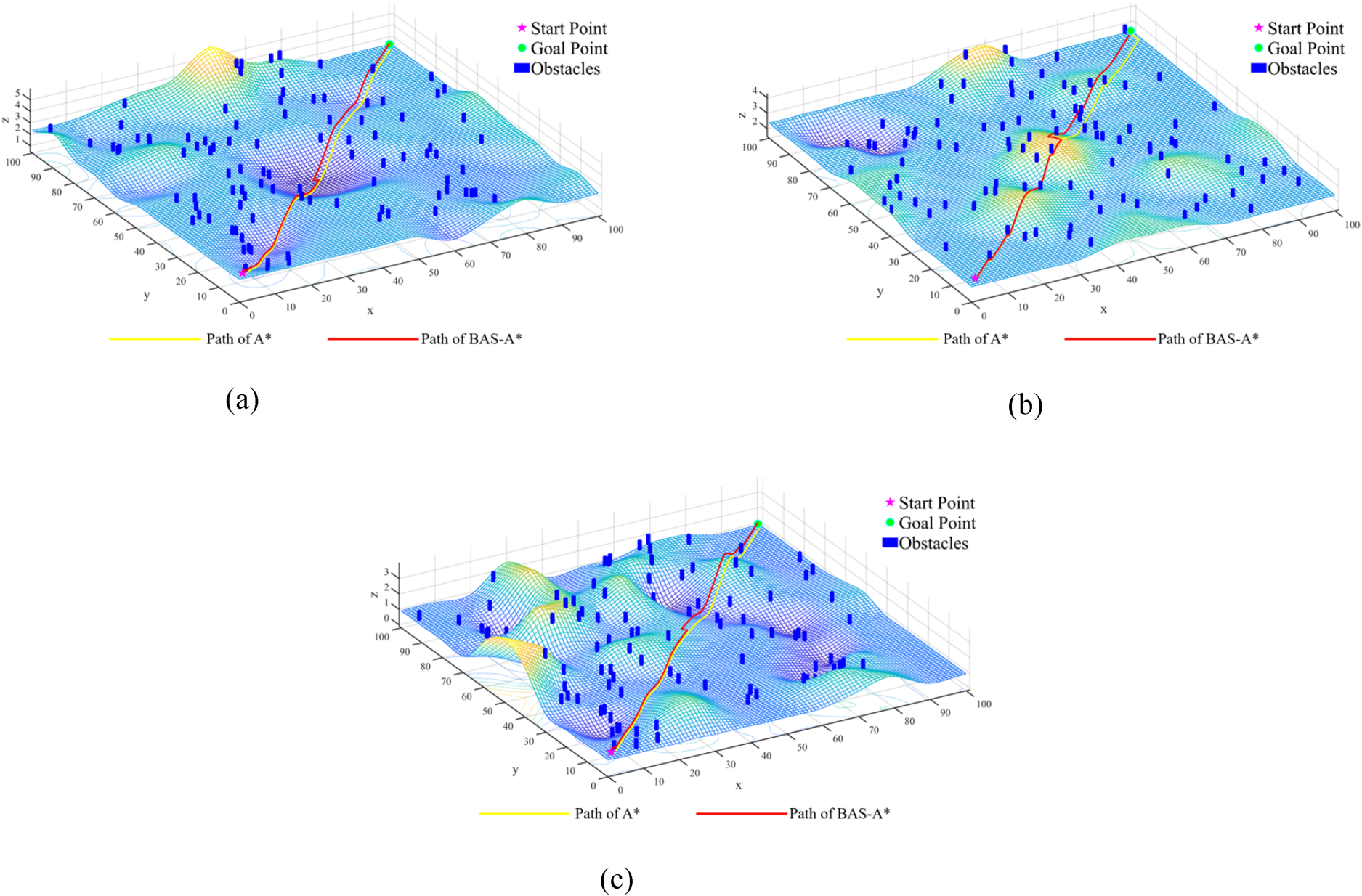
The simulation results of A* algorithm and BAS-A* algorithm on map1-map3. (a) Path of A* and BAS-A*on map1. (b) Path of A* and BAS-A*on map2. (c) Path of A* and BAS-A*on map3.
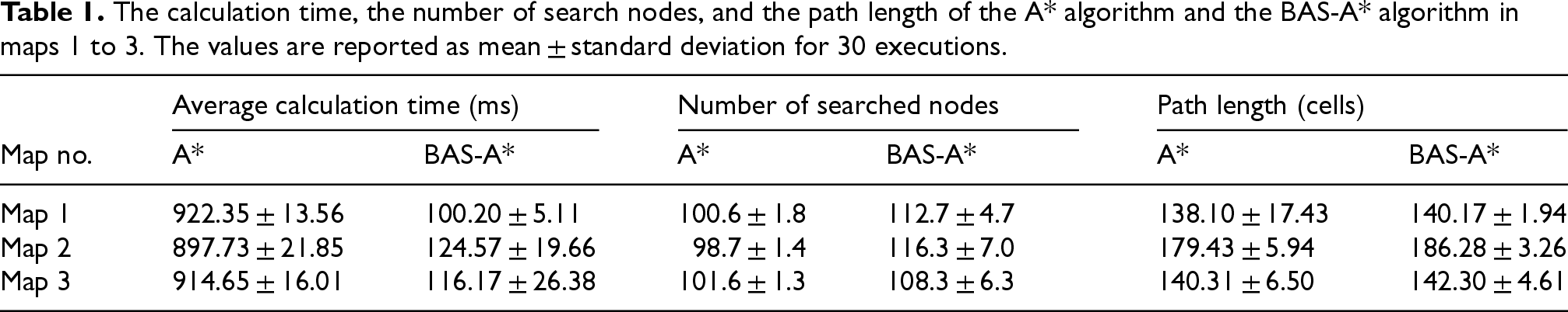
To make the test results more representative, 50 tests were conducted on each map, and the 100 obstacles were randomly redeployed in each test. Table 1 presents the results of 50 simulation experiments of the A* algorithm and the BAS-A* algorithm on three different terrains. The results show that, in these three maps, compared to the traditional A* algorithm, the BAS-A* algorithm increases the number of search nodes by 12.48%, 18.67%, and 7.23%, while the path length remains almost unchanged. Despite this, the BAS-A* algorithm reduces the computation time by 89.14%, 86.12%, and 87.30% respectively, highlighting the effectiveness of the bidirectional alternating search strategy in enhancing the speed of the algorithm.
The calculation time, the number of search nodes, and the path length of the A* algorithm and the BAS-A* algorithm in maps 1 to 3. The values are reported as mean ± standard deviation for 30 executions.
It is worth noting that the BAS-A* algorithm can effectively reduce the time of path planning. However, when the forward and backward paths meet, as can be clearly seen in the overhead view in Figure 9, the BAS strategy sometimes unnecessarily searches nodes back and forth, and may even search more nodes than the A* algorithm. This leads to path duplication, affecting the efficiency of path planning and the control of robot movement.
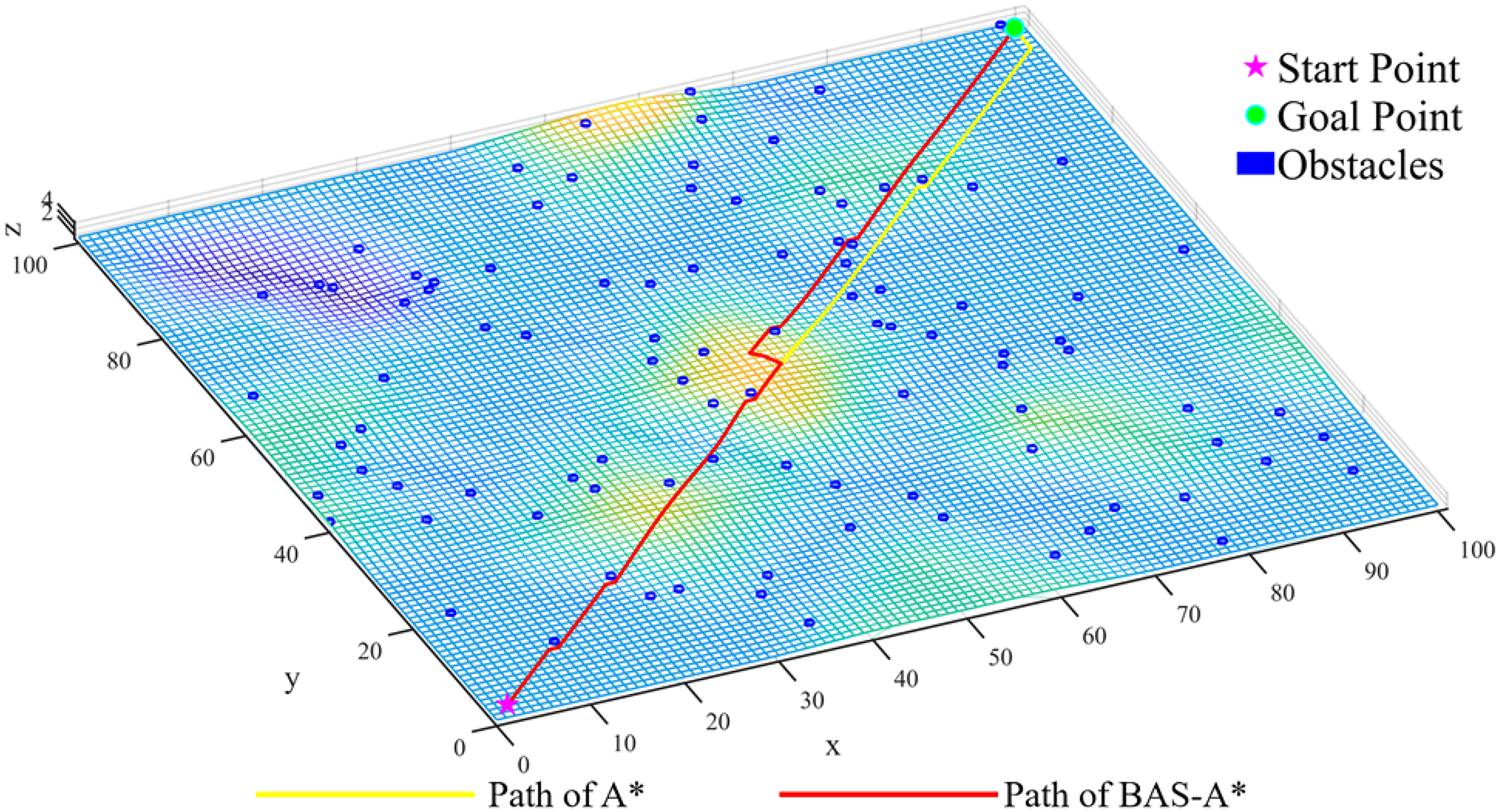
Overhead view of the path generated by the BAS-A* algorithm.
The challenges posed by the aforementioned BAS strategy can be addressed through the implementation of path critical node filtering within the planned trajectory. The filtering of path nodes can effectively reduce the quantity of critical nodes in the path planning facilitated by the BAS-A* algorithm, thereby avoiding path redundancy and diminishing the frequency of directional changes. Such optimization yields paths that are more conducive to the effective control of mobile robots during real-time navigation.
Figure 10 illustrates the selection process of key path nodes, where P3, P4, P7, and P9 are the critical path nodes selected by the filtering algorithm. Specifically, all path nodes planned by the improved BAS-A* algorithm are extracted (as shown in Figure 10(a)), namely S, P1, P2, P3…P16, G. Starting from the origin point S, S is connected to P1. If there is no obstacle between S and P1, then S is connected to P2, and so on, until there is an obstacle between S and Pk (k = 3, 4, …, n). Then, Pk−1 is connected to S, and the redundant nodes in the middle (all path nodes between node S and node Pk−1) are removed to update the path. This operation is repeated starting from node Pk until the target point G is searched, resulting in the red path shown in Figure 10(b). Filtering path nodes can effectively eliminate path redundancy, reduce the number of search nodes, shorten the path length, and decrease the number of turns.
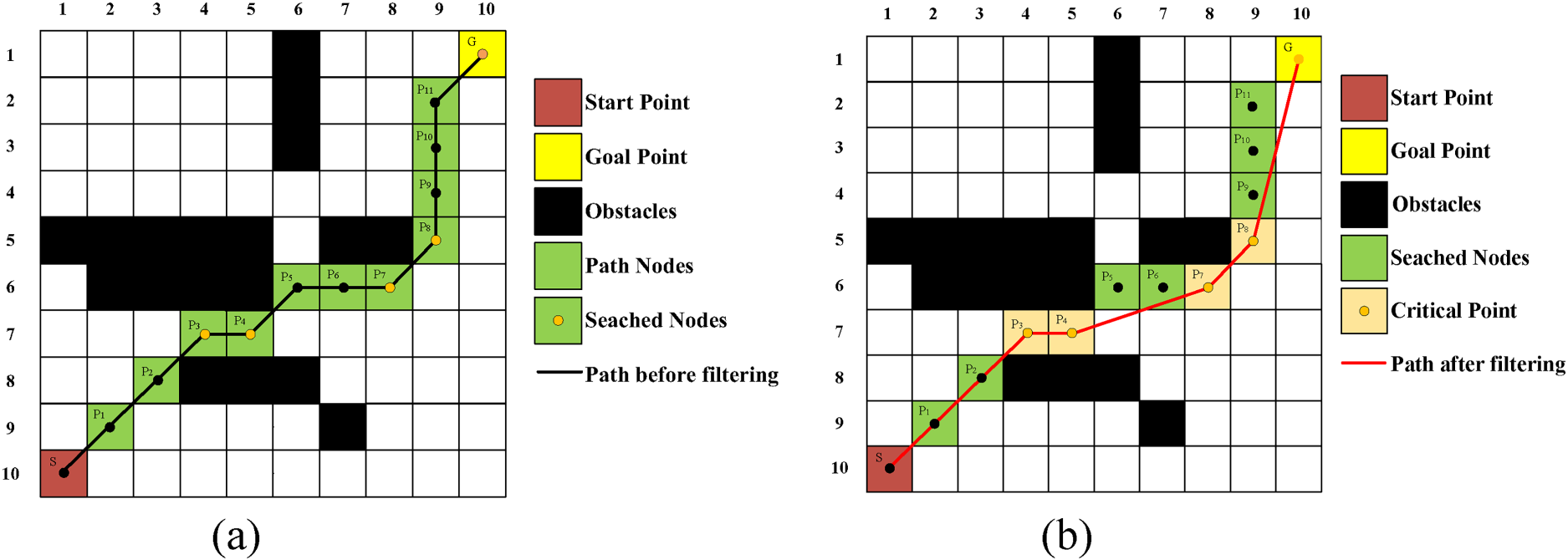
The comparison of path before and after node filtering. (a) The path before filtering. (b) The path after filtering.
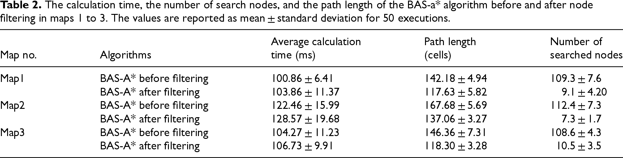
Figure 11 and Table 2 respectively present the simulation results and information of the BAS-A* algorithm on different environmental maps, before and after node filtering. Compared with the unfiltered BAS-A* algorithm, the node-filtered BAS-A* algorithm, in Maps 1 to 3, has slightly increased computation times by 2.97%, 4.99%, and 2.36% respectively. However, it has shortened path lengths by approximately 17.27%, 18.26%, and 19.17%, and reduced the number of nodes by 91.67%, 93.51%, and 90.33% respectively. This demonstrates that the introduction of node filtering significantly reduces redundant nodes in the BAS-A* algorithm and shortens path lengths. The improved paths better meet the requirements of optimal path planning for mobile robots.
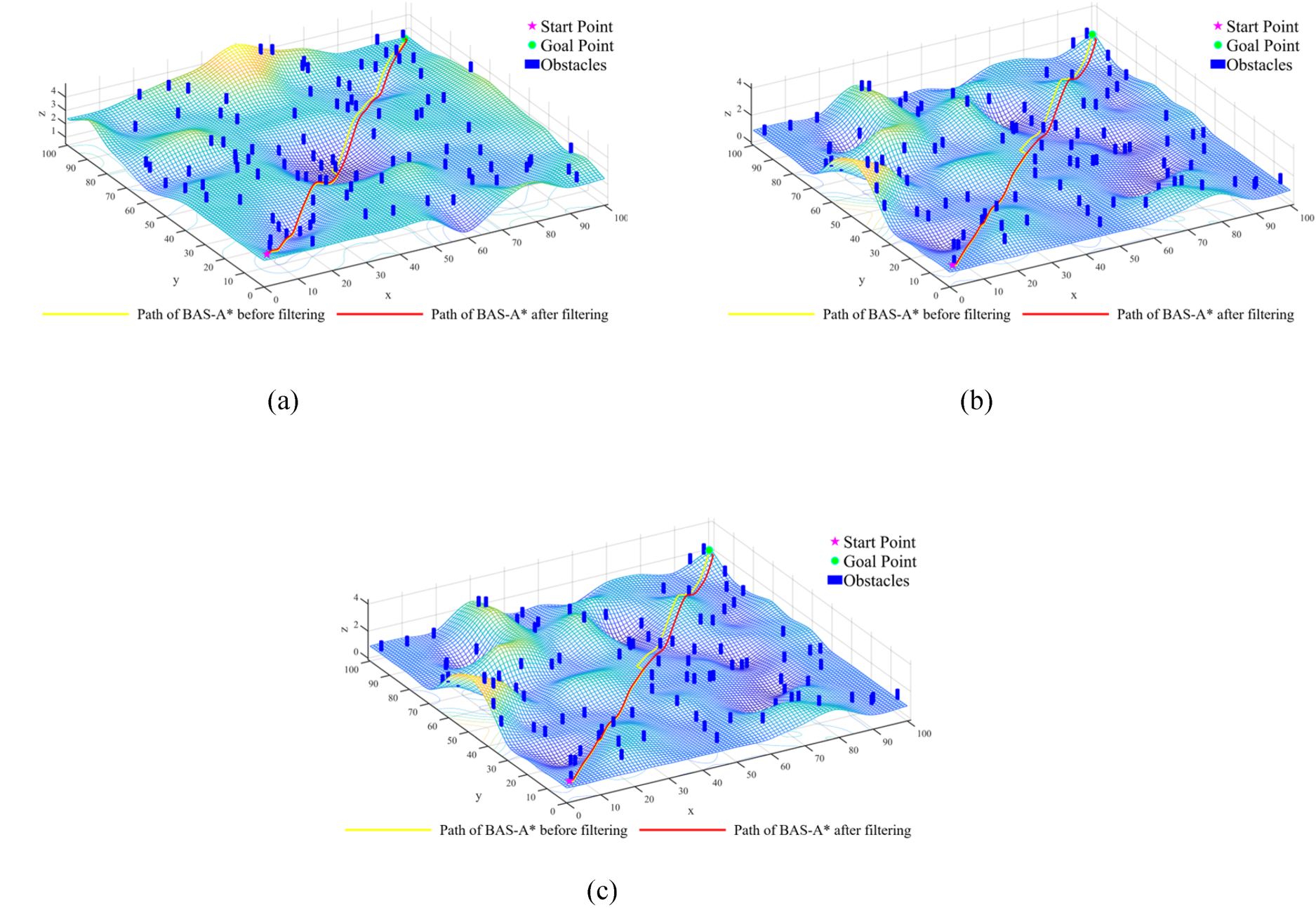
The comparison of paths before and after node filtering in map1-map3 for the BAS- A*. (a) The comparison of paths before and after node filtering in map 1 for the BAS- A*. (b) The comparison of paths before and after node filtering in map 2 for the BAS- A*. (c) The comparison of paths before and after node filtering in map 3 for the BAS- A*.
The calculation time, the number of search nodes, and the path length of the BAS-a* algorithm before and after node filtering in maps 1 to 3. The values are reported as mean ± standard deviation for 50 executions.
The traditional A* algorithm does not take into account the size of the mobile robot, instead treating it as a point mass. In practical path planning, the planning of paths in three-dimensional terrain needs to consider not only the length of the path but also impose restrictions on path safety.
Path safety is primarily reflected in the issue of slope, where the climbing slope of the planned path cannot exceed the maximum climbing slope 
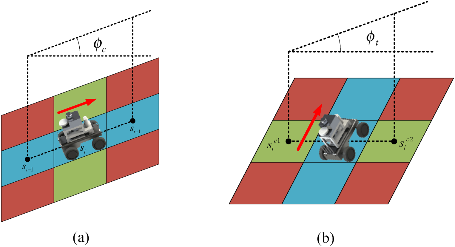
Schematic diagram of the maximum climbing slope
In the formula, n is the total number of nodes in the planned path,
In addition to the climbing angle, when the lateral tilt angle is large, it can also pose a threat to the safety of the mobile robot. The tilt angle of the planned path cannot exceed the maximum tilt angle 
The improved A* algorithm incorporates the robot's slope constraints by performing the following operations: when searching the neighboring nodes of the current node, the algorithm first evaluates whether these nodes satisfy the constraints of the maximum climb angle and the maximum tilt angle. If the conditions for the maximum climb angle
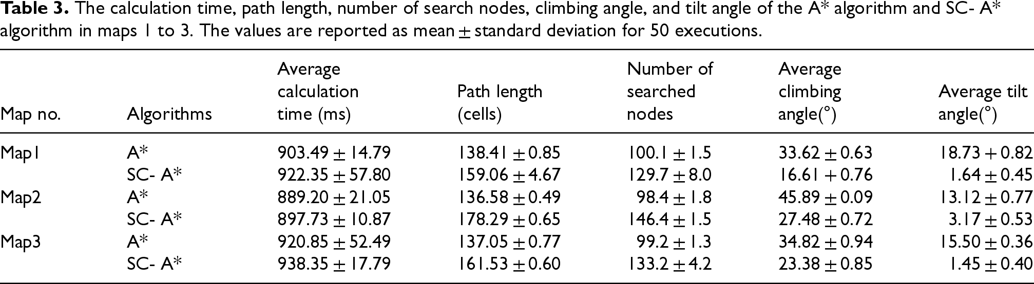
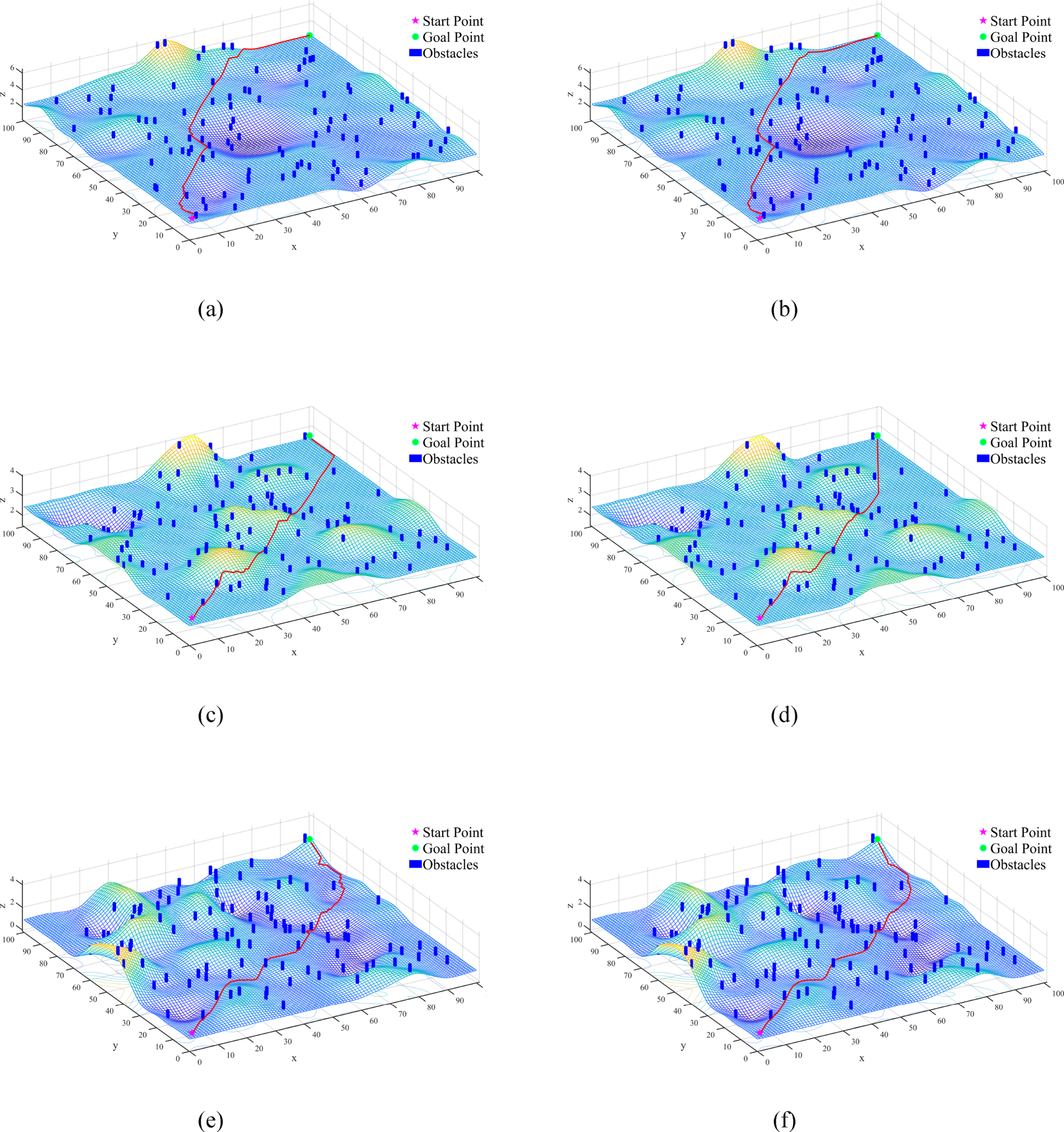
To validate the effectiveness of slope constraints in avoiding areas with large slopes, the traditional A* algorithm and the A* algorithm with added slope constraints (abbreviated as SC- A*) were each tested 50 times for path planning on three different maps. The simulation results from Figure 13 show that, on the three different maps, compared to the traditional A* algorithm, the paths planned by the SC-A* algorithm noticeably avoid areas with larger slopes, and the climbing angle and tilt angle are significantly reduced. The data in Table 3 shows that the climbing angles have been reduced by 50.59%, 40.12%, and 32.85% respectively, and these angles are all kept below 30°. The tilt angles have been reduced by 91.24%, 75.84%, and 90.65% respectively, and are kept below 10°. This ensures the safety of the robot during movement. However, it is worth noting that although the SC-A* algorithm has significantly improved safety in path planning, the path length has increased by 14.92%, 30.54%, and 17.86% respectively, and the number of search nodes has increased by 29.57%, 48.78%, and 34.27% respectively. The increase in algorithm calculation time is relatively minor, at 2.09%, 0.96%, and 1.90% respectively.
The simulation results of the A* algorithm and sc-A* algorithm. (a) Path of A* on map1. (b) Path of SC- A* on map1. (c) Path of A* on map2. (d) Path of SC- A* on map2. (e) Path of A* on map3. (f) Path of SC- A* on map3.
The calculation time, path length, number of search nodes, climbing angle, and tilt angle of the A* algorithm and SC- A* algorithm in maps 1 to 3. The values are reported as mean ± standard deviation for 50 executions.
In practical path planning, the planned path and its curvature should be continuous, and the path should be easy for the motion control of mobile robots. Traditional A* algorithms have many path turning points, which pose a significant challenge to the load of the robot's motor and greatly affect the robot's work efficiency. The A* algorithm after node filtering has fewer turns and smaller turning angles than the traditional A* algorithm, but the planned path is still not smooth. In order to better meet the motion control of mobile robots, reduce the frequency and amplitude of motor start and stop, thereby improving the life and safety of robots, it is necessary to smooth the motion trajectory. Therefore, this article uses Bézier curves to optimize the trajectory.
The Bézier curve, developed from the Bernstein polynomial, is a type of parametric curve. Due to its simple control, it is widely used in practical engineering, mainly for smoothing line segments. Using Bézier curves to handle the corners generated by the A* algorithm can make the running path of mobile robots smoother. The Bézier curve is determined by a set of vectors called control points. Connect the given control points to form a control polygon, approximate this polygon with the Bézier curve formula, and get the Bézier curve. In the Bézier curve, n + 1 feature points can define an nth-order Bézier curve. The parametric equation of the point on the Bézier curve is:


Although the fourth-order Bézier curve can accurately describe complex curves by using more control points (a total of five: the starting point, the ending point, and three intermediate points), it may be more difficult to handle compared to the third-order curve. The calculation and drawing of the fourth-order Bézier curve may be more time-consuming, and sometimes the optimized path may collide with obstacles after optimization. Therefore, this paper uses the third-order Bézier curve to smooth the trajectory, as shown in Figure 14. When 
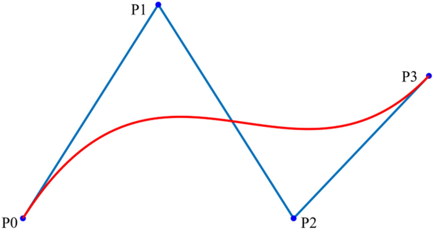
Schematic diagram of third-order Bézier curve.
In order to smooth the path through Bézier curves and make it closer to the path after filtering, a midpoint and an eighth point near the key path node are added between every two key path nodes, and this series of path nodes are set as the control nodes of the Bézier curve. Figure 15 shows the comparison before and after the arc optimization of the path planned by the SC- A* algorithm. It can be clearly seen from the enlarged view of Figure 16 that the optimized path has been smoothed at the corners, ensuring that the robot operates smoothly during operation, reducing motor wear, avoiding imbalance in the robot itself, which is more conducive to practical control, and improving the actual motion efficiency of the mobile robot.
Comparison of the path of SC-A* on Map1-3 before and after arc optimization. (a) The Path of SC- A* on Map1 before Arc Optimization. (b) The Path of SC- A* on Map1 After Arc Optimization. (c) The Path of SC- A* on Map1 before Arc Optimization. (d) The Path of SC- A* on Map1 After Arc Optimization. (e) The Path of SC- A* on Map1 before Arc Optimization. (f) The Path of SC- A* on Map1 After Arc Optimization.
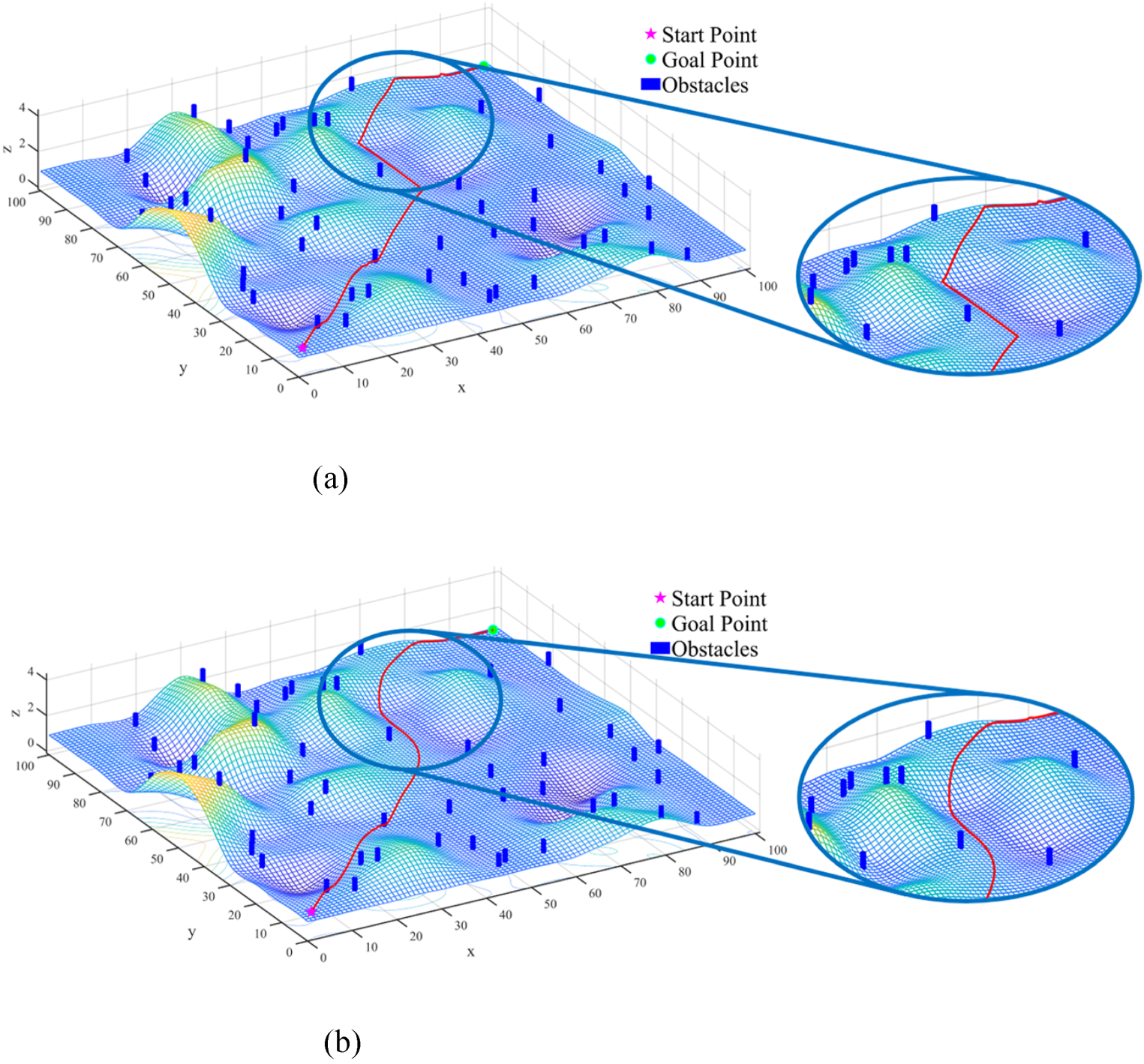
Enlarged view of the path before and after Arc optimization. (a) Enlarged View of the Path of SC- A* before Arc Optimization. (b) Enlarged View of the Path of SC- A* after Arc Optimization.
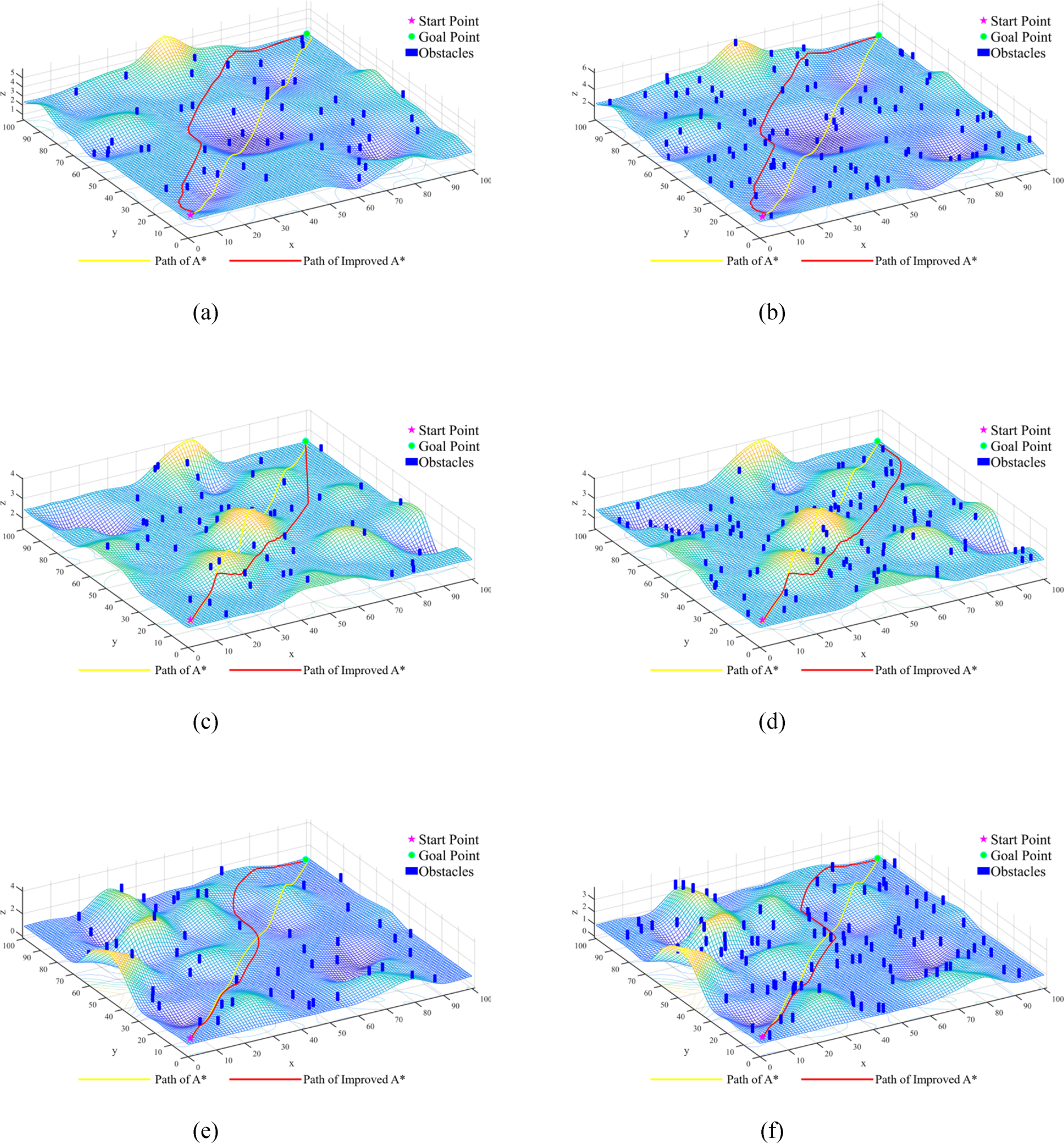
The path of A* and improved A* on map1 to map3. (a) Path of A* and Improved A* on map1 with 50 barriers. (b) Path of A* and Improved A* on map1 with 100 barriers. (c) Path of A* and Improved A* on map2 with 50 barriers. (d) Path of A* and Improved A* on map2 with 100 barriers. (e) Path of A* and Improved A* on map3 with 50 barriers. (f) Path of A* and Improved A* on map3 with 100 barriers.
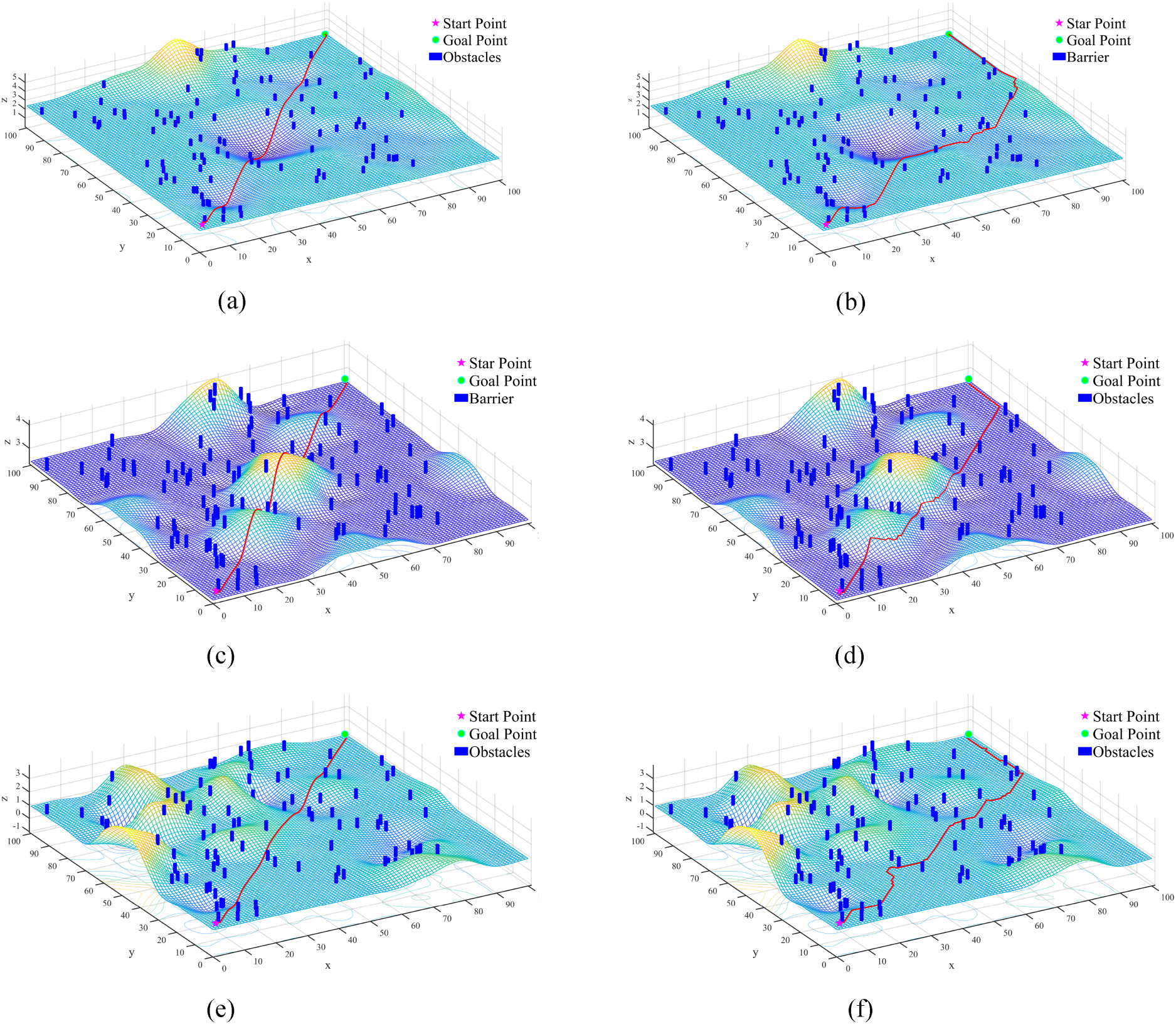
The effectiveness of each individual improvement has been demonstrated in Chapter 3. To validate the effectiveness of the Improved A* algorithm, which integrates all the aforementioned improvements, this study designed three different terrains (namely, concave terrain, convex terrain, and rugged terrain) on a 100 × 100 elevation grid map. Each terrain was set up with 50 and 100 obstacles respectively, resulting in six different maps for experimental validation. To compare the A* algorithm with the Improved A* algorithm, 50 simulation experiments were conducted on each map, yielding the average values for algorithm calculation time, average path length, number of key nodes, climbing angle, and tilt angle.
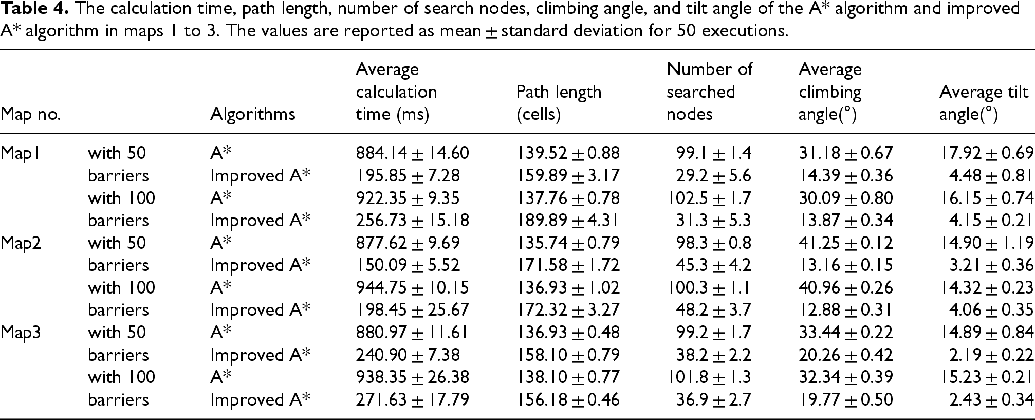
From the simulation results in Figure 17, it can be seen that compared to the A* algorithm, the Improved A* algorithm plans paths that avoid areas with larger slopes on all maps. Additionally, the positions of path turns are smoother. From the experimental results in Table 4, in Maps 1 to 3 with different terrains, compared to the A* algorithm, the Improved A* algorithm reduces the algorithm calculation time by 71.05% to 82.90%, the number of key nodes by 51.94% to 70.53%, and the climbing angle by 38.87% to 68.55% (all below 30°), and the tilt angle by 71.65% to 85.29% (all below 10°), under the premise that the path length increases by 14.6% to 37.84%. Under the same terrain, compared to the situation with 50 obstacles, when there are 100 obstacles, the search time of the A* algorithm will increase by about 4.32% to 7.65%, and the search time of the Improved A* algorithm will increase by about 12.76% to 32.22%. The changes in path length, search nodes, climbing angle, and tilt angle can almost be ignored.
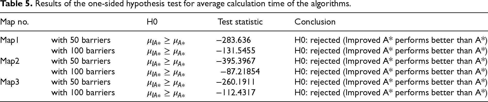
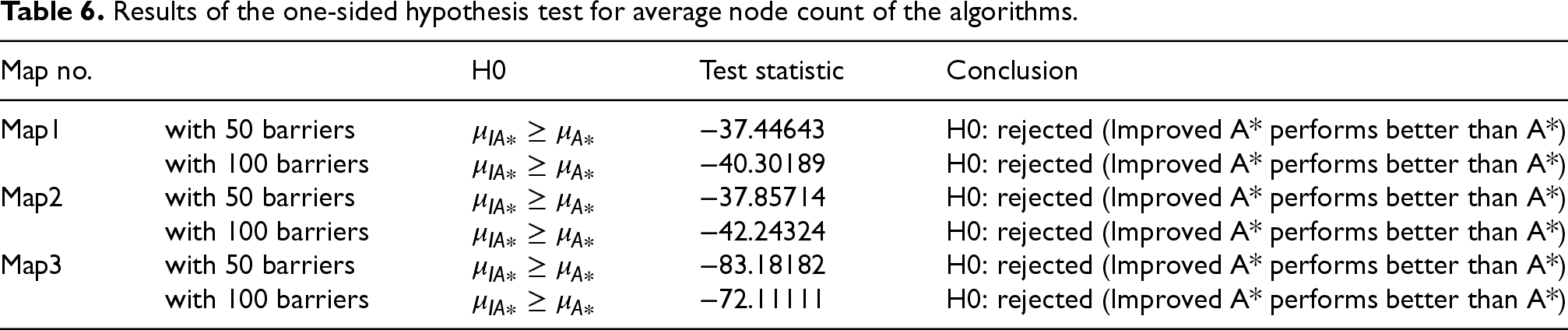
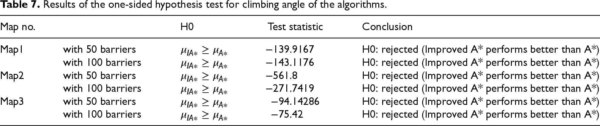
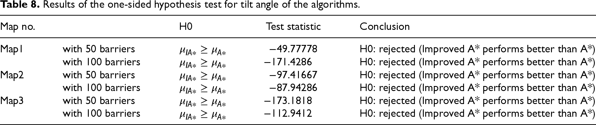
In order to further compare the performance of the Improved A* algorithm with the A* algorithm, the following hypothesis test was conducted. The hypothesis test is a one-sided large sample population mean hypothesis test, with the null hypothesis H0 defined as: the A* algorithm is statistically superior to the Improved A* algorithm. The significance level a = 0.01 was chosen, and the rejection region was
To facilitate a more intuitive comparison between the original and improved algorithms, an uneven terrain, as depicted in Figure 18, was constructed in the Gazebo physics simulation software. This setup was used to further validate the effectiveness of the improved A* algorithm.
The robot primarily acquires external environmental information through a stereo depth camera and uses the Elevation_mapping algorithm for localization and the construction of an elevation grid map. Considering the actual dimensions of the mobile robot and the accuracy required for the grid map, the ground was divided into an elevation grid map with a resolution of 100 × 100 for the experiment. The elevation grid map generated by the Elevation_mapping algorithm is shown in Figure 19.
The calculation time, path length, number of search nodes, climbing angle, and tilt angle of the A* algorithm and improved A* algorithm in maps 1 to 3. The values are reported as mean ± standard deviation for 50 executions.
The calculation time, path length, number of search nodes, climbing angle, and tilt angle of the A* algorithm and improved A* algorithm in maps 1 to 3. The values are reported as mean ± standard deviation for 50 executions.
Results of the one-sided hypothesis test for average calculation time of the algorithms.
Results of the one-sided hypothesis test for average node count of the algorithms.
Results of the one-sided hypothesis test for climbing angle of the algorithms.
Results of the one-sided hypothesis test for tilt angle of the algorithms.
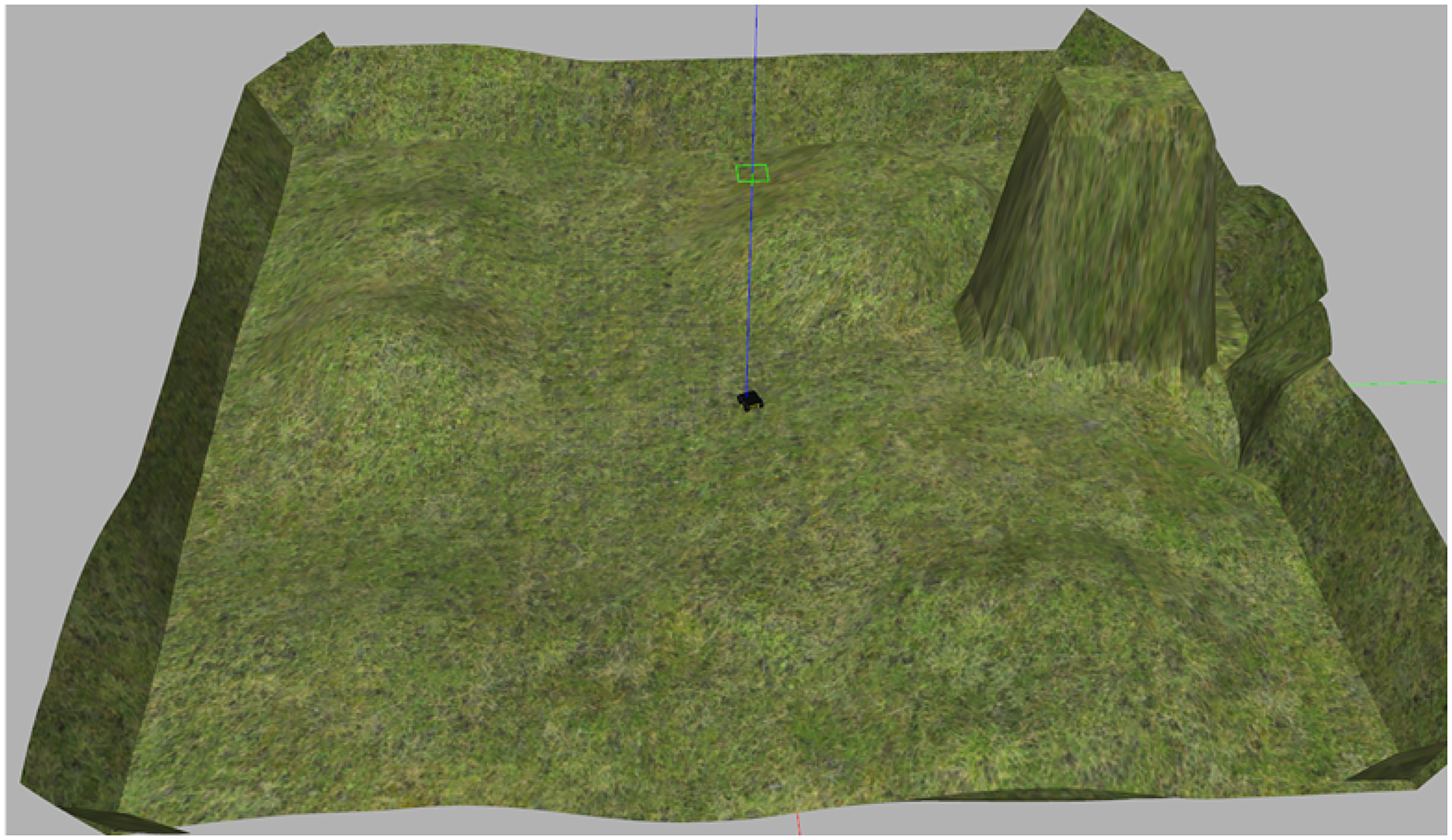
Uneven terrain physical simulation model.
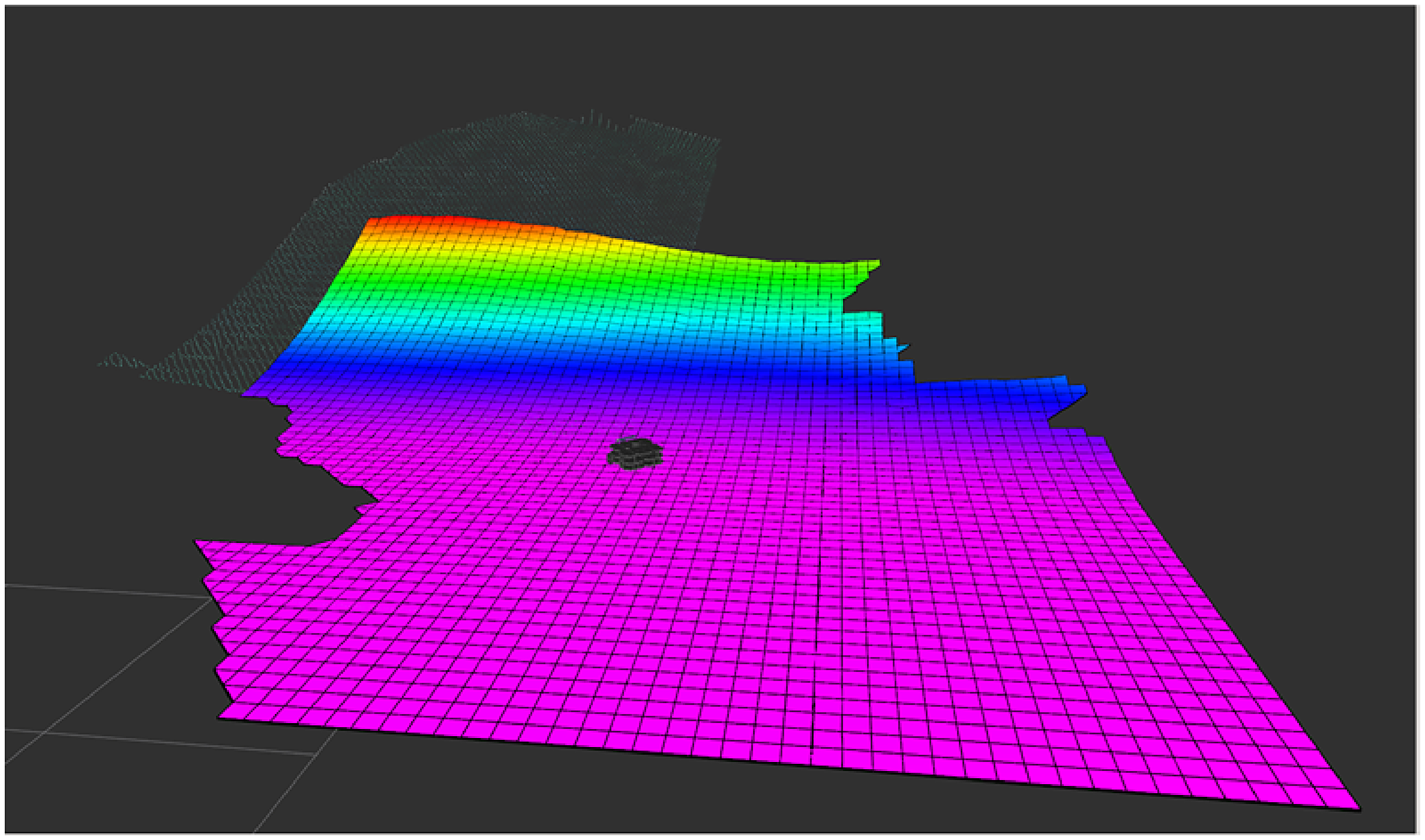
Elevation_mapping algorithm constructs elevation raster map.
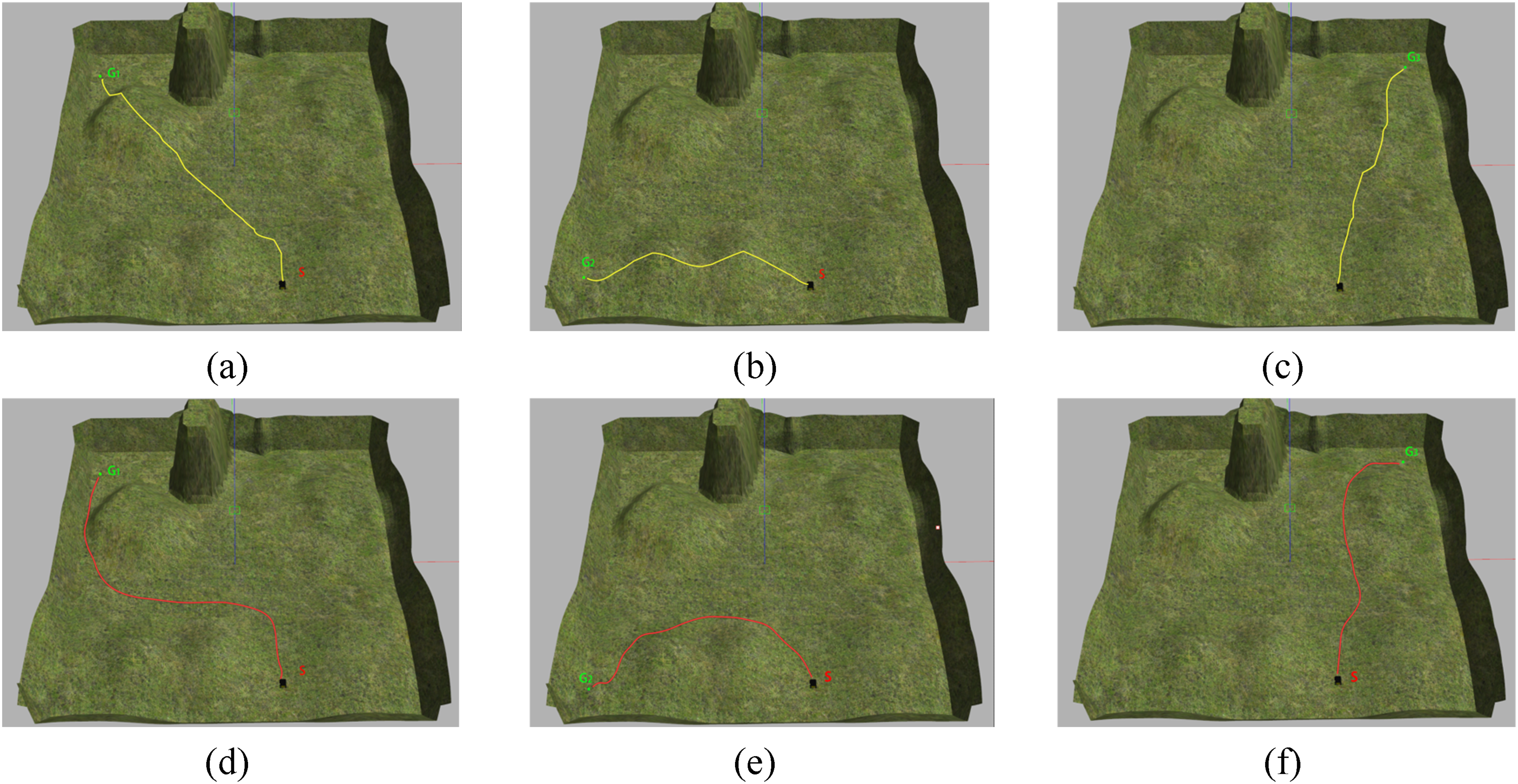
Comparison of A* and improved A* algorithm planning paths on simulated uneven terrain.
Using the same starting point and three different target points, the path planning results of the A* algorithm and the Improved A* algorithm are shown in Figure 20. As illustrated by the yellow paths in Figure 20(a-(c)), the paths generated by the A* algorithm exhibit issues such as sharp turns, numerous turning nodes, and lack of smoothness. Additionally, the algorithm fails to avoid areas with steep slopes that the robot cannot traverse, which could prevent the robot from reaching the target point in real-world environments. In contrast, the red paths shown in Figure 20(d-(f)) represent the paths planned by the Improved A* algorithm, which successfully avoids steep slope areas that the robot cannot navigate and produces smoother paths, facilitating better motion control of the robot.
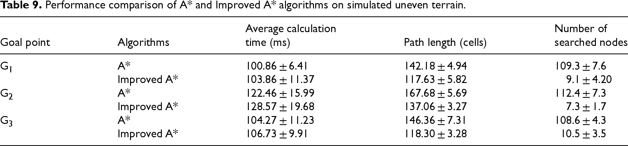
Table 9 presents the average path planning time, path length, and number of nodes for both the A* algorithm and the Improved A* algorithm across different target points. The data indicate that, compared to the A* algorithm, the Improved A* algorithm reduces path planning time by 51.87% to 76.60% and decreases the number of nodes by 86.08% to 92.10%.The experimental results demonstrate that the Improved A* algorithm effectively completes the robot's path planning tasks. Moreover, the Improved A* algorithm outperforms the A* algorithm in terms of path optimization capability, planning efficiency, and path safety.
By using the A* algorithm for path planning of mobile robots, a collision-free path connecting the start and end points can be obtained. However, this algorithm has disadvantages such as long computation time, non-smooth paths, and unsuitability for rugged construction sites. To solve these problems, this paper proposes an Improved A* algorithm. This algorithm introduces a bidirectional alternating search strategy, which improves the efficiency of the search path. By filtering the path nodes, it not only overcomes the problem of path duplication caused by bidirectional search, but also reduces the number of key nodes, thereby reducing the difficulty of the search. By introducing slope angle constraints and tilt angle constraints, the search path is restricted to areas with smaller slopes. Finally, the path is fitted with a Bézier curve to obtain a smooth path.
Performance comparison of A* and Improved A* algorithms on simulated uneven terrain.
Simulation results in elevation grid maps with different terrains and varying numbers of obstacles show that the Improved A* algorithm can significantly enhance the speed of path planning, reduce the number of key nodes in the search, and simultaneously decrease the climbing angle and tilt angle of the path. This makes the planned path practically feasible, ensuring the safety of the robot during movement. Furthermore, the path generated by the Improved A* algorithm is smoother, which is more conducive to the motion control of the robot.
However, the Improved A* algorithm only considers the algorithm's runtime and does not account for the time and energy costs associated with the robot adjusting its posture during actual movement. Additionally, the impact of dynamic obstacles has not been taken into consideration. Future work will involve integrating data from additional sensors, such as LiDAR and cameras, to explore how robots can perceive and dynamically model complex construction environments in real-time, thereby providing more accurate information for path planning. Efforts will also be made to combine the Improved A* algorithm with other algorithms to enable its application in multi-robot system path planning, allowing robots to share path planning information and environmental data, and achieve more advanced collaboration.
Footnotes
Authors contributions
Funding
This work is supported by the Key Research and Development Program of Shaanxi under grant number (No. 2024GX-ZDCYL-02-04), the Shaanxi Provincial Technical Innovation Guidance Special (Fund) Project under grant number (No. 2023GXLH-064), and the Technology R & D project of XAUAT Engineering Technology Co., Ltd. under grant number (No. XAJD-YF24N008).
Conflict of interest
The authors declared no potential conflicts of interest with respect to the research, authorship, and/or publication of this article.