
Abstract
The existing blast tests of concrete-filled steel tubular are mainly on the dynamic behaviors of concrete-filled steel tubular at ambient temperature. ANSYS codes are used to simulate the temperature distribution of reactive powder concrete-filled steel tubular, and subsequently an approximate approach is used to estimate the residual strength of reactive powder concrete. Then blast-resistant capacities of four large-scale reactive powder concrete-filled steel tubular columns after exposure to ISO-834 standard fire are experimentally examined. The overpressures of shock wave, displacements, and strains of reactive powder concrete-filled steel tubular columns are recorded by advanced gauges. Influences of fire durations and scaled stand-off distances of explosive charge on dynamic behaviors and failure modes of reactive powder concrete-filled steel tubular columns are discussed. It is shown that reactive powder concrete-filled steel tubular columns retain excellent blast-resistant capacity after exposure to fire. Reactive powder concrete core column can be effectively confined by steel tube, but its blast-resistant capacity decreases as explosive charge or fire duration increases. Failure modes change from bending types to bending-shear types as explosive charge increases, and obvious plastic deformation at the mid-span section can be observed in the reactive powder concrete-filled steel tubular columns with fire duration of 105 min. It is also indicated that the maximum displacement of reactive powder concrete-filled steel tubular columns is more sensitive to fire duration than to explosive charge weight.
Keywords
Introduction
Some special structures are designed in order to resist exceptional events. For instance, military buildings, protective engineering, or strategic constructions may suffer blast loads caused by missiles or other accidents. But, the terrorist attack event of 11 September 2001 has changed the way we consider the reliability of current constructions. The collapsing of the World Trade Center was caused by high temperature after impact. In addition, material properties will degrade after exposure to fire, but most of these constructions are still used as blast-resistant structures. It is necessary to reassess the blast-resistant reliability of structures which have been exposed to accidental fire or high temperature. Concrete-filled steel tubular (CFST) structures are widely used in civil engineering structures, such as high-rise buildings, large-span bridges, and electricity transmission towers due to their excellent performances (Zhao et al., 2010). Reactive powder concrete-filled steel tube (RPC-FST) is a member of CFST and is regarded as a new fire-resistant and blast-resistant composite structure with a series of advantages, such as high strength, high rigidity, good plasticity, and ductility. In recent years, RPC-FST structures are usually used as load-bearing members of some major engineering.
A large number of researches on CFST structures under impact loading have been carried out in recent years. Han et al. (2014) presented a set of new test data for high-strength CFST members subjected to transverse impact, and a finite element analysis (FEA) model was established to analyze the dynamic behavior of high-strength CFST members. Finally, a simplified model was obtained based on a parametric analysis to predict the flexural capacity of CFST members under impact loading. The transverse impact behaviors of square CFST members were studied experimentally by Bambach (2011) and Remennikov et al. (2011). Deng et al. (2012) conducted drop hammer impact tests on simply supported circular CFST beams, and dynamic behaviors of CFST beams under transverse impact loading were investigated. Numerical works on CFST beams under impact loading were carried out by Yousuf et al. (2013), Wang et al. (2013), and Bambach (2011), and some important dynamic behaviors of CFST were presented. The carrying capacity of axial impact was performed experimentally by following researchers. Xiao and Shen (2012) performed similar tests on CFST stub columns with a split-Hopkinson pressure bar (SHPB). A simplified calculation method for the axial strength of CFST was derived. With the RPC-FST, experimental investigation into impact-resistant behaviors of RPC-FST column were conducted by Tian et al. (2008) using the SHPB system, and dynamic responses of the columns under axial impact loading were studied by means of numerical simulation method. Some works as listed below have been carried out on impact strength in condition of high temperature. Huo et al. (2009) studied the axial behavior of CFST columns under the combined effects of impact (impact velocity 12–16 m/s, hammer weight 524.2 kg) and elevated temperature (up to 400°C with duration 40 min), and it turned out that CFST columns have better ductile behavior under impact loading and remain excellent impact-resistant capacity under high temperature. Temperature, impact velocity, impact energy, and steel ratio have remarkable effect on dynamic behaviors of CFST columns, but the influences of axial load level are not noticeable. A series of researches were carried out to investigate the blast resistances of steel or concrete structures in the last decades (Ellis et al., 2014; Nassr et al., 2013; Xu et al., 2014; Wu et al., 2009; Yi et al., 2012), but limited work has been conducted on CFST structures under blast loading, in particular, RPC-FST members after exposure to fire or high temperature. Explosive tests on steel tubular members with and without concrete infill were conducted by Remennikov et al. (2014). The stand-off distances considered in these tests were selected to study the response of these steel sections subjected to contact and very close-range detonations of high explosives, then a simplified approach to predicting the dynamic response of square tubular steel members under the near-field air blast loading was proposed. Behaviors of CFST columns under blast loading were studied numerically by Wu et al. (2013) and Feng et al. (2007), and it was indicated that CFST columns tended to occur shearing failure when subjected to impulsive blast load; in the quasi-static region, however, the column was likely damaged with flexural mode; and in the region of dynamic loading, the failure mode might be a combination of shearing and flexural damage. FEA on dynamic response and damage mode of tube-confined concrete column under explosion was carried out by Du (2013), and the results shown that core concrete was seriously damaged and the circular columns had better blast-resistant capacity than square columns. Multi-hazard-resistant bridge piers with CFST under blast loading were studied experimentally by Shuichi Fujikura et al. (2008), and it was found that prototype bridge CFST columns can be designed to provide both satisfactory seismic performance and adequate blast resistance. Recently, dynamic behaviors and failure modes of concrete-filled steel tubular columns (CSTC) under blast loading were studied experimentally by Li et al. (2013), and it was indicated that bending deformations occur in all CSTC, and the maximum and residual displacements increased with the augment of axial compression ratio or explosive charge weight. A few blast-resistant tests on CFST columns were conducted in the testing site of PLA University of Science and Technology, and four rectangular CFST column specimens were used for blast tests by Zhang et al. (2015b). The tests’ results indicated that CFST columns have good resistance against flexural loads under blast-loading conditions, and therefore, it has the potential to be widely used in these areas where latent blast attacks may occur. A close-range blast-loading tests on concrete-filled double-skin tubes (CFDST) infilled with ultra-high performance fiber-reinforced concrete (UHPFRC) were also carried out at the same testing site (Zhang et al., 2015a, 2015c), and researchers evidenced the excellent performance of CFDST columns under blast loading. In addition, the residual axial capacity of CFDST columns subjected to severe blast loadings was studied.
Blast-resistant mechanisms of RPC-FST columns after exposure to fire are still not clear due to the coupling influences of temperature effect, strain rate effect, and inertial effect. In view of this background, a large-scale blast-resistant test is designed to examine the dynamic behaviors of RPC-FST columns post-fire under near-field explosion, where a constant axial force is applied to the end of column along its axis to simulate the vertical load. The column is defined that the L/D ratio is about 13, where D is the outside diameter of the circular steel tubes and L is the length of column. Under this condition, the behaviors of lateral displacement of RPC-FST column can be studied accurately (Han et al., 2002; Song et al., 2010). Due to the lack of test data for RPC-FST column experimental results after exposure to the ISO-834 standard fire without initial loads, the FEA models are developed to study the temperature distribution. The weighted average method is then used to estimate the residual strength and modulus of elasticity of reactive powder concrete (RPC) steel tube and RPC core after exposure to fire based on the simulation results. The influences of fire duration and scaled stand-off distance on strains, displacements, and failure types of RPC-FST specimens are discussed in detail.
Test programs
Four large-scale specimens including one circular column specimen without fire exposure and three circular column specimens after exposure to fire are prepared, and RPC is used as the core concrete in all column specimens. The fabrication of RPC-FST columns is given in Figure 1 and their dimensions are shown in Figure 2. A series of blast tests are conducted at the large-scale blast-resistant test site, PLA University of Science and Technology in China. The main test parameters include standard fire duration and explosive charge weight.
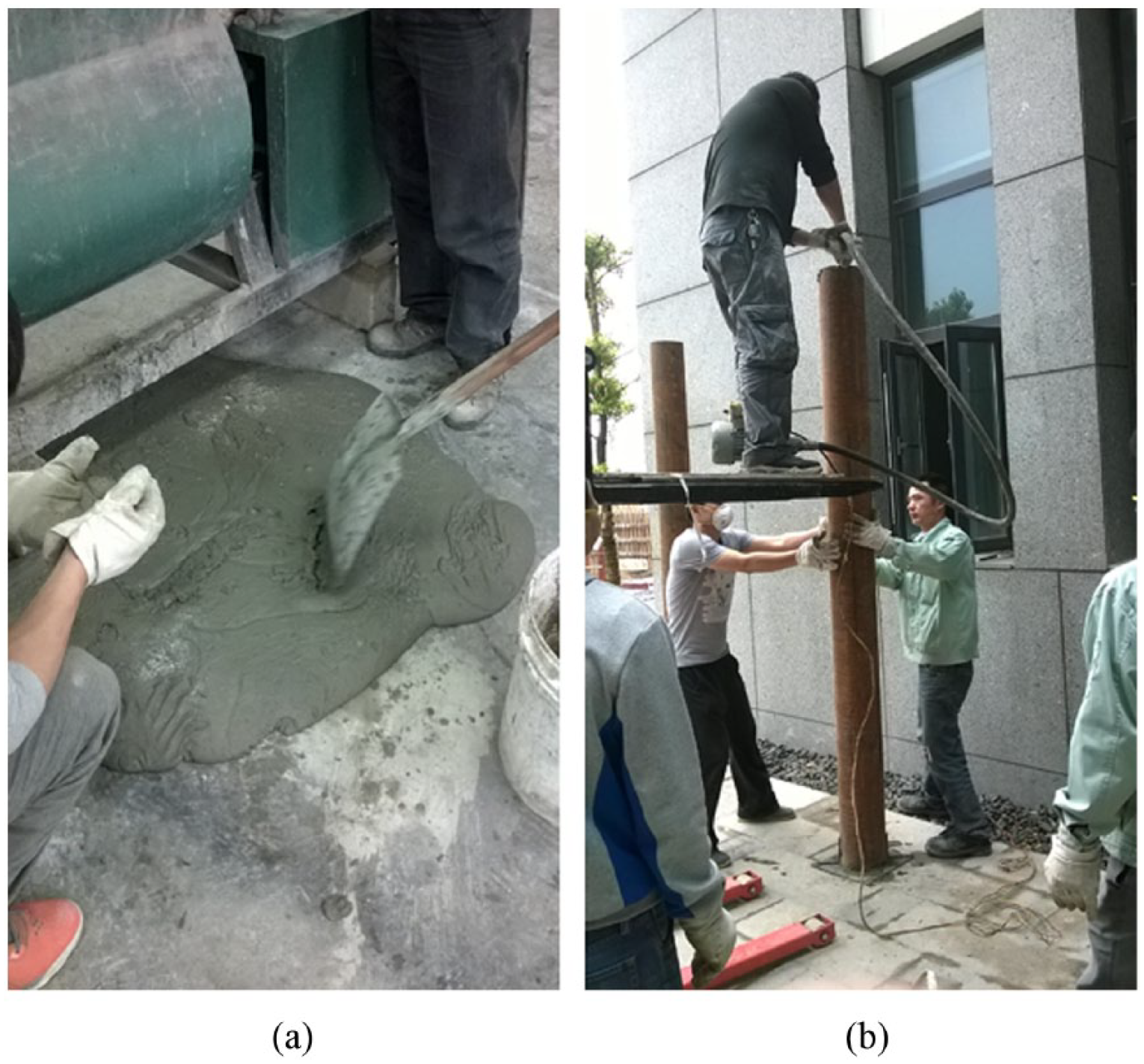
Fabrication of RPC-FST column: (a) RPC mixture and (b) RPC-FST casting.
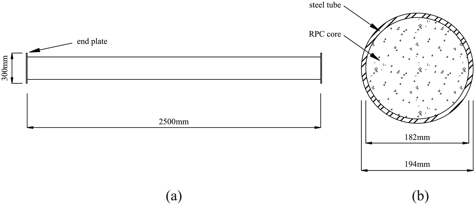
Dimensions of RPC-FST column: (a) RPC-FST column and (b) cross section.
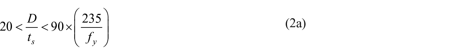
All steel tubes are manufactured from the same batch of steel tubes with diameter D = 194 mm, thickness ts = 6 mm, and length L = 2500 mm. Local bucking of steel tube should be prevented before material failure for CFST member, therefore, a value range of diameter to thickness of steel tube D/ts must be defined. The cross-section classification of the test specimens is determined according to AS 4100-1990 (1998). The cross section can be classified as compact, non-compactor slender based on the section slenderness. For circular cross section, it can be calculated as
where fy is the yield stress of the outer tube. For unfilled circular hollow tube, λ is 50. According to Elchalakani et al. (2001), the plastic limit increases by about 50% for CFST specimens. As a result, λ for the circular RPC-FST columns in this article is determined as 75. Using equation (1), the section slenderness for the circular cross sections is 45.3, which is less than its corresponding plastic limit. In China, diameter-to-thickness D/ts and the length-to-diameter L/D of steel tube (for compressive strength of infilled concrete higher than 60 MPa) are restricted by following formulas

The values of D/ts and L/D evaluated by above equations are approximately 32 and 13, respectively. Therefore, the circular RPC-FST specimens used in this article can be classified as compact section without local bucking occurring.
In order to simulate the actual working condition of column member, each RPC-FST column is constrained by fixed supports, and a constant axial force is applied on the end plate by air cylinder. The blast load is applied by approximate spherical explosive charge, and a near-field air blast is produced in this test. Detailed information about all specimens is summarized in Table 1, where W is the explosive charge weight, H is the stand-off distance, and t is the fire duration. In the present fire exposure test, the fire temperature is assumed to follow the ISO-834 standard fire curve and the fire curve including heating phase and cooling phase as follows.
Detail information of blast test.
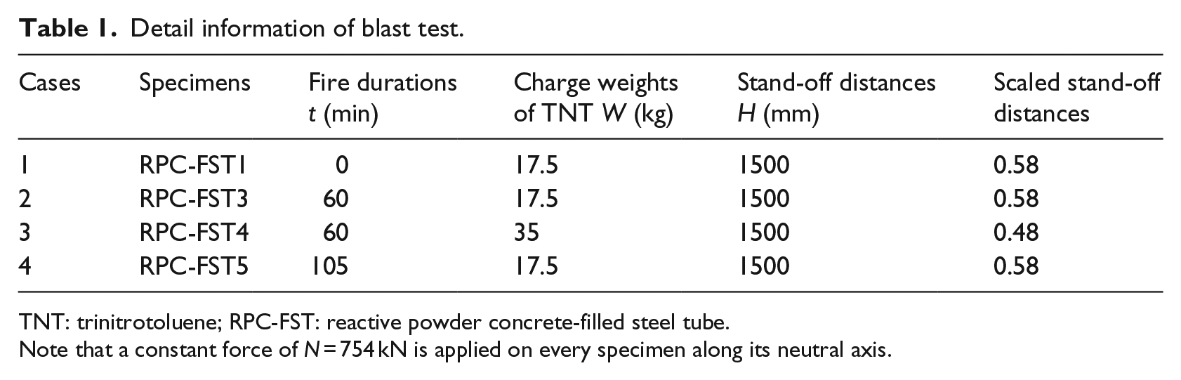
TNT: trinitrotoluene; RPC-FST: reactive powder concrete-filled steel tube.
Note that a constant force of N = 754 kN is applied on every specimen along its neutral axis.
Heating phase:

Cooling phase:
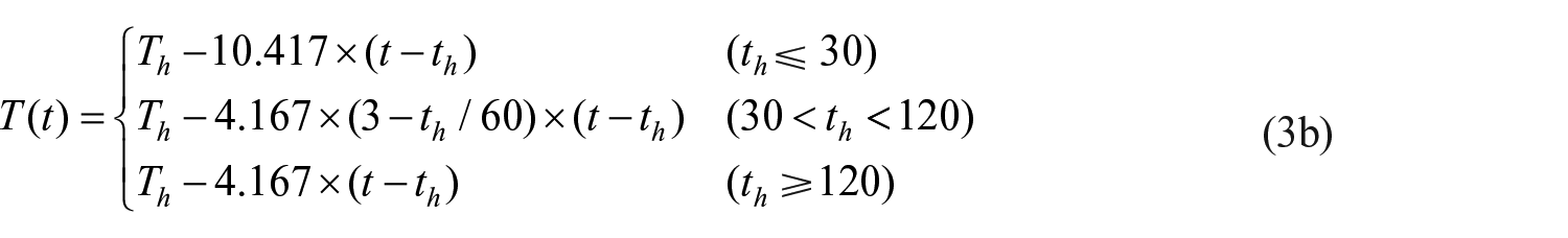
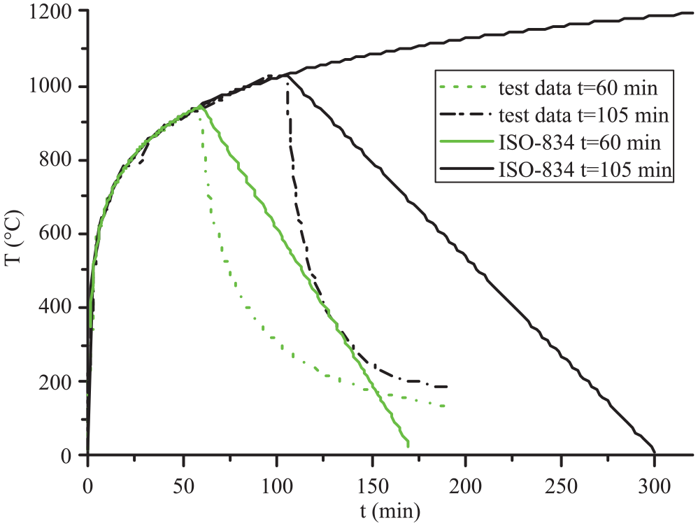
where T(t) is the fire temperature in °C, T0 is the room temperature in °C, t is the fire duration in min, Th is the maximum fire temperature in °C, and th is the time for maximum temperature Th in min. The air temperature rises following ISO-834 standard fire curve, and the recorded data of fire exposure test including a cooling phase is shown in Figure 3. The cross sections of RPC-FST column after exposure to fire of 60 min and 105 min are given in Figure 4, it is shown that there are no great dilatations and fractures that occur in steel tubes, and the RPC core column can be effectively confined by steel tubes, but there are some circumferential cracks near outer steel tube due to thermal expansion. In addition, a brown inner core and a gray annulus are observed in the RPC core, which means that there is an obvious radical temperature gradient in the cross section of RPC core during heating phase, because the values of thermal conductivity and thermal diffusivity of RPC decrease as temperature increases (Chung et al., 2008).
ISO-834 standard fire curve and fire exposure test data.
RPC-FST specimen after exposure to fire: (a) t = 60 min and (b) t = 105 min.
Material properties
The mix proportions of RPC are given as follows: cement (C): 394 kg/m3, silica fume (SF): 110 kg/m3, quartz sand (0.3–0.6 µm) (Qua1): 295 kg/m3, quartz sand (0.4–0.7 µm) (Qua2): 146 kg/m3, standard sand (Sa): 154 kg/m3, water (W): 170 kg/m3, superplasticizer (Sup): 13 kg/m3, and above proportions are listed in Table 2. To obtain the material properties, six 100 × 100 × 100 mm3 specimens were made for cube compressive tests and other three 100 × 100 × 400 mm3 specimens were made for modulus of elasticity tests according to Chinese Standard GB/T 50081-2002 (2002). As shown in Table 3, the average cube compressive strength (fcu) and the modulus of elasticity (Ec) after 28 days are 116.2 MPa and 34.2 GPa, respectively. The strength test and modulus of elasticity test are shown in Figure 5.
Mix proportion of reactive powder concrete.
RPC: reactive powder concrete; C: cement; SF: silica fume; Qua1 (0.3–0.6 µm): quartz sand (0.3–0.6 µm); Qua2 (0.4–0.7 µm): quartz sand (0.4–0.7 µm); Sa: standard sand; W: water; Sup: superplasticizer.
B represents the total mass of C and SF.
Material properties of steel tube and RPC.
RPC: reactive powder concrete.
Tests of material property: (a) strength test and (b) modulus of elasticity test.
Seamless steel tubes are selected to confine the core concrete. The mechanical properties of the steel tubes were determined from tensile coupons taken from the outer steel tube of a square CFST specimen in conformance with Chinese Standard GB/T228-2010 (2010). Table 3 shows the average yield stress (fy), Young’s modulus (Es), and Poisson’s ratio (ν) of the steel tube.
Test preparation
Four large-scale cold-formed RPC-FST columns with the same lengths and the same boundary conditions as described above are used for blast-resistant tests. Two square steel plates with side length B = 300 mm and thickness ts = 8 mm are designed as end plates. In order to connect the columns to the supports with high-strength bolts, four stiffeners are welded between the end plates and the outer steel tube ensuring that the constant axial force can be applied to the end plates.
The sensors are installed and rechecked carefully before blast tests. The strain gauges are pasted on the surfaces of outer steel tubes, as shown in Figure 6(a). The wires are connected to the strain gauges and ensured that they work well. Other sensors such as pressure gauges and displacement gauges are prepared before columns are fixed on the self-balancing reaction frame, as shown in Figure 6(b).
Images of test preparation: (a) RPC-FST column before blast test and (b) installation of displacement gauge.
Blast-resistant tests
The purposes of the test are to reveal the influences of fire durations and explosive charge weights on the dynamic behaviors of RPC-FST columns post-ISO-834 standard fire. ISO-834 standard fire exposure tests are conducted in the fire stove at China Southeast University after RPC-FST columns being natural cured for 28 days. The fire durations are 0 min for specimen RPC-FST1, 60 min for specimens RPC-FST3 and RPC-FST4, and 105 min for specimen RPC-FST5, as listed in Table 1. Emulsion explosive is used in the test which has an average trinitrotoluene (TNT)-weight equivalent coefficient of 0.73 in terms of the magnitude of blast impulse (Simoens et al., 2011).
Blast tests are carried out in blast-resistant test site as the specimens are cooled enough. The test set-up includes reinforced concrete foundation, self-balancing reaction frame, air cylinder, and fixed support, as shown in Figure 7(a). The end of RPC-FST columns is connected to the square end plates and fixed on the self-balancing reaction frame. Blast load is produced by the explosive charge just above the RPC-FST column. The stand-off distance of explosive charge is 1500 mm, as shown in Figure 7(b).
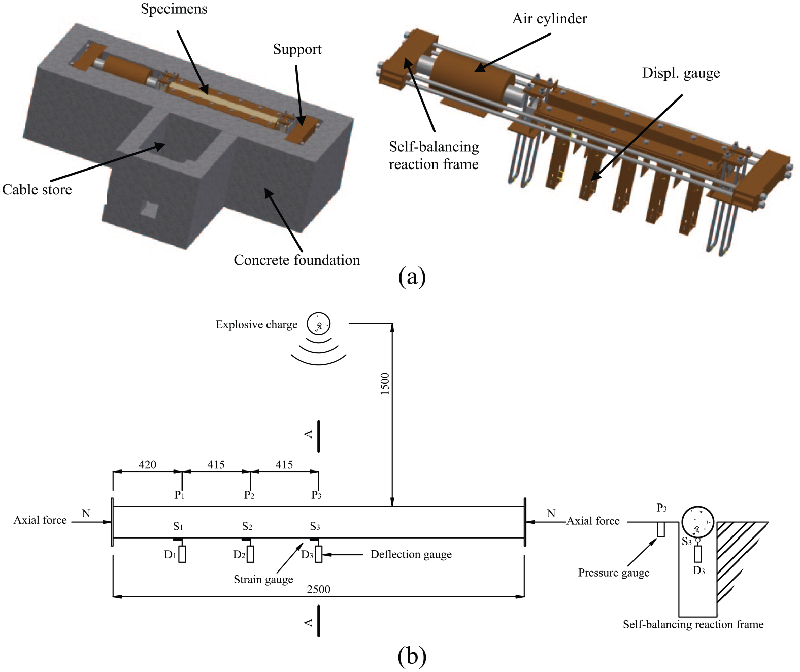
Blast test set-up: (a) blast-resistant test system and (b) recorded arrangement.
Explosive charge is detonated by an electric detonator, while RPC-FST column is installed. Recorded parameters include overpressure of shock wave, deflection of RPC-FST column, and strain of outer steel tube. The test set-up is displayed in Figure 7, where Pi represents the pressure-recorded point, Si represents the strain-recorded point, and Di represents the deflection-recorded point. The fixed boundary condition is achieved by connecting one end plate to the reaction frame using high-strength bolts and another end plate to the piston of air cylinder. In order to eliminate the influences of vibration of RPC-FST column during blast loading, blast load is recorded using a pressure gauge fixed on the concrete foundation, as shown in Figure 7(b). The deflections are recorded by three deflection gauges fixed uniformly on one half of specimens. A constant axial force of 754 kN is applied to the end plate of RPC-FST column by air cylinder, representing the vertical load that column bears in practical engineering and it can be recorded by manometer throughout the blast test.
It is noted that, in order to check reliability of above sensors and ensure good connection between RPC-FST column and self-balancing reaction frame, a preloaded test with explosive charge of 1 kg emulsion explosives is conducted before formal tests.
Test results and discussions
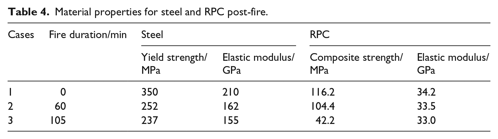
Material properties of steel and RPC post-fire
It is very complex to estimate the residual strength of concrete core after exposure to fire due to that there is an obvious temperature gradient in the cross section of column (Chung et al., 2008; Song et al., 2010), and an approximate approach to calculate the residual strength of RPC core after exposure is presented by the author. Therefore, the average residual strength of RPC core post-fire can be determined by following formula if RPC core is divided into i annuli according to temperature gradient
where
The annulus area of steel tube can take the total cross section of steel tube due to its good thermal conductivity, and the maximum temperature that steel tube having been exposed to is approximately equal to the inner temperature of fire stove (Chung et al., 2008). The maximum temperature that No. i annulus of RPC core can be numerically simulated using ANSYS codes, and the temperature distribution of RPC-FST column section after exposure to fire of 60 and 105 min are displayed in Figure 8, respectively.
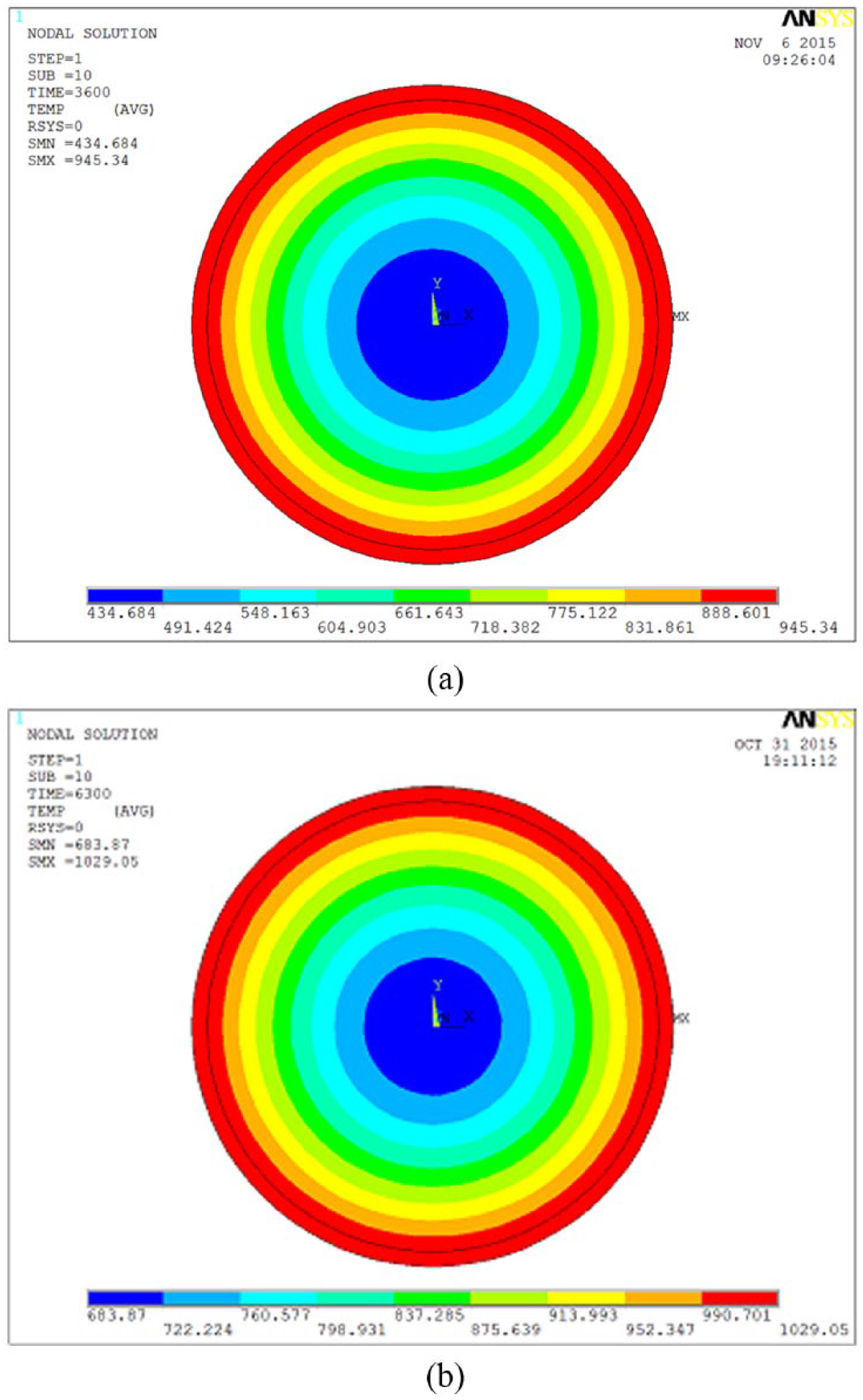
Temperature distribution of RPC-FST column post-fire: (a) t = 60 min and (b) t = 105 min.
It is indicated that the concrete mechanical properties do not recover after having exposed to the maximum temperature Tmax. Therefore, the properties are only dependent on the peak temperature experienced, but not affected by the current temperature during the cooling phase (Yang et al., 2008). Hence, the residual strength No. i annulus of RPC core at post-fire phase can be determined by equation (5) (Song et al., 2010)
where
The residual strength of steel tube after exposure to maximum temperature Tmax can be calculated by the following formula
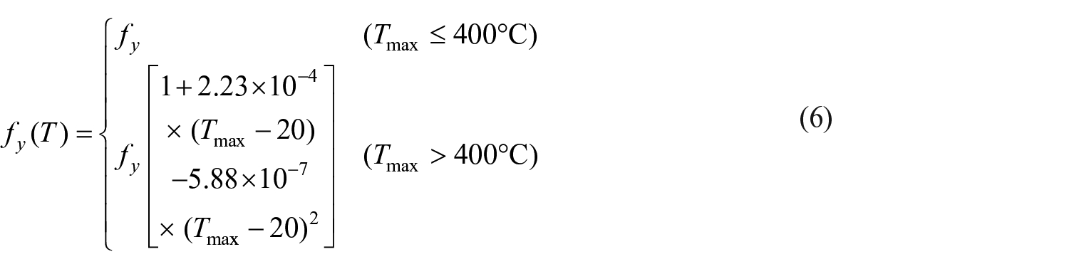
The material properties of steel tube and RPC core after exposure to fire of 60 and 105 min are summarized in Table 4, where the residual modulus of elasticity is determined according to Yang et al. (2008) and Lie et al. (1992). It is indicated that the compressive strength of RPC is sensitive to fire duration, which decreased by 63.7% when fire duration increased from 0 to 105 min.
Material properties for steel and RPC post-fire.
Overpressure of air blast
The explosive charge weight with 17.5 or 35 kg TNT is used to produce air blast, the corresponding scaled stand-off distance is 0.58 and 0.48 m/kg1/3, respectively. The recorded overpressures for different measuring points are summarized in Table 5. It is found that the peak pressure value attenuated rapidly as scaled stand-off distance increased due to the influences of scaled stand-off distance and incident angle. It is worth noting that there are many unexpected factors affecting the recorded data in the testing site. The scaled stand-off distances in this test is less than 0.6 m/kg1/3; thus, the recorded overpressure might be a combination of air blast and product of explosive charge, therefore, the overpressures are larger than that of an ideal explosion. On the other hand, the pressure gauges are fixed on the rigid foundation, so the reflected coefficient might exceed 2. But an approximate way to predict the overpressure including incident angle is to use the ConWep air blast model (Kingery, Bulmash, 1984), which was derived empirically from a large number of well-designed blast experiments. ConWep air blast model has been widely adopted to investigate the structural response under blast load, and it has shown a high level of accuracy with a reasonable computational cost compared with other techniques (Zhang et al., 2015b). The blast load that acts on a set of user-predefined receptor segments (the area that faces the explosive normally), and the magnitude of overpressure P that acts on each segment is calculated by

where pi and pr are the incident pressure and reflected pressure, respectively, and θ is the angle of incidence of the pressure wave.
Overpressure of measuring point.
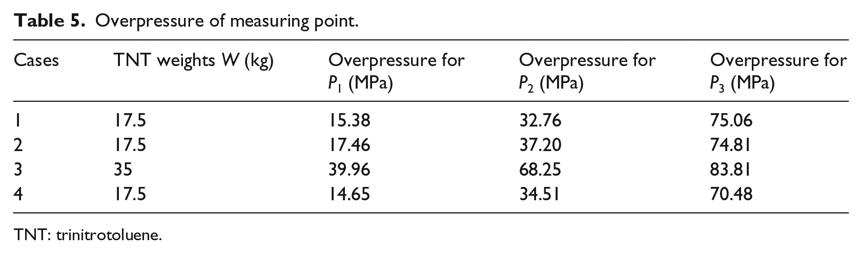
TNT: trinitrotoluene.
The variations of overpressure versus time for case 4 are given Figure 9. It is found that a typical time history of overpressure versus time is derived, but the peak pressure produced by the air blast can be considered as non-uniformly distributed due to that it is in the scope of near-field detonations. It can be seen that the overpressures rise rapidly to the maximum values and attenuated relatively slowly.
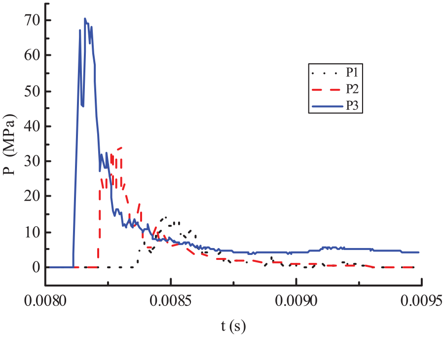
Variations of overpressure versus time (case 4).
Failure modes
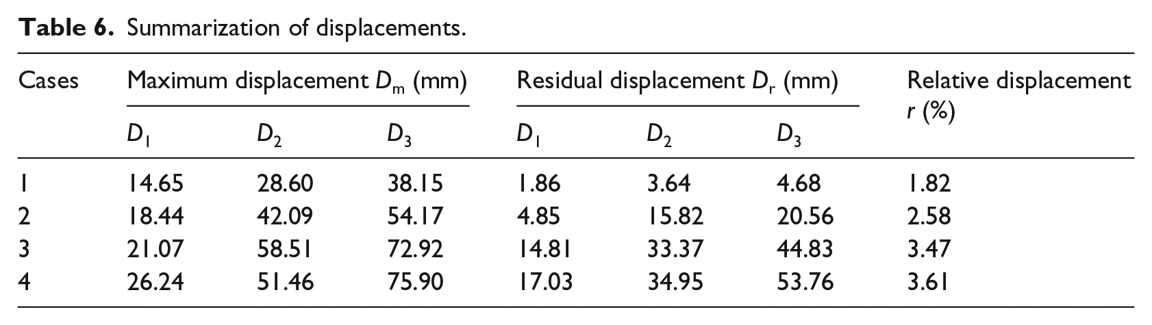
The influences of fire duration and explosive charge weight on dynamic behaviors and failure modes are analyzed in this section. The residual deformations of RPC-FST columns from test case 1 to case 4 are displayed in Figure 10. It is apparent that there is no obvious deformation that can be observed in the RPC-FST column without fire exposure (RPC-FST1). However, severe deformations occur in other columns after exposure to fire; moreover, the deformations tend to be more obvious as either fire duration or explosive charge weight increased. There are no cracks and dilations that can be observed in all RPC-FST columns, and it is also found that there are no plastic hinge that appears in the middle section of columns, which is kindly different from the failure mode of reinforced concrete column. It means that the RPC core can be effectively confined by its outer steel tube, and the excellent blast-resistant capacity and good ductility of RPC-FST are experimentally verified.
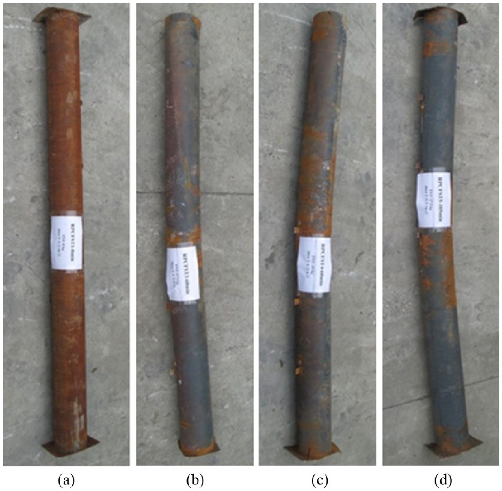
Failure modes of RPC-FST column: (a) RPC-FST1, (b) RPC-FST3, (c) RPC-FST4, and (d) RPC-FST5.
Influences of fire duration
The maximum and residual deflections of RPC-FST columns with different fire durations are shown in Figure 11 (corresponding to case 1, case 2, and case 4 listed in Table 1), where the recorded displacements are linked by straight lines. It is observed that bending deformations occur in all specimens, the maximum displacements of middle section increased greatly as fire durations augmented. The figures of residual deformation show that the residual deflection of RPC-FST column with fire duration of 0 min, as shown in solid line in Figure 10(b), is obviously smaller than that of with fire duration of 65 or 105 min, which means that the deformations change from the elastic range to the plastic range with the increase in fire duration. Because of that the compressive strength of RPC decreased by 10.2% and 63.7%, respectively, compared with column without fire exposure (case 1) according to Table 4; moreover, the yield strength and the modulus of elasticity of steel tube also decreased greatly as fire duration increased. It is important to notice that the plastic deformation tends to be more obvious as fire duration increased from 65 to 105 min. Furthermore, a curve of residual deflection with “V” shape is observed when fire duration is up to 105 min, because that the severe plastic deformation is mainly focused on the mid-span section. As shown in dotted lines in Figure 11(b) that one half of the axis of RPC-FST3 and RPC-FST5 remained almost straight, therefore, bending failure is the main failure type for RPC-FST columns after exposure to fire. The reasons might be that the strengths of steel tube and RPC decreased as fire duration increased; thus, the combined strength at middle section reached its ultimate strength under blast loading. Most of explosive energy is transformed into the kinetic energy. On the other hand, the axial force would also result in bigger mid-span deflection once initial deflection occurs.
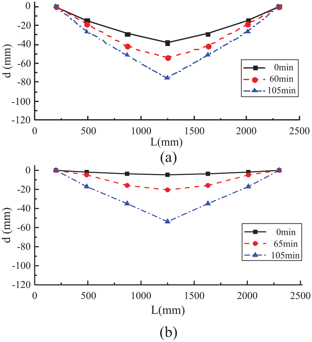
Influences of fire duration on deflections: (a) maximum deflection and (b) residual deflection.
Influences of scaled stand-off distance
The influences of scaled stand-off distance on deflections of RPC-FST columns with fire duration of 60 min (i.e. case 2 and case 3) are given in Figure 12. Explosive charge weights of 17.5 and 35 kg TNT, corresponding to scaled stand-off distances of 0.58 and 0.48 m/kg1/3, are discussed, respectively. A smooth deflection curve is derived for either RPC-FST3 or RPC-FST4, and it is similar to the deflection curve of beam member under static loading. It is observed that there are three plastic inflections in RPC-FST columns: one at the mid-span and two near the fixed ends. The deflection curves seem smoother than that of RPC-FST5, because the smaller scaled distance (case 4) might cause more localized pressure. Typical bending deformations occur in the column with scaled stand-off distance of 0.58 m/kg1/3, but the failure modes tend to be bending-shear type for column with scaled stand-off distance of 0.48 m/kg1/3 due to that two plastic inflections near the fixed ends become more obvious. There are no cracks or obvious plastic hinge that can be observed at the mid-span section, and a smooth curve of residual deflection with “U” shape can be seen, as shown by dotted lines in Figure 12(b). It is important to note that the failure of beam, column, or slab subjected to blast loading can generally be classified into three modes: bending type, bending-shear type, and direct shear type (Qin and Wu, 2003; Xu et al., 2014). That is, a direct failure in member body due to the stress wave, a transverse shear failure near the support sections due to the high shear force, and a flexural failure pertaining to large local and global deformation of the steel tube. If the magnitude of the stress wave is large enough, massive failure may occur in the member body in a very rapid manner. The failure in the second phase is governed by the shear near the support regions, and it greatly depends on the blast impulse. If a member can survive into the third phase, it will exhibit a typical response characteristic, and the failure is governed by large global as well as local deformations (Sun, 2006). RPC-FST has a series of advantages, such as high strength, good ductility, and fire-resistant capacity; thus, it can sustain a large value of shear force near the support and avoid the direct failure.
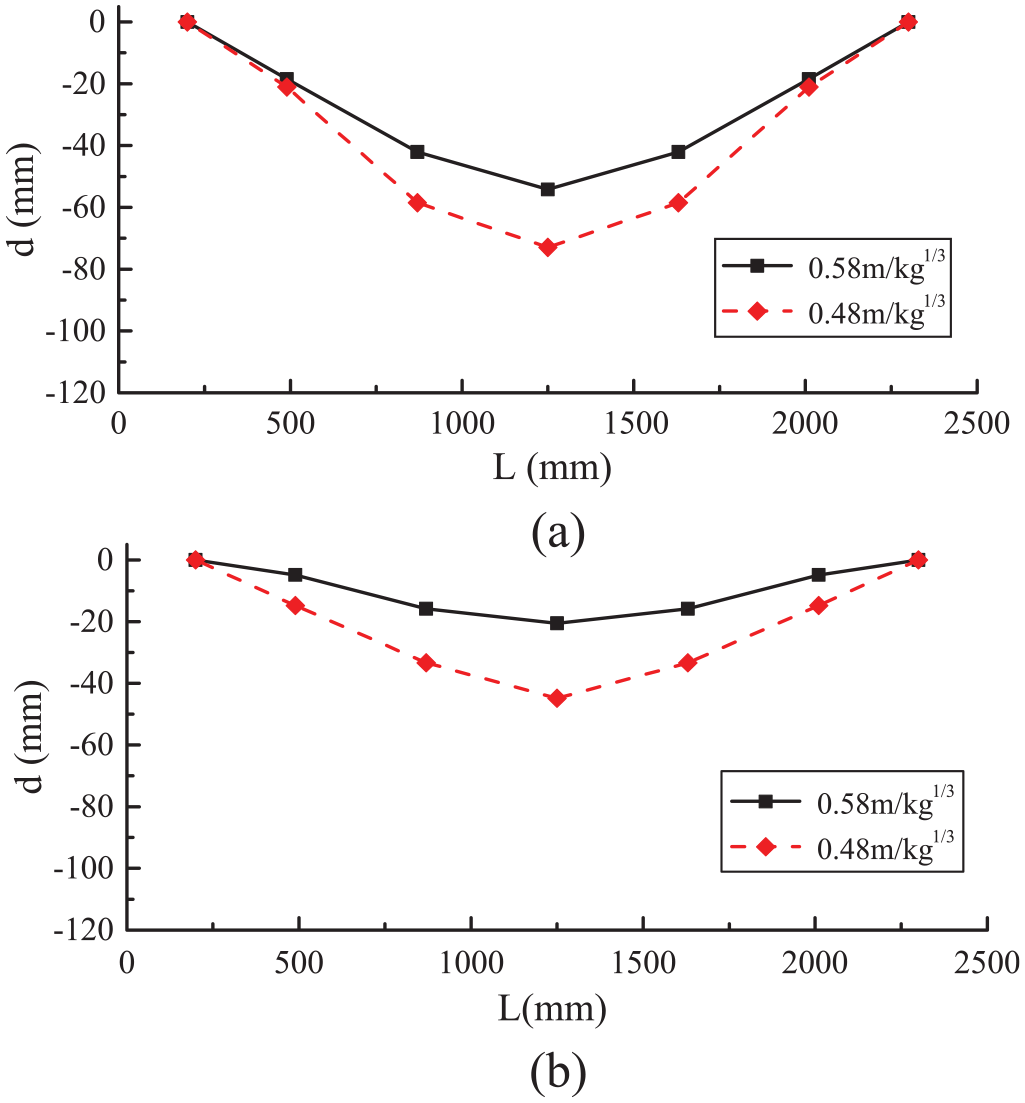
Influences of scaled stand-off distance on deflections: (a) maximum deflection and (b) residual deflection.
Dynamic strains of outer steel tube
Strain is an important parameter to describe the value of plastic deformation, but it is hard to be recorded in blast test, because the strain gauge is usually damaged by shock wave. Most of strains in this test could not be recorded, because the strain gauges are pulled off by the tensile wave reflected on free boundary of the column. The variations of axial strains versus times for RPC-FST1 (case 1) are displayed in Figure 13. It is observed that the maximum strain of measuring point S1 was 2524 µε, and the residual strain is very close to 0 µε. The maximum strain of measuring point S3 is up to 5870 µε, and the residual strain is 920 µε, therefore, the steel tube of mid-span is in the yielding stage and plastic deformations occur.
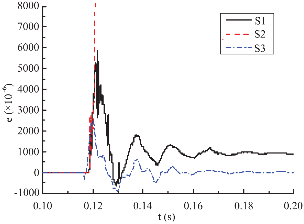
Time histories of strain for RPC-FST1.
Mid-span displacements
The maximum and residual displacements of all measuring points are summarized in Table 6. It can be seen that the maximum and residual displacements of all RPC-FST columns increased as explosive charge weights or fire durations added. A ratio of residual displacement to full length of CFST column r = Dr/L (i.e. relative displacement) was defined by Cai (2007). It was widely used to scale the yielding state of a CFST member, r⩾2% means that the column is in the yielding state and plastic deformation would occur. It can be seen that most of the relative displacements, r, of RPC-FST column are larger than 2% except RPC-FST1; therefore, the RPC-FST columns after exposure to fire are all in the yielding states. With respect to case 2, it is indicated that the residual displacements of D3 of case 3 and case 4 increased by 118.0% and 161.5%, respectively. It means that the residual displacements of RPC-FST columns are more sensitive to fire durations than to explosive charge weights. The displacement obtained from case 4 is much larger, because the curvature is localized at the mid-span section due to the plastic deformation; thus, the column fails with a relatively large deflection. On the other hand, for case 3, the curvature is distributed along the whole column due to bending-shear tendency; hence, the column undergoes a smaller displacement before reaching the ultimate limit state. Time histories of displacement for four RPC-FST columns are displayed in Figure 14.
Summarization of displacements.
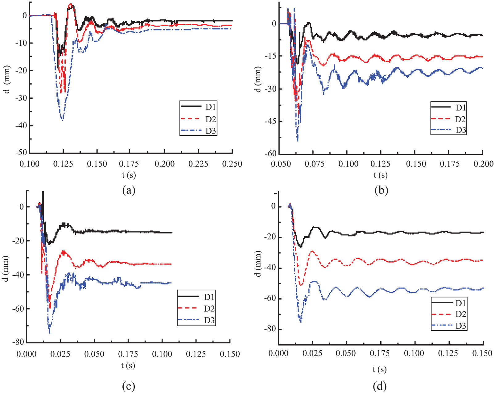
Time histories of displacement: (a) RPC-FST1, (b) RPC-FST3, (c) RPC-FST4, and (d) RPC-FST5.
Conclusion
ISO-834 standard fire exposure tests on RPC-FST columns are performed in this article, and the ANSYS code was used to simulate the temperature gradient of cross section of RPC-FST columns. Then, the weighted average method was employed to approximately estimate the residual strength of RPC core after exposure to fire. Finally, blast tests on four large-scale RPC-FST columns after exposure to fire were carried out, and the influences of explosive charge weight and fire duration on dynamic behaviors and failure types were discussed.
It is indicated that there is an obvious temperature gradient in the cross section of column, and the compressive strength of RPC is sensitive to fire duration, it decreased by 63.7% when fire duration increased from 0 to 105 min. Bending deformations occur in all RPC-FST columns, the maximum and residual displacements ascended as explosive charge weights or fire durations increased. The maximum displacements increased greatly as fire durations rose due to the plastic deformation at its mid-span section. The deformations changed from the elastic range to the plastic range with fire duration increased. It is important to notice that the plastic deformation tends to be more obvious as fire duration increased from 65 to 105 min; furthermore, a curve of residual deflection with “V” shape is observed if fire duration is up to 105 min. Typical bending deformations occur in the specimens with scaled stand-off distance of 0.58 m/kg1/3, but the failure modes tend to be bending-shear types for specimens with scaled stand-off distance of 0.48 m/kg1/3, and a smooth curve of residual deflection with “U” shape can be seen. It is also indicated that the maximum displacements of RPC-FST columns are more sensitive to fire duration than to explosive charge weight.
Footnotes
Declaration of conflicting interests
The author(s) declared no potential conflicts of interest with respect to the research, authorship, and/or publication of this article.
Funding
Funding from the National Natural Science Foundation of China (grant: 51378498, 51578541) and the Natural Science Foundation (grant: BK20141066) of Jiangsu Province.