
Abstract
Aluminium foam is widely known as an energy absorptive material which can be used as a protective cladding on structures to enhance blast resistance of the protected structures. Previous studies show that higher density provides larger energy absorption capacity of aluminium foam, but results in a larger transmitted pressure to the protected structure. To lower the transmitted pressure without sacrificing the maximum energy absorption, graded density foam has been examined in this study. An analytical model is developed in this article to investigate the protective effect of linear density foam on response of a structure under blast loading. The model is able to simulate structural deformation with reasonable accuracy compared with experimental data. The sensitivity of density gradient of foam cladding on reinforced concrete structure is tested in the article.
Introduction
As a protective material, aluminium foam claddings are able to mitigate blast effect on the protected structures by absorbing a significant amount of kinematic energy (Hanssen et al., 2002; Schenker et al., 2005; Wu et al., 2010; Ye and Ma, 2007). The outstanding energy absorption capacity of aluminium foams is contributed by the cellular structure with gas-filled pores which provides a plateau of stress after deformation. The volume proportion determines the density and strength of aluminium foams which directly affect the protective performance. When blast load is applied, the foam cladding will absorb a significant amount of energy and transfer the intensive load into a much lower pressure with a longer duration onto the protected structure. Theoretically, the plateau stress of the foam is equal to the pressure transmitted from the foam onto the target structure (Li and Meng, 2002). Since the plateau stress exhibits a power law function with density (Ashby et al., 2000; Hanssen et al., 2002), the density of the aluminium foam is one of the key properties when designing protective cladding.
As demonstrated by the natural density-graded bone and wood, grading the density of foam cladding may be an effective method to increase the protective effectiveness and efficiency. According to several numerical studies in regard to double, triple and quadruple layers of aluminium foams (Chang et al., 2013; Li et al., 2011; Ma and Ye, 2007), it appeared that under dynamic loading, density-graded foams with decreasing density from loaded end to protected end outperform homogeneous foams with the same average density. When dynamic loading is applied, the low-density layer at the bottom, which is in direct contact with the protected structure, will transmit a relatively lower pressure to the structure compared with homogeneous foam with the same average density. As a result, the deformation of the protected structure against blast loading can be smaller.
Techniques have been developed to manufacture continuously graded density aluminium foams (Brothers and Dunand, 2006; Hassani et al., 2012; He et al., 2014; Higuchi et al., 2012), which allows experiments to be undertaken. Similar to the findings from the aforementioned numerical studies, experimental results showed that the density gradient increases the slope of the plateau stress range of the foam (Beals and Thompson, 1997; Brothers and Dunand, 2008; Xia et al., 2016). This means that the transmitted pressure onto the protected structure will depend on how the graded density foam deforms, rather than a constant plateau stress of homogeneous foam. For example, if the blast load is relatively small and only the lower density part of the foam is compacted, the transmitted pressure will be the strength of the lower density foam, which is smaller than the plateau stress of the homogeneous foam with the same average density. However, when the blast load is high enough to fully compact the entire graded density foam, the transmitted pressure will depend on the foam density which is densified finally. Researchers have found that graded density foam will always deform from the loaded end gradually through the thickness regardless the density distribution if the loading velocity is large enough (Li et al., 2011, 2012; Shen et al., 2013). Hence, theoretically, decreasing the foam density from loaded end to protected end will improve the protective effectiveness of foam cladding. Furthermore, a series of blast tests conducted by Xia et al. (2016) also indicates that the foam with decreasing density from loaded end protects the reinforced concrete (RC) slab better than uniform density foam.
Analytical model is a convenient and economical method in investigating the protective effect of aluminium foam against blast loading. The one-dimensional shock wave theory has been verified numerically and experimentally in the analysis of aluminium foam under blast loading (Hanssen et al., 2002; Li and Meng, 2002; Reid and Peng, 1997; Xia et al., 2014a). Based on the shock wave theory and single degree of freedom theory, loading-cladding-structure models have been developed to predict the response of structural members with homogeneous foam cladding (Xia et al., 2014a; Ye and Ma, 2007). Recently, a theoretical model of continuous graded density foam under blast loading was established by Zhou et al. (2015). In this model, the foam density was designed as a decreasing exponential function and the study concludes that the density gradient makes foam densify slower (Zhou et al., 2015). However, no foam–structure interaction was considered in this theoretical model.
In the current research, an analytical model, which contains a cover plate, a linear density foam cladding and a protected structure, is developed to investigate the protective effect of linear density foam on the structure under blast loading. The proposed analytical model is verified by blast experimental results conducted by Xia et al. (2016). Moreover, parametric studies are carried out to test influence of different parameters of linear density foam on reducing the peak deflection of protected RC slab. In addition, two different slabs are used in the parametric study to test the protective effects of linear density foams on different structures.
Derivation of analytical model
The blast pressure considered in the model is simplified as a triangular pulse and uniformly acts on the cover plate of the foam cladding, which is expressed by equation (1)

where
For linear density foam, the density can be calculated with the distance

where
The analytical model in this article is developed based on shock wave theory (Reid and Peng, 1997) which assumes that the foam deforms gradually from the loaded end through the cross-sectional direction under blast load as illustrated in Figure 1. The foam is idealised as a rigid, perfectly plastic locking (RPPL) material with a plateau stress


where

where

Graded density foam–protected RC model under blast loading.
The mass of the densified part of the foam cladding can be calculated by the product of densified foam density and densified foam volume

where

When considering the density of the originally undeformed foam

Equating equations (6) and (8), the displacement of the cover plate can be ascertained in a function of the shock front location

With initial conditions


The system of the densified foam with cover plate in Figure 1 is considered as a single degree of freedom system where damping is ignored. The dynamic equation of motion is written as

where

The motion equation of the system of the undeformed foam with protected structure (as shown in Figure 1) can be expressed as

where

From the simultaneous nonlinear differential equations (13) and (15), the deflection of the protected structure
The current analytical model is only applicable when satisfying the Shock Wave Theory. Researchers have proved that sufficient impact velocity will make the graded density foam densify progressively from the loaded end (denser end) while keeping the other part of foam undeformed (Li et al., 2011, 2012; Shen et al., 2013). Therefore, an important assumption of the analytical model in the present article is that the blast load is large enough to deform the foam from the loaded end progressively toward the structure.
When the foam cladding is totally densified along the thickness, the densified foam will move in unison with the protected structure. Therefore, the covered foam and the protected structure can now be seen as a single degree of freedom system

Equations (13), (15) and (16) form an analytical model which can theoretically calculate the deformations of linear density foam cladding and protected structure. The running cost of this model is low and suitable for huge amount of parametric studies on protective effect of linear density foams. This proposed analytical model is applicable for different types of foams and different target structures with different resistance functions
Verification of analytical model
The analytical model is verified by the full-scale blast test conducted by Xia et al. (2016). In the blast test, the blast loads and the protected RC slabs in all events are the same. The 8-kg TNT (trinitrotoluene) charges used in the test are cylindrical with a diameter of 225 mm and a height of 120 mm. All charges were placed vertically on the top of the RC slabs as shown in Figure 2. The standoff distance from the charge to the centre of the RC slab is 1.5 m. All the protected RC slabs are 2000 mm long, 800 mm wide and 120 mm thick and more details can be referred in Xia et al. (2016). Every aluminium foam tested in the experiment was covered by a 1.13-mm-thick steel cover plate and was glued on the RC slab by epoxy. Three major elements are required by the analytical model to verify its predictions: (1) pressure–time history of the blast load, (2) resistance–deflection function of the protected RC slab and (3) density distribution of the aluminium foams.
Setup of the blast test.
Simulation of the blast load
Due to the fact that the pressure–time history during the blast event (Xia et al., 2016) was not successfully recorded, the pressure–time history applied on the analytical model is therefore calculated by using LS-DYNA.
In LS-DYNA, the Arbitrary Lagrangian–Eulerian (ALE) Method is used to accurately model the wave–structure interaction. It is previously mentioned that a cylindrical explosive was used during the experiment; however, the current built-in ConWep functions in LS-DYNA are only able to account for spherical or hemispherical explosive. Therefore, the TNT explosive and the surrounding air domain are both explicitly modelled in the subsequent numerical simulation.
As shown in Figure 3, hexahedral elements are used for all numerical components to achieve the best computational stability and accuracy. The air mesh extends approximately 10 cm beyond the slab’s edges and bottom. To maximise the efficiency, an eighth-symmetry model is used by imposing appropriate boundary conditions to the nodes lying on the x–y, y–z and x–z planes which intersect at the explosive centre while nonreflecting boundary conditions are forced on the remaining exterior surfaces of the air domain. To output the pressure–time history, a pressure transducer is placed at the centre of the slab.
ALE model employed for determination of blast pressure.
The constitutive model *MAT_HIGH_EXPLOSIVE_BURN is used to model TNT explosive and the equation of state is *EOS_JWL. Standard input parameters (Kingery and Bulmash, 1984) for the constitutive model and equation of state are used and the detonation point is assumed at the centroid of the explosive.
The ambient air domain is modelled by *MAT_NULL with the density of air being the sole material input. The equation of state is *EOS_LINEAR_POLYNOMIAL.
In the current study, the only purpose of the numerical simulation is to obtain the reflected pressure–time history for the proposed analytical model, the response/behaviour of the structure itself in LS-DYNA is not of interest. Therefore, the slab is modelled as a rigid body with *MAT_RIGID to minimise the computational effort.
The simulated pressure–time history on the central point of the slab is presented in Figure 4. To apply to the analytical model, the pressure–time history is idealised into a triangular load as shown by the dashed line in Figure 4. The idealised pressure has a peak reflected pressure of 18 MPa to match the simulated peak pressure. A duration of 0.6 ms is adopted to match the impulse neglecting the low-pressure tail. In the idealisation, the extensive low-pressure range after 0.001 s is ignored so that the idealised impulse is slightly smaller than the simulated pressure. The idealised pressure will be uniformly applied on the slab in the analytical model whereas the actual pressure will experience clearing, therefore, the influence of the neglecting the low-pressure tail will compensate the overestimated pressure on the sides of the slab.
Pressure–time history in the blast test.
Resistance function of the RC slab
According to Xia et al. (2016), the bilinear resistance–deflection diagram (Figure 5) of the RC slabs used in the blast test is calculated by


where
Resistance–deflection diagram of RC slabs in the blast test.
Aluminium foams in the blast test
Three aluminium foam claddings in the blast test (Xia et al., 2016) are referred in the current study: one uniform density foam UD300 and two linear density foams LD300 and LD400. Due to the manufacturing process, the density cannot be perfectly controlled as per the designed value. For a clear comparison, the approximate density distribution introduced in Xia et al. (2016) will be used in the analytical model as listed in Table 1. Figure 6 shows the configurations of aluminium foams before and after explosives in the blast tests.
Density distributions of aluminium foams.

Configurations of foams in blast test.
Result comparisons
Four events of the blast test (Xia et al., 2016) are simulated by the analytical model. Table 2 summarises the results from the experiment and the analytical model.
Experimental and simulated results of peak deflection.
The first event in the blast test is an unprotected RC slab under the explosive loading. The deflection–time history is calculated by a basic single degree of freedom model with the resistance function shown in Figure 5. The comparison with experimental result in Figure 7 shows a good agreement until the peak deflection is reached. This indicates that the idealised pressure–time history is reasonable. After the peak deflection, the predicted curve keeps at the high level because damping effect is not considered in the model.

Deflection–time diagrams of the unprotected RC slab.
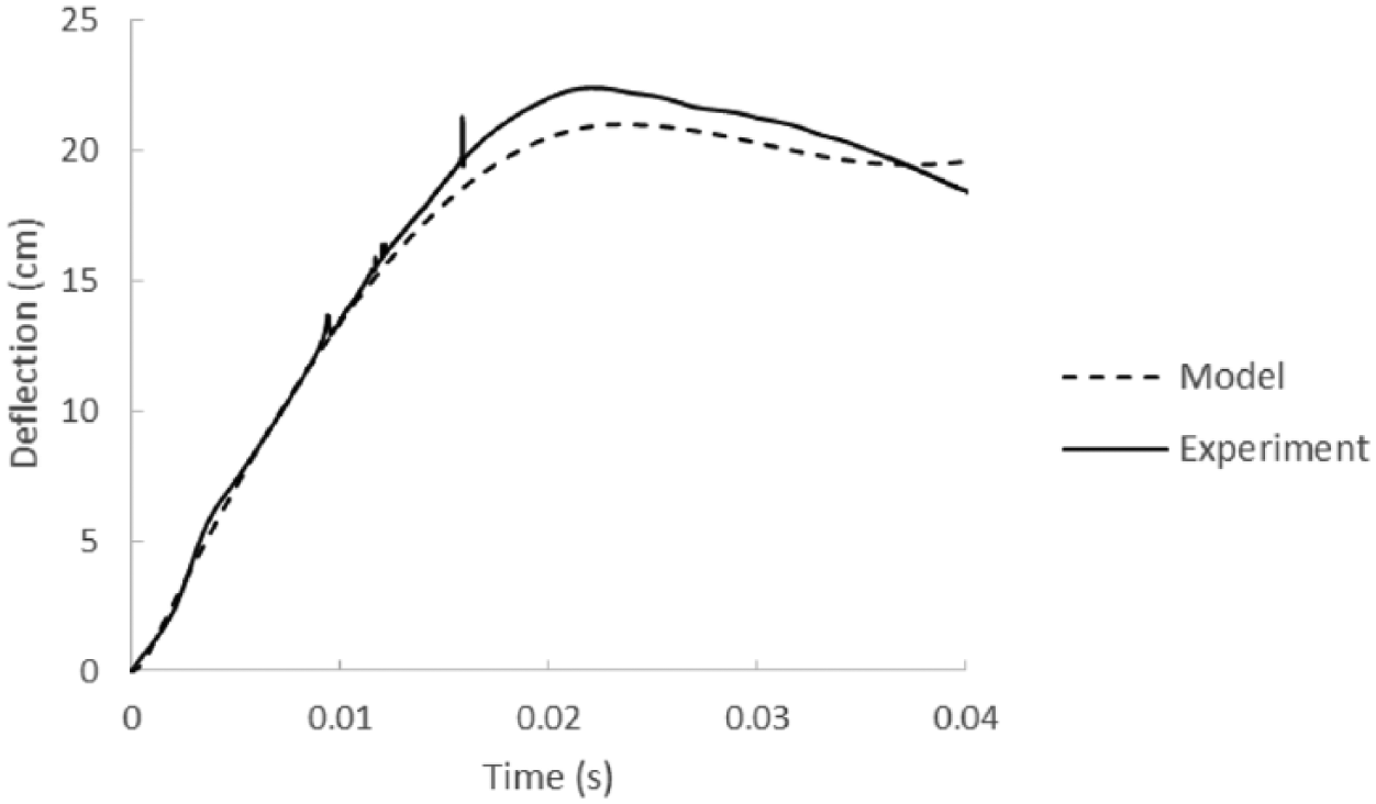
The analytical model introduced in this article is verified by comparing the deflection–time diagrams of RC slabs with experimental results where foams UD300, LD300 and LD400 were employed, respectively, in the tests (Xia et al., 2016). The uniform density foam UD300 is modelled by setting the initial density equal to the final density of the foam. The model yields an error of 8.3% on peak deflection (Figure 8) which is acceptable in blast analysis. For linear density foams LD300 and LD400, the predicted results are shown in Figures 9 and 10. The simulated peak deflections and periods of the protected slabs are matched; however, the simulated deflections after peaks are not reliable due to ignoring the damping effect. Therefore, the current model is only applicable in the calculations of peak deflection. It was observed that the linear density foam did not show any advantage in the experiment (Xia et al., 2016). This is because the blast load was too intensive and caused all of the RC slabs to fail with significant deformations, so that the actual foam effectiveness is hard to display. Therefore, in the next section, a lower blast load is applied to this verified model to investigate the protective improvement of linear density foam.
Deflection–time diagrams of the UD300-protected RC slab.
Deflection–time diagrams of the LD300-protected RC slab.
Deflection–time diagrams of the LD400-protected RC slab.
Parametric studies
Parametric studies are carried out to investigate the influence of different parameters on the protective effect of linear density foams. A blast load of a peak pressure of 12 MPa and duration of 0.3 ms is applied to all scenarios hereafter. RC slabs used in this section are the same as the ones used during the blast experiment (Xia et al., 2016), and all foams are 80 mm thick unless specified.
Influence of density gradient with the same average density
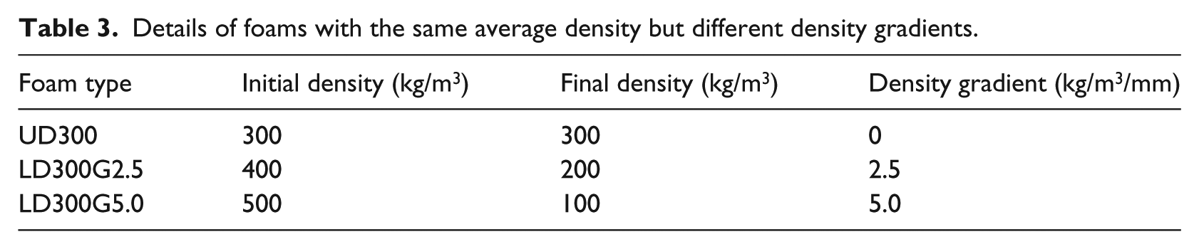
Three foams with same average density of 300 kg/m3, but different density gradients (0, 2.5 and 5.0 kg/m3/mm, respectively) are tested by using the proposed analytical model. The details of the foams are listed in Table 3. As shown in Figures 11 and 12, the homogeneous foam reduces the peak deflection of RC slab by 59% while the linear density foam LD300G2.5 mitigates a further 11.7% on the peak deflection. With an increase of density gradient, linear density foam LD300G5.0 provides an even better protection with a 75% reduction on the peak deflection. The results indicate that the improvement on the protective effect of using density-graded foams is evident, especially when the blast load is large enough to compact the foam from loading end.
Details of foams with the same average density but different density gradients.
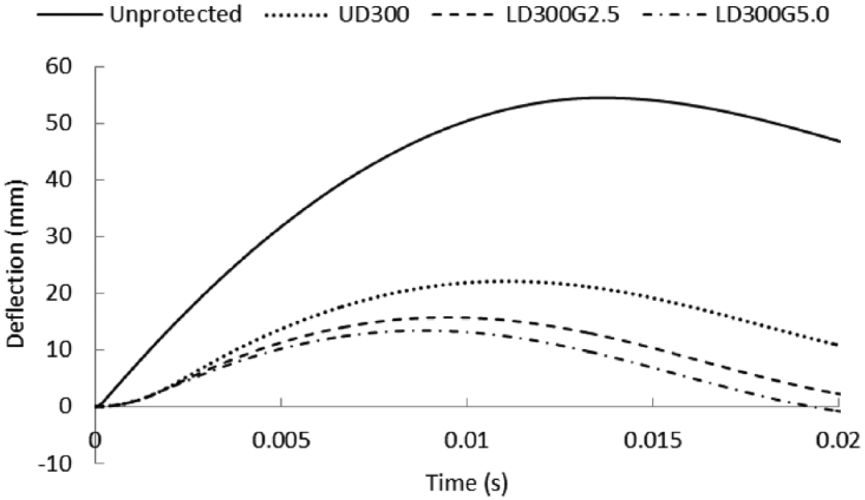
Deflection–time diagrams of RC slabs protected by foams with the same average density but different density gradients.
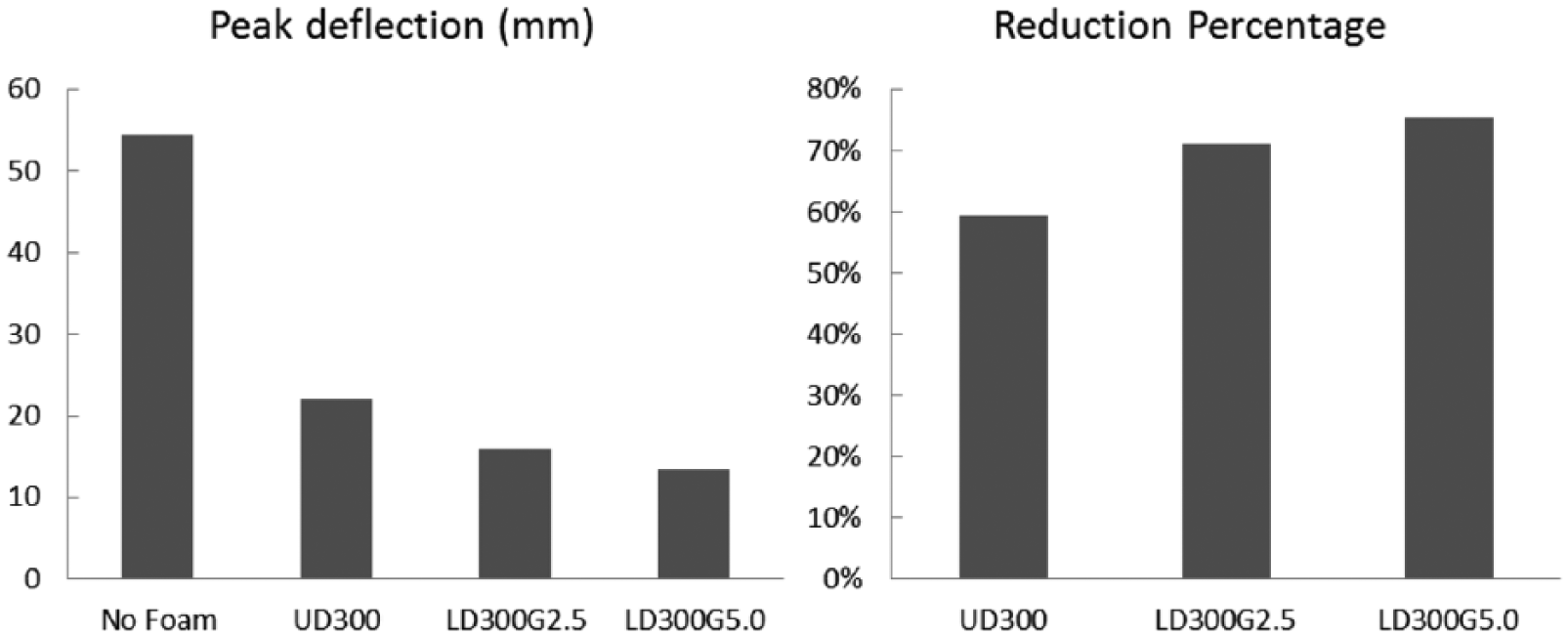
Peak deflections of RC slabs protected by foams with different density gradients and responding percentages of reduction.
Influence of density gradient with the same final density
Once the final-layer density of the foam (the end that is in direct contact with the protected structure) is kept constant, raising the density gradient increases the average density of the foam and therefore, the energy absorption capacity of the foam can be enhanced.
Four foams with the same final-layer density but different density gradients are studied as shown in Table 4. The equal final-layer density means the transmitted pressures on the structure will be the same when the foams are fully densified. This is because theoretically, the transmitted pressure is equal to the plateau stress of the foam that is in direct contact with the protected structure. However, for a given blast load, the densification status of different foams can be different so that the actual transmitted pressures on the protected structure can be different. Figure 13 shows the deflection–time diagrams of the RC slabs protected by the foams with the same final-layer density but different density gradients as introduced in Table 4. Those results indicate that increasing the density gradient from 2.5 to 3.75 kg/m3/mm improves the mitigation effect. However, the further growth of density gradient from 2.5 to 5.0 kg/m3/mm amplifies the peak deflection of the protected RC slab. This is because the FD200G5.0 foam has a larger average density so that it deforms less compared to other types of foam under the same given blast load. Based on the results, it can be concluded that when the final-layer density is constant, the effect of increasing density gradient of the linear density foam is dependent on the intensity of the blast load which determines the extent of the foam deformation.
Details of foams with the same final density but different density gradients.

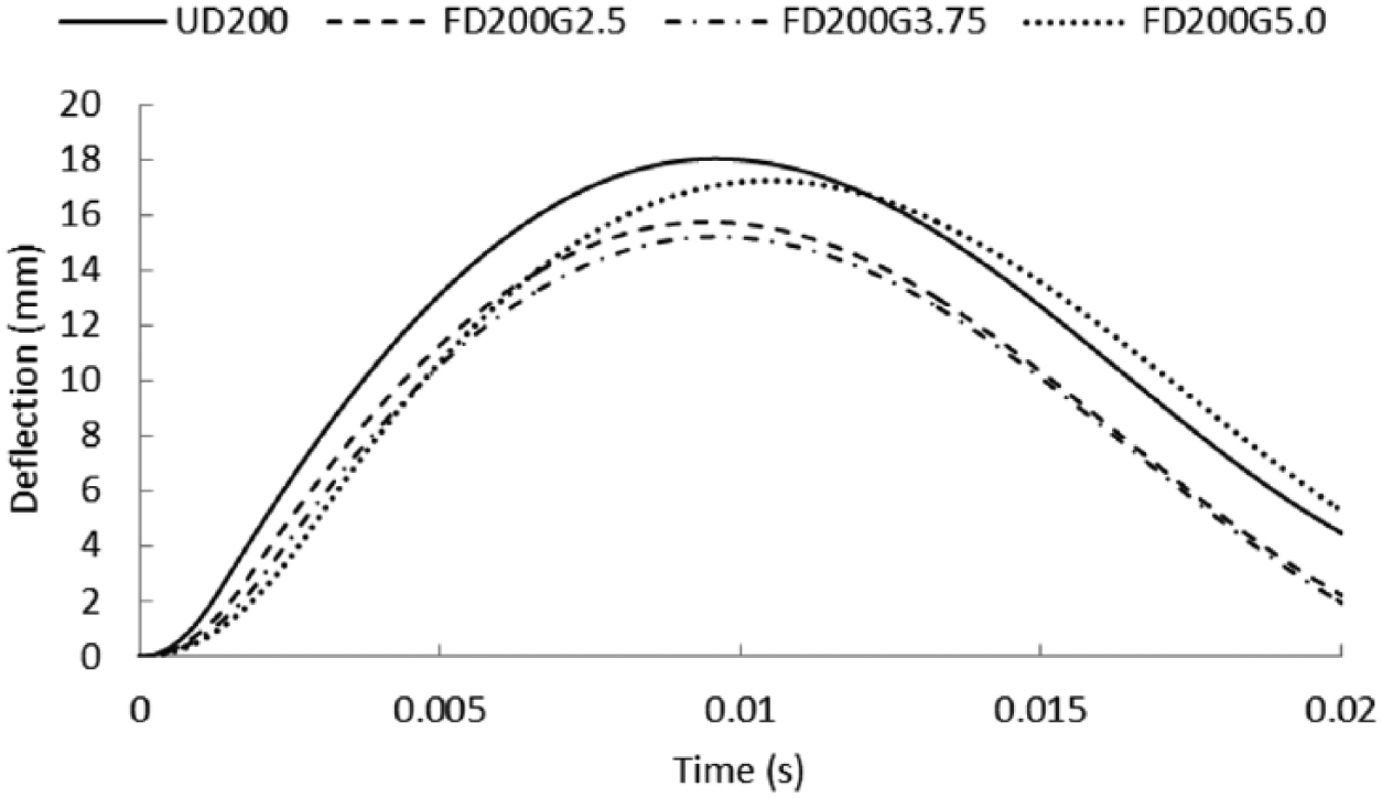
Deflection–time diagrams of RC slabs protected by foams with the same final density but different density gradients.
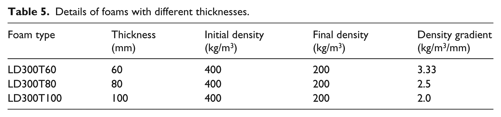
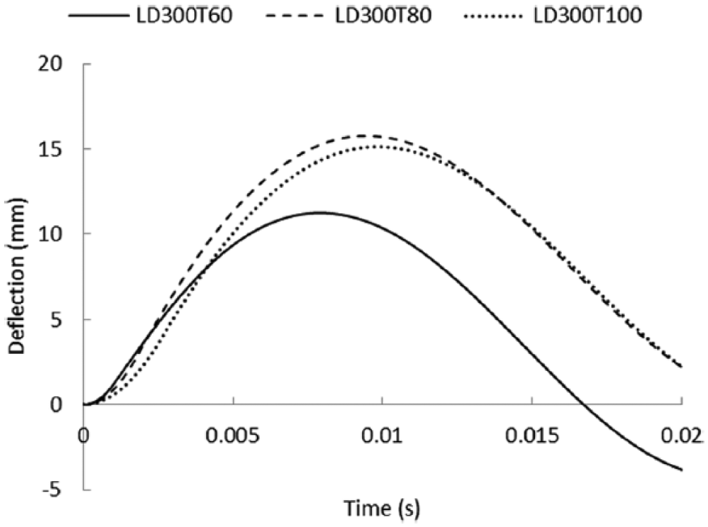
Influence of thickness with the same density distribution
The effect of foam thickness is examined by using three foams of the same density arrangement as summarised in Table 5. Since the three foams have the same initial- and final-layer densities but different thicknesses, the thicker foam therefore has a lower density gradient. From Figure 14, it can be seen that the thinnest foam LD300T60 mitigates the peak deflection of the RC slab most effectively. The other two thicker foams LD300T80 and LD300T100 result similar peak deflections, which indicates that they were not fully densified under the given blast load. Therefore, the thinner foam LD300T60 is more effective and more efficient in this case since it densifies more and transmits a relatively lower pressure to the protected RC slab.
Details of foams with different thicknesses.
Deflection–time diagrams of RC slabs protected by foams with the same density gradient, but different thicknesses.
Influence of average density with the same density gradient
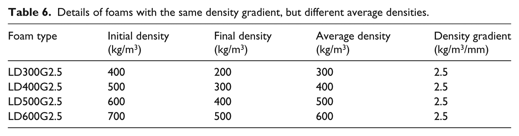
The influence of average density of linear density foams is investigated on two different RC slabs. Slab I is the RC slab used during the blast experiment (Xia et al., 2016) and Slab II has a thickness of 200 mm which is 80 mm thicker than Slab I. All other configurations are exactly the same. The resistance–deflection curves of both slabs are plotted in Figure 15, which are used in the following parametric studies. Table 6 lists the details of foams with different average densities, and the protective effects of these foams on two types of slabs are shown in Figure 16. For a constant density gradient of 2.5 kg/m3/mm, increasing the foam density from 300 kg/m3 to 400 kg/m3 and 500 kg/m3 increases the peak deflection of the Slab I under the given blast load. This is because the foams LD400G2.5 and LD500G2.5 are too strong and the transmitted pressures are too large for Slab I. On the contrary, for the stronger structure Slab II, increasing foam density up to 500 kg/m3 can actually improve the mitigation effect as Slab II is capable of withstanding higher transmitted load. Further increasing the foam density to LG600G2.5 leads to an opposite effect since the transmitted load of LG600G2.5 exceeds the blast resistance of Slab II. These outcomes agreed with the findings from the previous studies on homogeneous foams (Xia et al., 2014a, 2014b), which suggested that foams acted differently on different RC slabs and the foam density should be chosen based on the resistance of the slab to achieve the optimal protection. Within the trials in this study, LG300G2.5 is closer to the optimal protection for Slab I while LG500G2.5 is the closest foam to the optimal design for Slab II. Therefore, the average density of linear density foam is an important parameter to find the optimal design for RC slab.
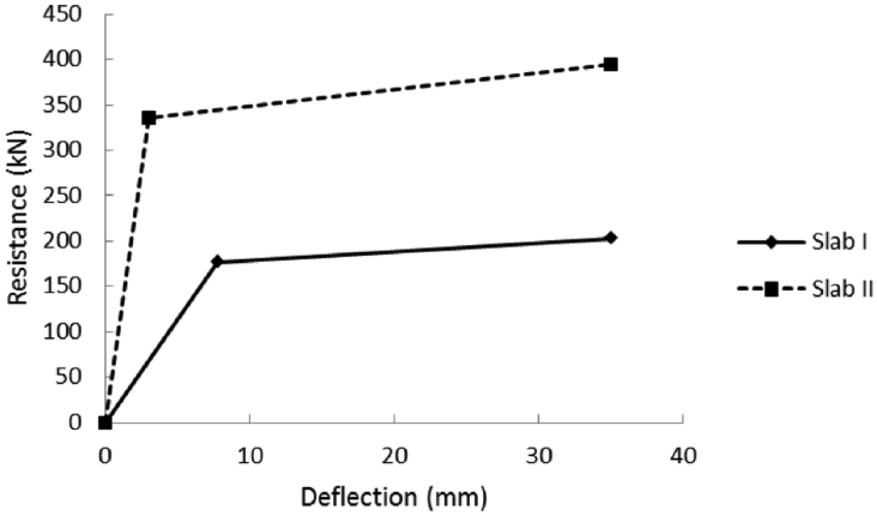
Resistance–deflection diagrams of Slab I and Slab II.
Details of foams with the same density gradient, but different average densities.
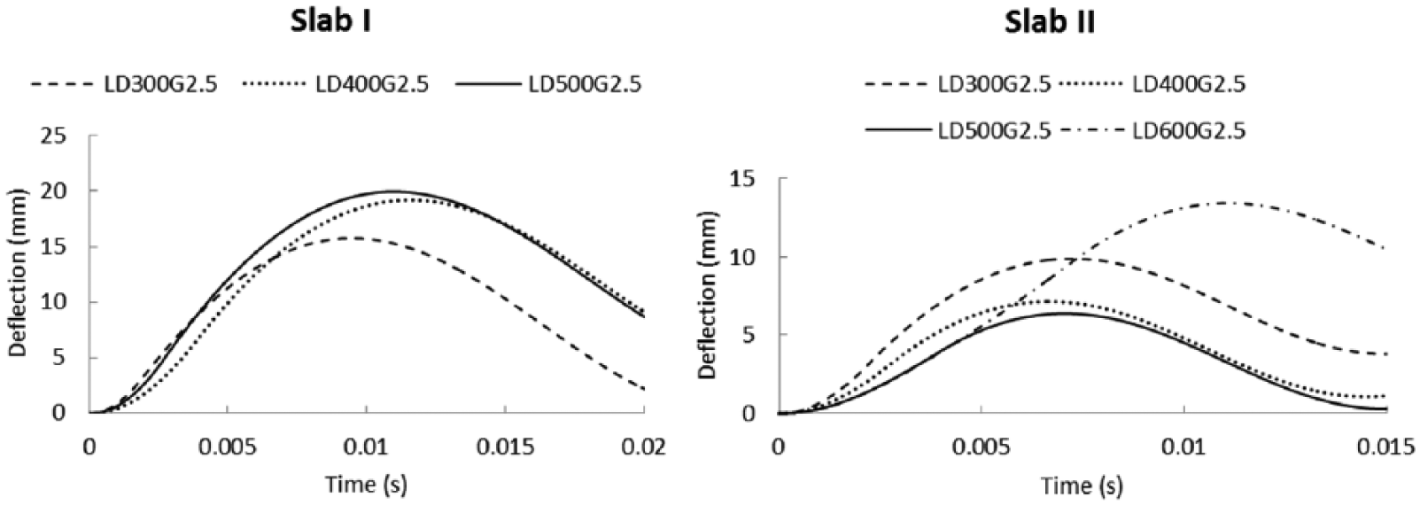
Deflection–time diagrams of Slab I and Slab II protected by foams with the same density gradient, but different average densities.
Comparison of using foam cladding and thickening the slab
Figure 17 shows the comparison of the protective effects of using foam cladding and thickening the RC slab. The solid line is the deflection–time curve of the unprotected Slab II, and the dashed line presents the deflection–time curve of a Slab I protected by a 80-mm foam of LD300G2.5, which has the same total thickness as Slab II. It can be seen that Slab I with foam cladding outperforms the thicker Slab II without foam cladding under the same blast load. Thus, in this case, using foam cladding provides a better blast load bearing protection than simply thickening the slab. This finding is consistent with the study on homogeneous foam in Xia et al. (2014b). It should be noticed that using a foam cladding is not always more effective than thickening the slab. Based on the result from Xia et al. (2014b), when the peak blast pressure is lower than a certain value, the extra slab thickness can perform better. Therefore, the proper foam should be designed based on the expected blast load.
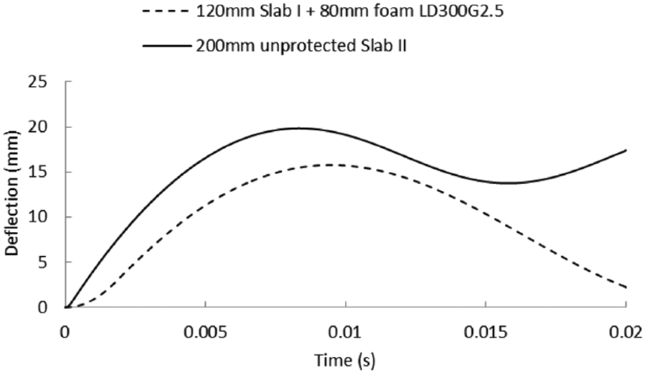
Deflection–time diagrams of foam-protected Slab I and unprotected Slab II.
Conclusion
An analytical model is developed to predict the protective effect of linear density foam on RC slabs under blast loading. The model is verified against some experimental results and yields acceptable accuracy. A range of parametric studies that describe the sensitivities of different parameters of linear density foam are also carried out. The result suggests an improved protective ability of linear density foam over uniform density foam which means linear density foam is capable of mitigating the response of the RC structural member more effectively under stronger explosions:
For a given average density, the increase of density gradient further improves the performance on mitigating the peak deflection of the protected RC slab.
When the final-layer density (protecting end) of the linear density foam is given, larger density gradient provides better energy absorption ability. However, for a given blast load and RC slab, enlarging the density gradient can increase the average density, which can reduce the protective effect on the slab.
The effect of average density of linear density foam on RC slab is similar to that of homogeneous foam: denser foam can protect stronger RC slab better and vice versa.
Using a linear foam cladding on a thinner slab may outperform a thicker slab of the same total thickness in some circumstances.
The findings from this article are valuable for future studies on optimisation of linear density foam design for RC slabs under blast loading.
Footnotes
Declaration of conflicting interests
The author(s) declared no potential conflicts of interest with respect to the research, authorship and/or publication of this article.
Funding
The author(s) disclosed receipt of the following financial support for the research, authorship, and/or publication of this article: The research presented in this article supported by the ARC Discovery Grant DP160104661 is gratefully acknowledged.