



Abstract
The dynamic oblique crushing of circular thin-walled tubes with the presence of non-propagating crack was investigated numerically. The material considered was strain rate sensitive with crack located at the distal end of the tube. Major crashworthiness parameters were obtained and the analysis of the structural response for idealized and finite element crushed thin-walled tubes was also carried out. The study shows that crack initiation on energy absorbing tubes increase their crushing force efficiency under oblique impact, decrease their crushing force efficiency under axial impact and reduce their crashworthiness performance such as the energy absorption capacity and specific energy absorption under axial and oblique impact. Results of the crashworthiness parameters, deformation modes, damage morphology, stress–strain relations, absorption energy characteristics and crushing force-displacement history were obtained. Furthermore, the numerical study reveals both the desirable and undesirable consequence of crack on the overall crashworthiness performance of energy absorbing circular thin-walled tubes.
Keywords
Introduction
The protection of passengers and cargoes during high impact is of utmost importance. Thin-walled tubes are designed for such crashworthiness purpose to reduce the high incidence of injuries, damage and fatalities that could result from such collision. During the deformation of these tubes, structural failure could occur. A major cause of such failure is the presence of crack or discontinuity. The effect of this failure is the reduction in the overall crashworthiness performance of such energy absorbing tubes. Crack initiation on the tube affects the deformation mode and the efficiency of the tube to optimally absorb energy. Moreover, the type of material used as energy absorbers can contribute to the efficiency and energy absorption capacity of the thin-walled structure. Materials that are brittle-like may fracture in a catastrophic way as they reach their maximum tensile strength. These materials could dissipate energy through some fracture mechanisms such as delamination, fibre breakage and matrix cracking (Mamalis et al., 1997). Many composites materials used for energy absorbers are in this category. However, ductile-like materials such as mild steel and aluminium alloy used in crashworthiness application first undergo some form of yielding and the dissipation of energy is through progressive plastic deformation. Despite the advantage of these ductile-like materials, the composite materials have higher specific energy absorption (SEA) than their metallic counterpart (Ramakrishna and Hamada, 1998).
Recent advances in the design of energy absorbing thin-walled tubes show that circular tubes are most efficient. Reid (1993) showed that for a circular thin-walled tube, more than one-half of its length undergo plastic deformation. Also, the type of loading can affect the energy absorption capacity of thin-walled tubes. Oblique impact loading reduces the energy absorption capability of the tube than axial impact loading. This is because during oblique loading condition, the tube is susceptible to bending and the consequence is that not all the tube lengths contribute to plastic deformation. However, under oblique loading, the energy absorption can be improved by filling the tube with foams (Hussein et al., 2017; Li et al., 2015a). A number of researches have been made on the energy absorption of thin-walled tubes under axial impact (e.g. Costas et al., 2016; Hao et al., 2017; Qiang et al., 2017), oblique impact (e.g. Gao et al., 2016; Li et al., 2015b) and a combination of axial and oblique impact loading conditions (Fang et al., 2015b; Pirmohammad and Marzdashti, 2016; Tarlochan et al., 2013). Moreover, the velocity of impact can also affect the deformation time. Two forms of impact speed have been adopted in the crushing behaviour of thin-walled tubes by contemporary researchers. They include the quasi-static and the dynamic forms of impacts (Fan et al., 2013; Fang et al., 2015a; Xu et al., 2014). During the quasi-static or low velocity impact, regular and deformation pattern were observed (Altin et al., 2017; Han et al., 2007). However, most crash scenarios are due to dynamic impact. In this case, the deformation of the tube is erratic and unstable which can be observed from the crushing force-displacement history curve (Al Galib and Limam, 2004; Duarte et al., 2014; Isaac and Oluwole, 2016). The finite element integration schemes that have been used to analyse these two forms of impacts are the implicit and explicit time integration schemes (Kazanci and Bathe, 2012; Noels et al., 2004). The explicit integration scheme has gained popularity than their implicit counterpart because it requires lesser time step for the crushed tubes to completely deform.
Crushing response of energy absorbing tubes has been performed analytically (Enakoutsa, 2014; Hao et al., 2017), numerically (Isaac and Oluwole, 2015; Wu et al., 2017) and experimentally (Eyvazian et al., 2014; Mirzaei et al., 2012). During experimental investigations, a number of crushed tubes develop cracks at their distal end. Severe stress concentration and insufficient time for microscopic movement to take place could lead to crack. Depending on the type of the tube material used, the fracture could be brittle-cracking or ductile-cracking. Very few authors have investigated the crashworthiness performance and damaging effect of cracks on these thin-walled tubes. Crack initiation on the tube predisposes it to a very high plastic behaviour and prolongs the deformation process. Some authors, such as Zavattieri (2006), Zheng (2005), Falzon et al. (2015) and Yang et al. (2015), respectively, modelled crack propagation with a cohesive model for shell element, predicted the formation of crack by the use of s-rails, predicted the impact of damage due to compression in composite and performed fracture analysis of cracks growing from surface to fully through-wall crack in tubular members. Javidruzi et al. (2004) performed finite element study of the behaviour of cracked cylinder shell. In their results, the crack size, crack orientation and loading parameters affect the stability and behaviour of thin-walled cylinder subjected to compressive and tensile loading conditions. Gu et al. (2012) performed a theoretical and finite element analysis of the fracture possibility of squared thin-walled tubes under axial crushing. They found out fracture was more likely to occur with increased tube thickness and the peak value of strains in the tube decreased with wall thickness and circumference. A number of authors have investigated the effect of holes (Gupta and Gupta, 1993), grooves (Xu et al., 2016) and imperfections (Yuen and Nurick, 2008) on energy absorbing structures. In their investigations, the effect of geometric modifications on the thin-walled tubes was that it decreased the initial peak force. In recent years, Isaac and Oluwole (2017) investigated the effect of crack on thin-walled tubes under axial impact. Their findings showed that the crashworthiness performance of the cracked tubes was lowered when compared with tubes without crack initiation.
The limited information on the subject of crashworthiness effect of crack in thin-walled tubes necessitated this study. Many authors who investigated geometric modifications only considered axial crushing of thin-walled tubes. In this study, the tube was modelled with a horizontal non-propagating centre through crack at its distal end and was subjected to dynamic axial and oblique impact loading conditions. The extended finite element method (FEM) was adopted for modelling the crack and the major crashworthiness parameters, such as the energy absorption, SEA, crush force efficiency (CFE), mean and peak crushing forces, were evaluated.
Structure, materials and method
Structural description
The modelled structure consists of a striker plate, a circular thin-walled tube and a fixed wall at the distal end of the tube. The striker plate typically represents a moving object colliding with a vehicle. This plate is modelled to impact the tube at different angles with a speed of 15.56 m/s. The thin-walled tube is a surface-like structure used as an energy absorber and could be attached at the front or rear of a vehicle. It is called thin-walled because the thickness
Problem description
An incident striker plate of mass
Designation, dimensions and angle of impacts used for study.
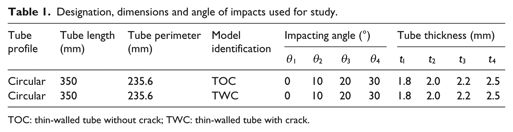
TOC: thin-walled tube without crack; TWC: thin-walled tube with crack.
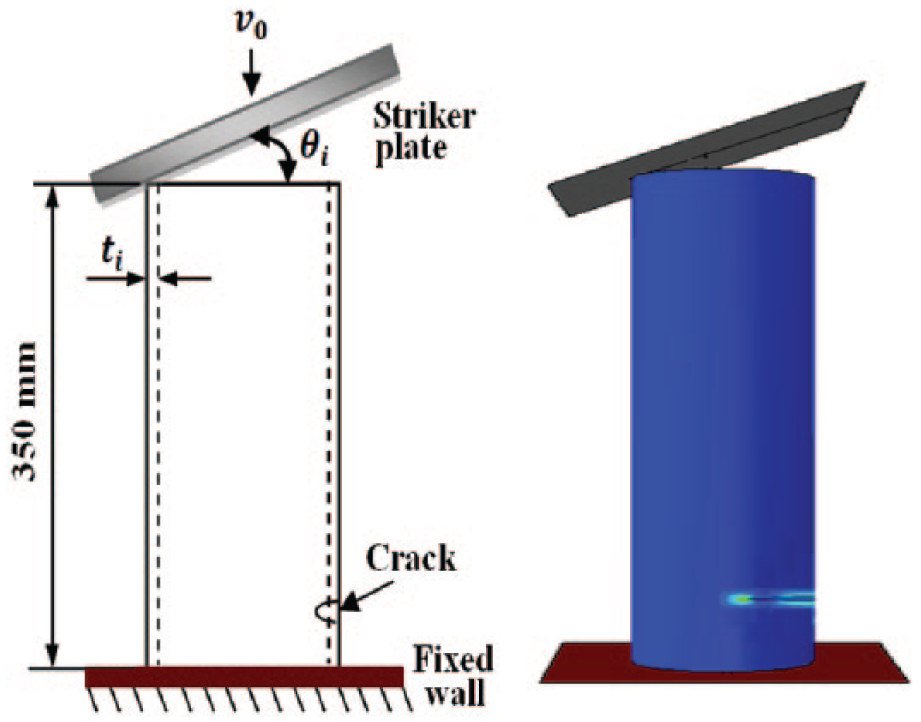
Schematic of modelled circular thin-walled tube set-up with crack at the distal end and tube subjected to oblique impact loading.
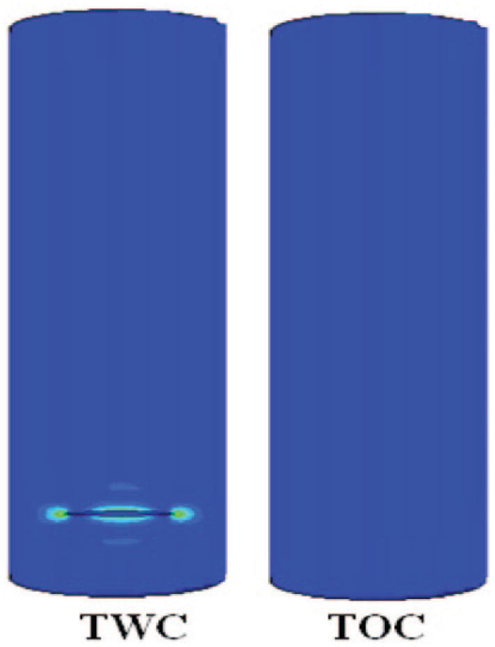
Representation of the two modelled thin-walled tubes used for study.
Material property
The material used for this study is made from A36 steel hot rolled carbon and it is strain rate sensitive with a dynamic flow stress

The Johnson-Cook constitutive model introduces the reference strain rate
Material properties for the A36 steel hot rolled carbon.

Extended finite element method (X-FEM) formulation of cracked thin-walled tube
In the traditional FEM, the modelling of crack can be computationally burdensome and generally inaccurate. This is because both the crack and the boundary of the mesh surrounding the crack must conform to each other. To achieve this, the material has to be continuously re-meshed until all the crack paths on the material are completely conformed to the boundaries of the finite element mesh. However, the X-FEM has become popular as an accurate and less burdensome numerical method for modelling cracks in two-dimensional (2D) and three-dimensional (3D) structures. In this method, the finite element meshes does not necessarily conform to the path of the crack (Möes et al., 1999). Both the mesh and the crack are completely independent of each other. Figure 3(a) shows the boundary of the unstructured meshes conforming to the crack path using the traditional FEM. In Figure 3(b), the X-FEM solution was applied and it can be observed that the boundary of the meshes does not necessarily conform to the path of the centre through crack. Only one simulation is run to generate the mesh and obtain accurate, approximated solution. The X-FEM solution enriches the finite element or mesh free approximation by adding new functions through the concept of partition of unity (Duarte and Oden, 1996; Melenk and Babuska, 1996). Moreover, X-FEM has been used to analyse the interaction of main crack and microcracks (Wang et al., 2016). In this study, the centre through crack which is located at the distal end of the circular thin-walled tube was modelled using the X-FEM as shown in Figure 4. The displacement approximation for this particular stationary crack is generally expressed as (Fleming et al., 1997)

where

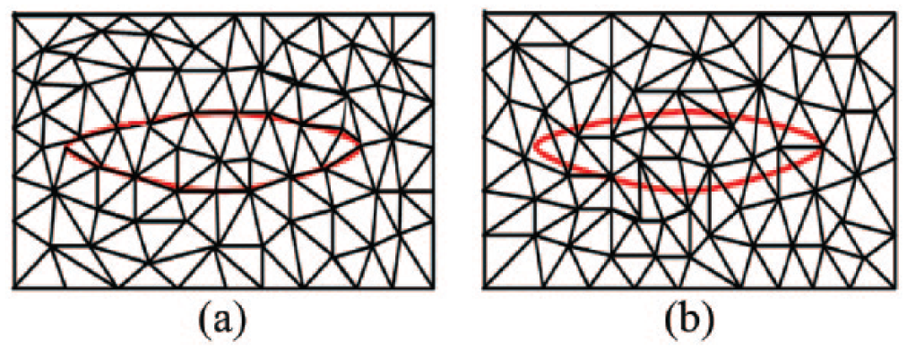
Unstructured meshes with centre through crack (a) finite element method – conforming meshes and (b) extended finite element method – nonconforming meshes.
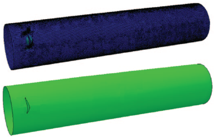
Three-dimensional X-FEM and geometric model of a centre through crack at the distal end of circular thin-walled tube.
The first term on the right-hand side of equation (2) is all nodes, the second term applies to nodes whose shape function support is cut by the crack interior and the third term is applicable to nodes whose shape function support is cut by the crack tip. Figure 5 represents the crack portion of the circular thin-walled tube domain. At the crack tip

where
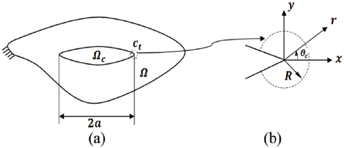
Body of the circular thin-walled tube showing the (a) crack domain Ωc and (b) coordinate system at the crack tip
In this study, the X-FEM model was applied and specified on the crack location with a crack length
Structural crashworthiness indicators
To assess the crushing performance of the two modelled thin-walled tubes, certain crashworthiness indicators must be defined. First, during the dynamic crushing of the tubes, the energy absorption capacity is calculated by simply integrating the crushing force

The maximum load
Another useful indicator which is in relation with the energy absorption capacity is the mean crushing force (MCF). It is defined as the total energy absorption divided by the crushing displacement of the tube given as

The crashworthiness indicator that relates both the peak force and the MCF is the CFE. It is defined as the ratio of the MCF to the peak crushing force and expressed as

A number of researchers have shown that a high CFE results in better performance of the energy absorbing tubes (Alia et al., 2014; Fang et al., 2015b; Taştan et al., 2016). Lower CFE value depicts high peak crushing force and greater possibilities of potential damages during crash incidence. It is therefore of utmost importance to keep it high during the design of thin-walled tubes used as energy absorbers.
In the analysis of the crashworthiness performance, the measure of the capability of the energy absorbed material is taken into consideration. This is in relation to the crashworthiness indicator called the SEA. It is the energy absorption per unit mass of the crushed tube

The absorber mass of the tube is a significant factor that affects the SEA and should be decreased so as to obtain higher values of SEA.
In this study, the numerical analysis of the major crashworthiness indicators for idealized tube without crack, finite element tube without crack and finite element tube with crack was performed. The exact solution of the idealized tube is compared with the approximate solutions of the finite element tubes with and without crack.
Numerical modelling and validation
Crushing parameters for idealized thin-walled tube
Consider the one complete folding process of the circular thin-walled tube section as shown in Figure 6. A striking plate moving with an initial velocity

where

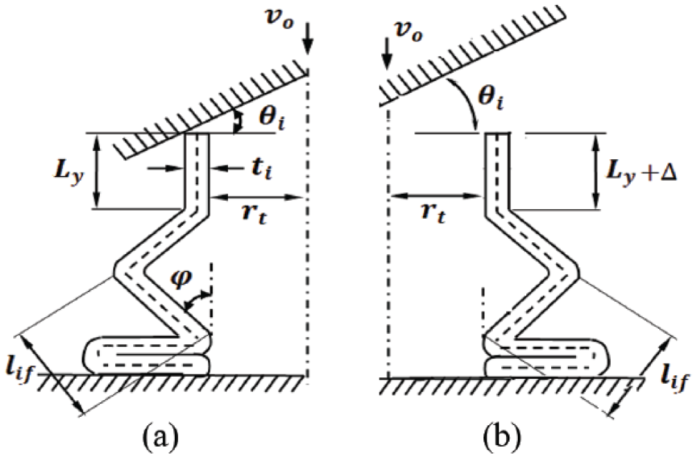
Idealized circular thin-walled tube sections depicting non-axisymmetrical mode for one complete folding process when subjected to oblique impact loading condition (a) axial length
For
In Figure 6, during the collapsed process, the folding angle

where

where
To obtain the MCF, from Figure 6, under axial impact, the force due to the plastic collapsed moment is given as

where

Substituting equation (14) into equation (13) gives

or

Since the material is strain rate sensitive, the dynamic speed impact behaviour of the metallic material is modelled by the Cowper–Symond constitutive equation which is obtained from equation (12) as

Multiplying equation (15b) by equation (16) gives the

For reasonable approximation, equation (17) is multiplied by a factor of 1.45 to give

From the plastic strain rate, the axial impact velocity at the end of the circular thin-walled tube is influenced by the angle of impact the striker plate makes with the thin-walled tube. Therefore, under various oblique loading conditions, the MCF can reasonably be approximated as (Isaac and Oluwole, 2018)

The value of the dynamic flow stress for mild steel is taken as 250 MPa (i.e.
Finite element modelling and mesh convergence
The crushing response of the modelled circular thin-walled tube was predicted using the non-linear finite element code Abaqus/Explicit. Dynamic crushing of the tube with or without crack results in non-linear effects of large deformation and displacement. The finite element type used for the thin-walled tube is the S4R element. This is a four-node continuum shell element used to model the tube thickness with a Simpson integration rule and thickness integration points of five along the element thickness of direction. Convergence study to obtain suitable mesh sizes was carried out for both tubes with and without crack. Figure 7 shows the effect of mesh refinement on the deformation mode of TWC and TOC configurations under 30° impacting angle. Generally, mesh refinement produces better energy absorption results. However, a point is reached where further mesh refinement gives no significant increase in the energy absorption result. In Figure 8, eight mesh sizes ranging from 0.3 to 1.0 mm at intervals of 0.1 mm were investigated for the two different configurations under 30° impacting angle as represented in Table 3. Convergence commenced from 5497 up to 9703 number of elements for TWC configuration while it commenced from 3294 up to 9670 number of elements for TOC configuration. The mesh sizes in the range where convergence occurred for the two configurations were from 0.3 to 0.6 mm. Therefore, performing mesh convergence study ensures correct and suitable mesh sizes that produce accurate results within acceptable and satisfactory computational time.
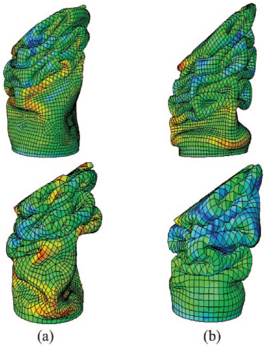
Effect of mesh refinement on the collapsed mode. The mesh size for the upper tubes is 0.3 mm while that for the lower tubes is 0.5 mm of tube thickness
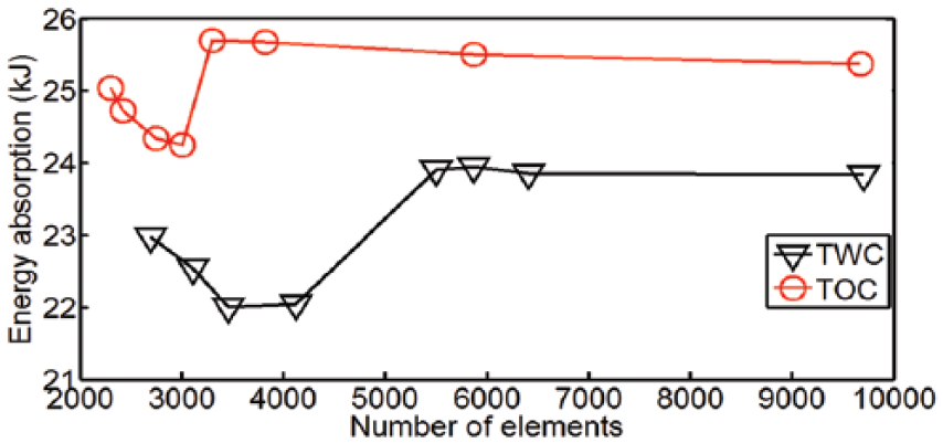
Eight-point convergence curves for TWC and TOC configurations of tube thickness
Relationship between mesh size and number of elements for two different configurations in this study.
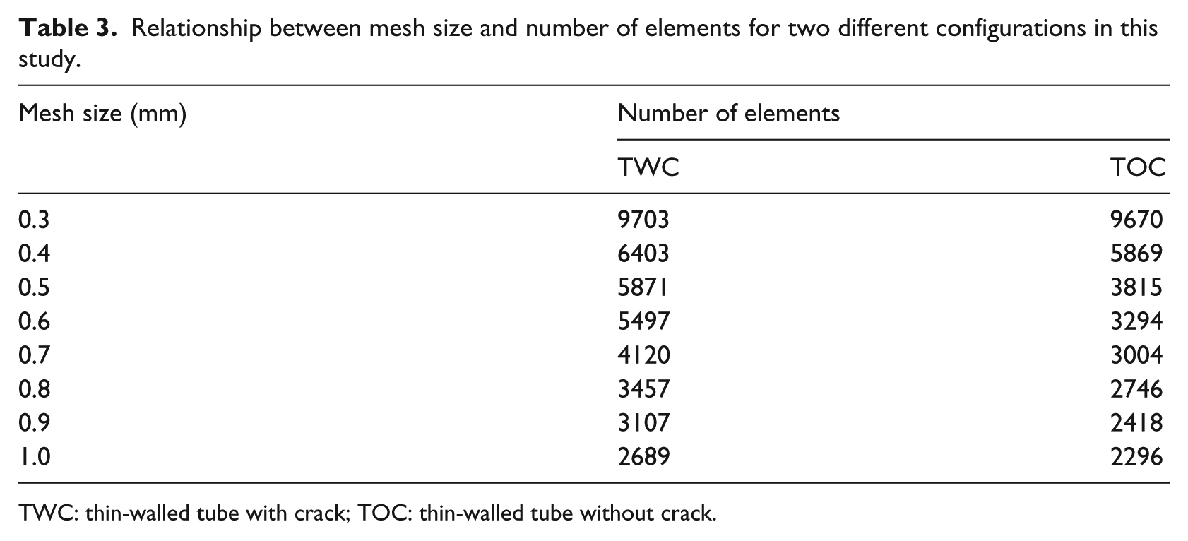
TWC: thin-walled tube with crack; TOC: thin-walled tube without crack.
The more number of elements generated by the tube with crack is due to finer elements generated around the crack tips. These finer elements around the crack tip help to effectively capture the crack behaviour during the deformation process. A 3D discrete rigid shell planer was used to model both the striker plate and the fixed wall and therefore does not require to be meshed to perform the finite element simulation. The deformation process requires a general contact interaction which allows contact between the Lagrangian surface and Eulerian material. A self-contact is also assigned to the tube so as to account for all possible self-interactions and avoid interpenetration of folding of the tube during the collapsed process. The self-contact interactions describe different contact between the various parts of the thin-walled surface such as the interaction between the entire tube surface and the crack surface. The self-contact was modelled by ‘Hard’ contact pressure over-closure relationship. To make the thin-walled tube, striker plate and fixed wall a continuous interaction system, a tie constrain was used. The system interaction was defined by surface-to-surface contact interactions and it describes contact between the thin-walled tube and the rigid surfaces such as the rigid wall and the striker plate. Moreover, the thin-walled tube was modelled as finite sliding penalty for the contact surfaces. The value of the Coulomb friction penalty coefficient is 0.2 (Ahmad and Thambiratnam, 2009).
Finite element model validation
While the centre through crack introduced at the distal end of the thin-walled tube was successfully initiated using the X-FEM approach, the centre through crack on the thin-walled tube was intractable, making it a major drawback to the analytical solution of the idealized thin-walled tube. Hence, the exact solution of the idealized crushed TOC (i.e. the theoretical formulation in section ‘Crushing parameters for idealized thin-walled tube’) is used to compare the finite element solution without crack. Figure 9 represents a comparison of the MCF and their corresponding energy absorption of both the idealized and finite element solutions without crack initiation and under different impacting angles. The exact solutions of the idealized circular tube at different tube thickness subjected to different impacting angles can be seen to verify the finite element approximated solutions of circular tubes without crack initiation. The results of the MCF and energy absorption obtained from these two solutions are further used to compare the approximated solutions of the finite element crushed TWC.
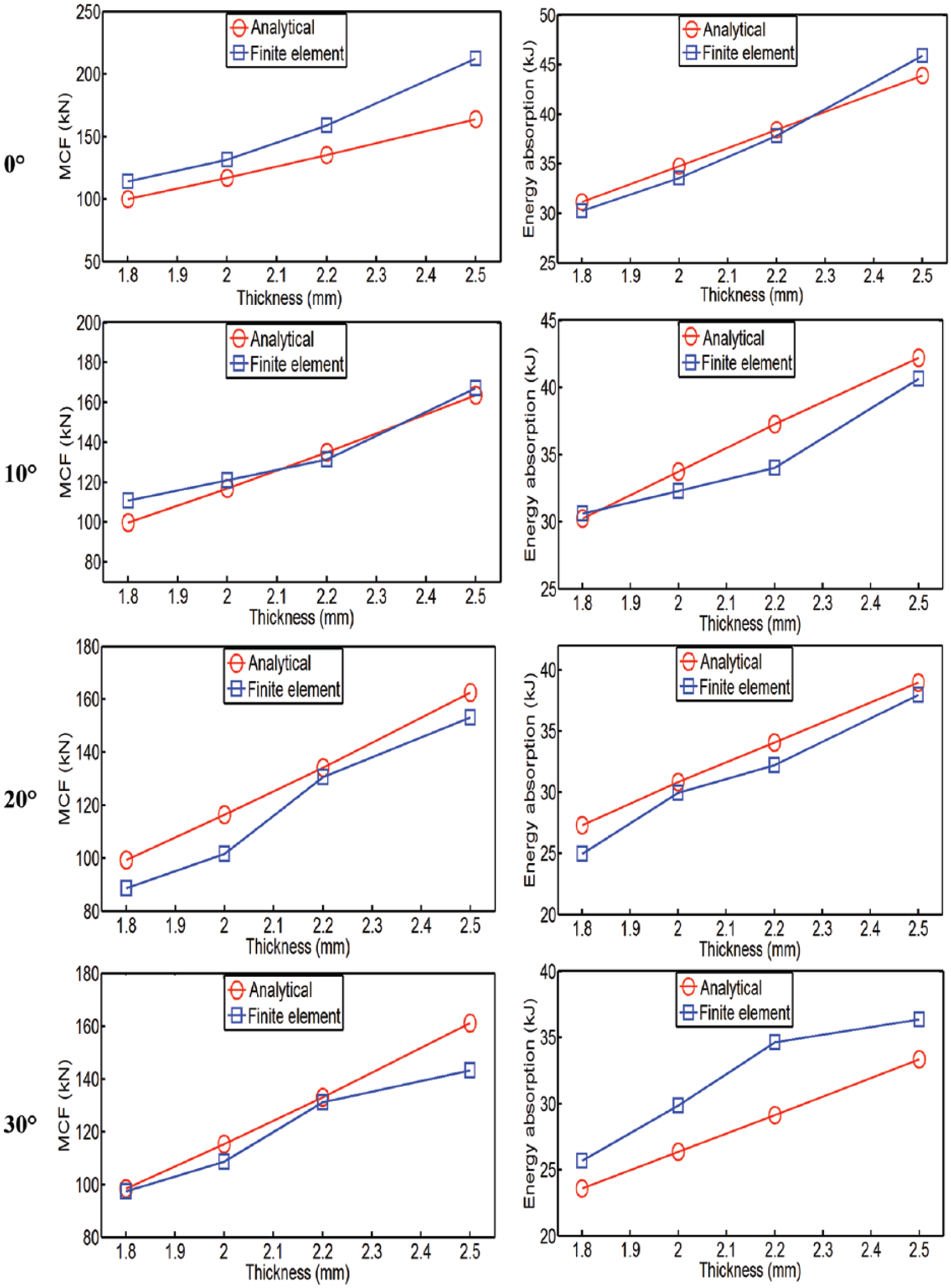
Analytical and finite element comparison of the mean crushing force and total energy absorption at different impacting angles
Numerical results and discussion
Deformation mode and force-displacement history
Figure 10 shows the deformation modes for TOC, damage morphologies for TWC and their corresponding force-displacement curves under various impacting angles. At impacting angle of 0°, the collapsed mode of TOC is axisymmetric or concertina. For this type of collapsed mode, regular pattern of peak forces can be observed in the force-displacement history. However, the collapsed mode of TWC is diamond or non-axisymmetric and their subsequent pair of peak forces are erratic or irregular. Moreover, at this 0° angle of impact, it is evident that folding commences at the distal end of both tubes. It is also seen that the initial peak force is higher than the subsequent pair of peak forces. At increasing impacting angles, the initial peak force is seen to be lowered than their subsequent pair of peak forces. On the collapsed tube, folding is seen to start at the impacting surface. The tube without crack is susceptible to bending with increase in impacting angles and the force-displacement diagram becomes erratic. Also, the initial peak force is lower than the subsequent pair of peak forces. For the tubes with crack, one observes very little bending during the deformation process. The bending reduction of TWC tube profile gives an advantage of a higher crushing force efficiency over TOC tube profile. However, the highly non-linear behaviour due to the initiation of the crack on the tube produces erratic responses and consequently lowers both the initial peak force and energy absorption capacity.
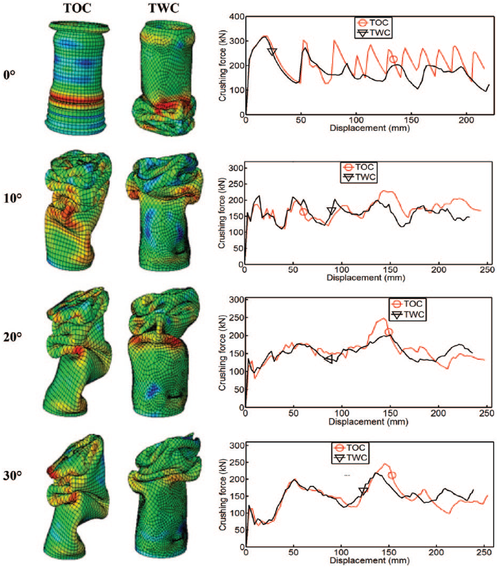
Collapsed mode of thin-walled tubes with and without crack of thickness
Stress–strain relationship
Figure 11 compares the finite element prediction of the stress–strain curves for TOC and TWC tube profiles of thickness
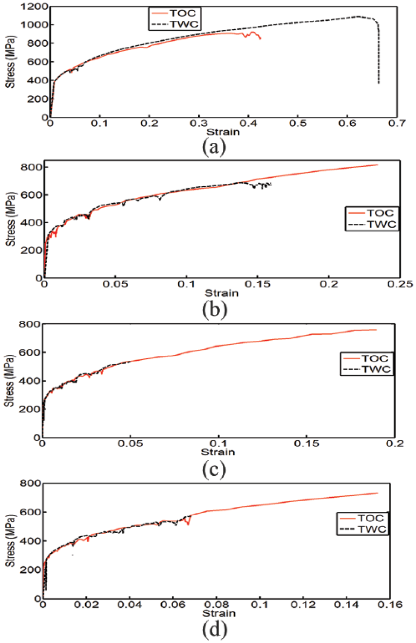
Stress–strain relationship of deformed circular thin-walled tubes with and without crack at different impacting angles (a) 0°, (b) 10°, (c) 20° and (d) 30°.
Effect of tube thickness and crack initiation
Thickness of the thin-walled tube plays a vital role to obtaining the initial peak force. In Figure 12, it is evident that with higher tube thickness, the initial peak crushing force increases. Moreover, more serrations develop with higher tube thickness. With fewer serrations, better crushing performance are obtained. A careful study shows that crack initiation on the thin-walled tube causes the initial peak force to increase as shown in Figure 12(b). At an approximate displacement of 2 mm for the different tube thickness, the initial peak forces for the tube with crack are seen to be higher than the initial peak forces of tubes without crack. The increase in initial peak force for the tubes with crack contributes to why their energy absorption capacities are lower than those without crack initiation. Moreover, one of the possible reasons for the increased initial peak force of TWC is the uneven distribution of stress around the tube during initial impact. Stress tends to concentrate more at the crack tip locations. It is therefore important to minimize the initial peak force during design. This can be achieved by introducing initiators or triggering mechanisms which help to raise the initial stress during loading and also reduce the effect of the transfer of load to the entire structure. Also, it is observed that more serrations are found for tubes with crack. The more the number of serrations the less stable the collapsed structure. The effect of crack initiation on TWC tube profiles, therefore, makes them to have less stable collapsed mode than the TOC tube profiles. Tube thickness at
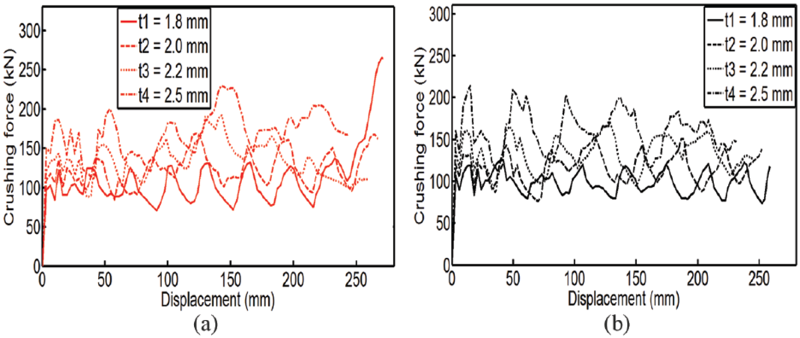
Crushing force versus displacement history showing the effect of tube thickness for (a) TOC tube profile and (b) TWC tube profile.
Energy absorption characteristics
The energy absorbed by the thin-walled tube along its length of deformation during and after impact is represented in Figure 13. These diagrams depict the energy-displacement comparison between TOC and TWC of tube thickness
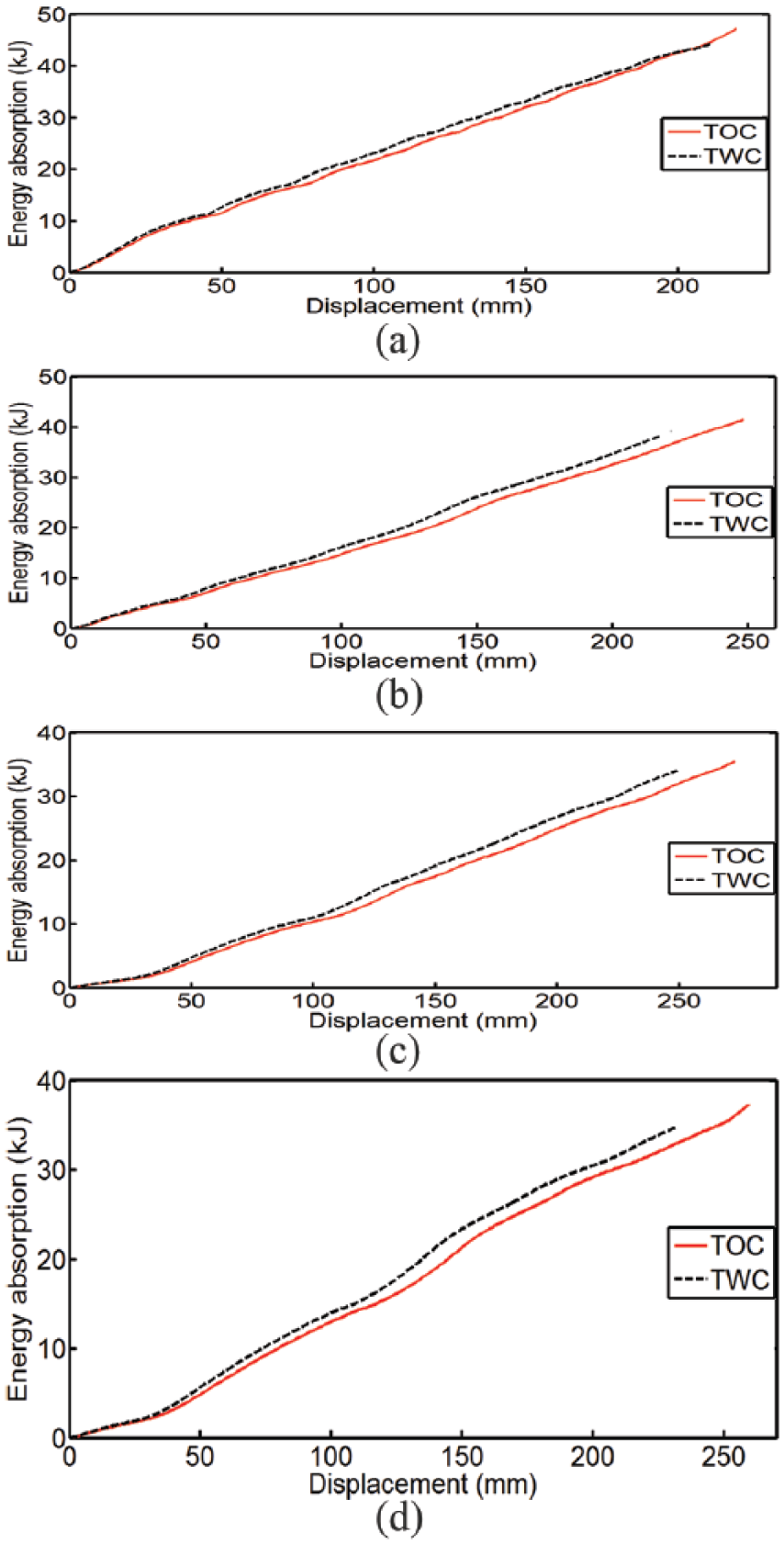
Energy absorption versus displacement characteristics of TOC and TWC profiles of tube thickness
Effect of crack size and location on tube
A further study is carried out to investigate the influence of crack size and location on the TWC tube profile. The crack is first located at the distal end of the tube and is designated as ‘Bottom’. Crack placed at the middle position of the tube is designated as ‘Centre’ while the crack placed at the top end of the tube is designated as ‘Top’ as represented in Figure 14(a). As the position of the crack moves from the distal end to the top end of the tube where the moving plate strikes it, the total energy absorption capacity slightly reduces. The reason for the energy reduction is because of the less contribution of the tube length to plastic deformation as the crack approaches the top of the tube. In Figure 14(b), the total energy absorption of TWC profile with crack at bottom, centre and top locations are 23.91, 23.01 and 22.17 kJ, respectively. Moreover, their initial peak forces were observed to be approximately the same. However, with increasing crack size and at the same crack location, the initial peak forces of these tube profiles varied. The longer the crack, the higher the initial peak force and lower the energy absorption capacity.
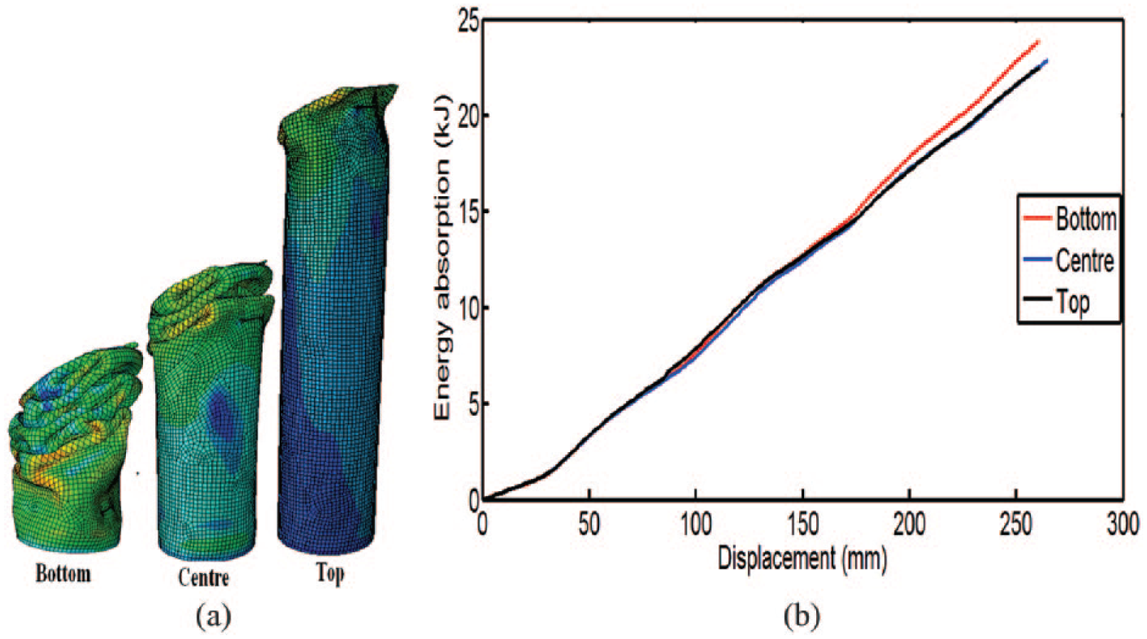
Influence of crack location for TWC profile of tube thickness
SEA
In all cases, the SEA of TOC tube profile is higher than TWC tube profile as represented in Figure 15. This is because after the crushing process, it was observed that the crushed mass of the tube with crack was slightly higher than those without crack. However, the mass of the tube before and after the plastic deformation is negligible as compared with the mass of the striker plate. It is evident that at impacting angle of 0°, the SEA increases with wall thickness for both TOC and TWC. However, as the impacting angle increases, the SEA shows strong likelihood to decrease. The SEA of the TOC of tube thickness
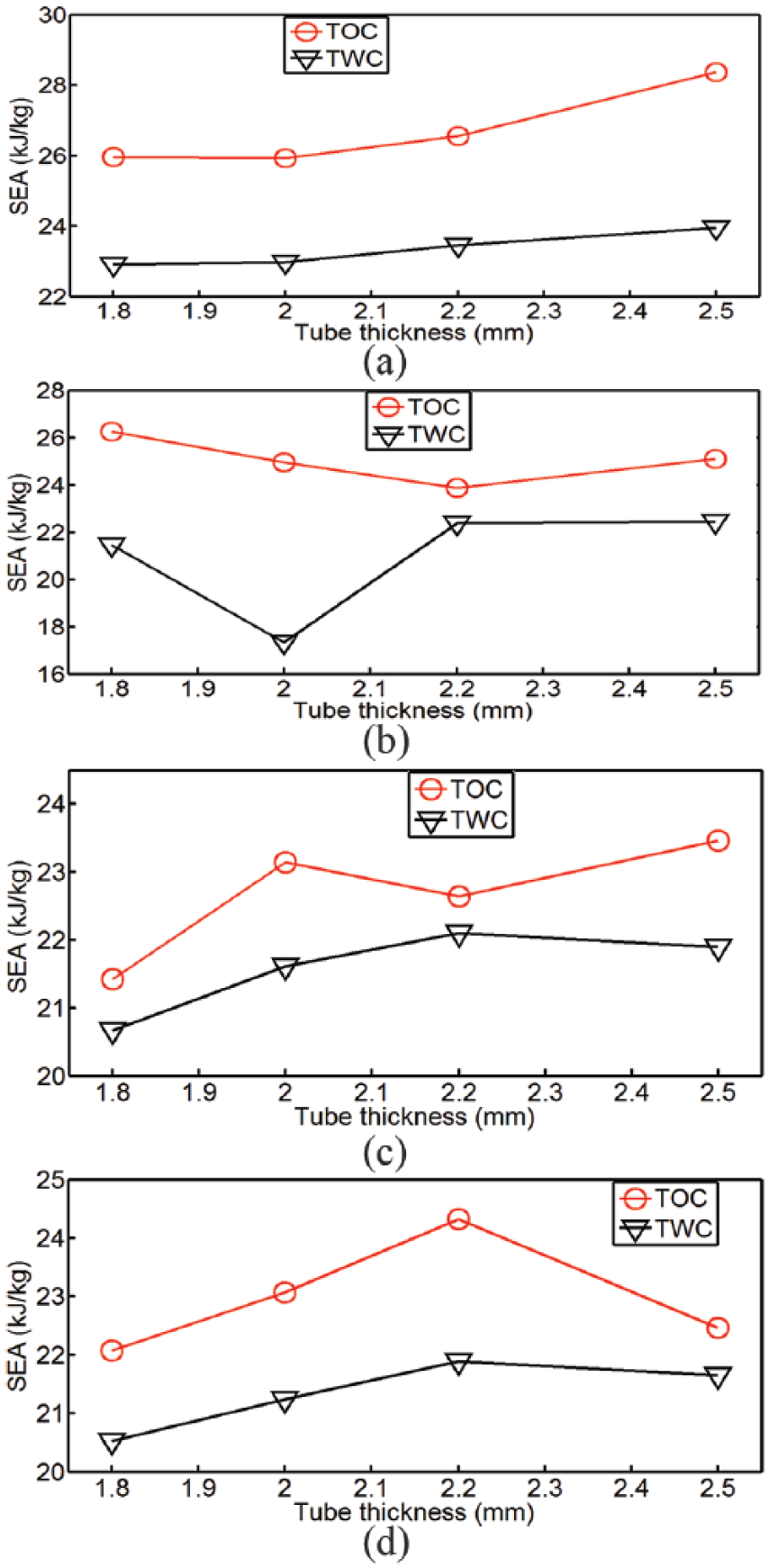
Specific energy absorption comparison between TOC and TWC profiles at different impacting angles (a) 0°, (b) 10°, (c) 20° and (d) 30°.
Summary of crashworthiness parameters
Major crashworthiness parameters such as the total energy absorption
Summary of the crashworthiness parameters comparison between TOC and TWC tube configurations.
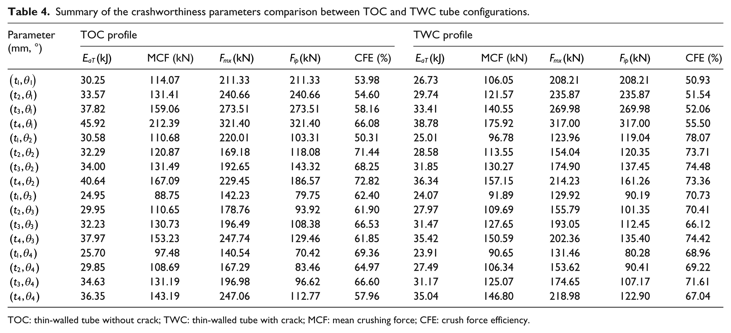
TOC: thin-walled tube without crack; TWC: thin-walled tube with crack; MCF: mean crushing force; CFE: crush force efficiency.
Analytical and finite element results comparison
In section ‘Finite element model validation’, the analytical solution of idealized circular thin-walled without crack was used to verify the finite element approximations of the TOC. In this section, a comparison of the MCF and the energy absorption of the finite element approximations of cracked thin-walled tube (TWC-FE) with both the tube without crack (TOC-FE) and the idealized tube without crack (Analytical) is performed. Figure 16 shows the energy absorption versus thickness of the thin-walled tube at all impacting angles used in this study. It is clear that the energy absorption capacities of TWC-FE are lower than TOC-FE while TOC-FE and Analytical show very close relationship with each other. Also, the MCFs for TOC-FE are much greater than TWC-FE at 0° impacting angle as depicted in Figure 17(a). With increasing impacting angles, good agreement of the MCF for the three numerical modelled circular thin-walled tubes is evident as represented in Figure 17(b) to (d). The numerical predictions of these major crashworthiness parameters reveal the undesirable effects of crack on energy absorbing circular tubes and also offer a guide for the design of an efficient circular thin-walled tube used as energy absorber for crashworthiness application.
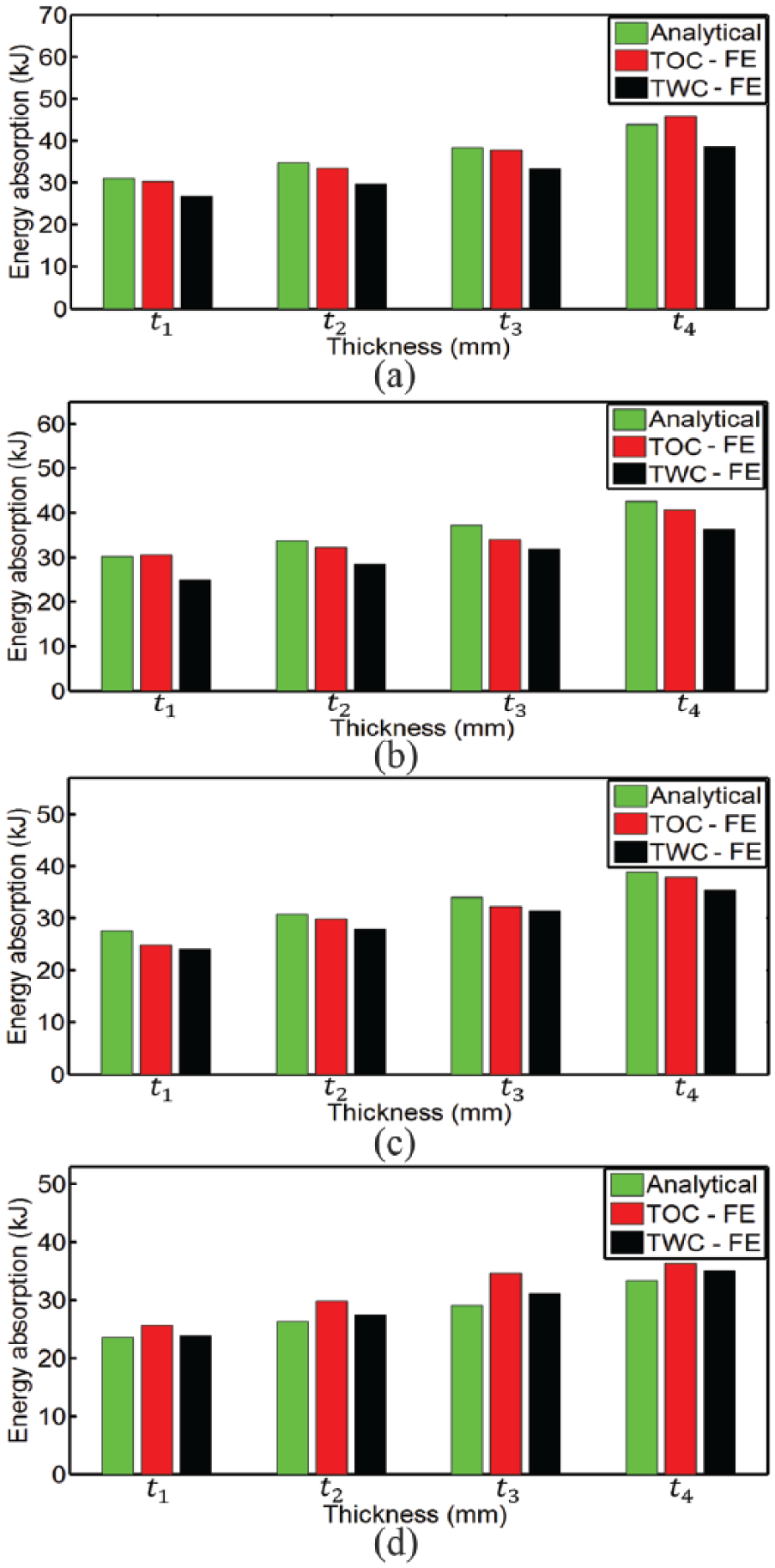
Summary of energy absorption comparison between analytical and finite element models for all tube thicknesses
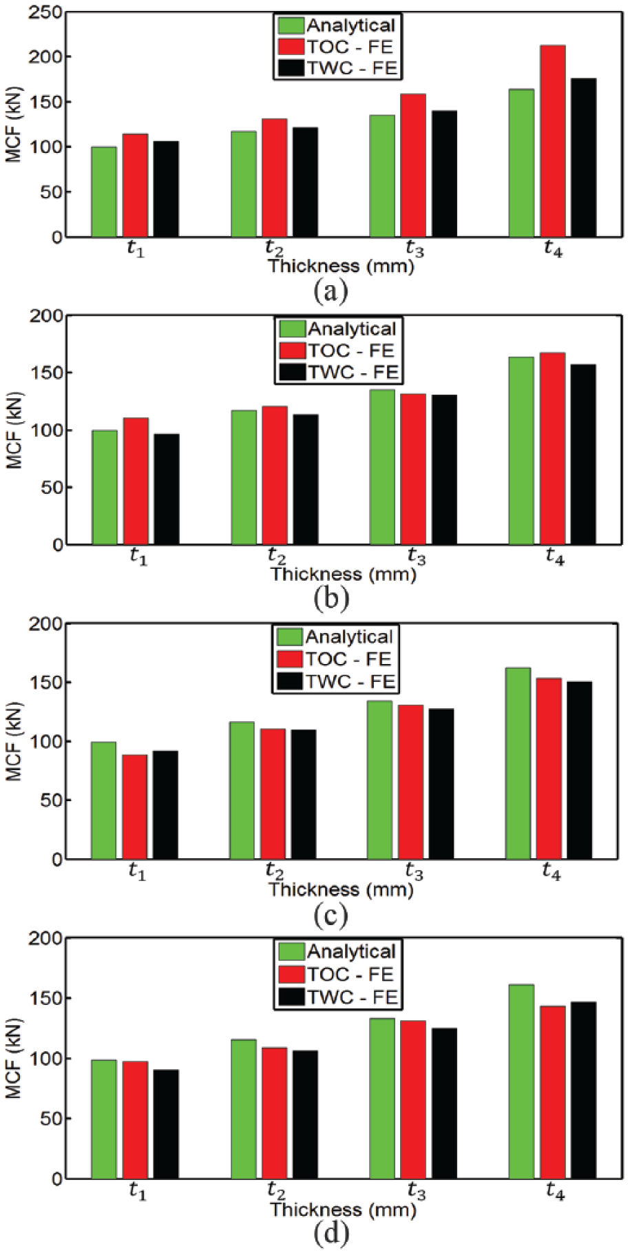
Summary of mean crushing force comparison between analytical and finite element models for all tube thicknesses
Reliability and accuracy of numerical solution
For the credibility of numerical solution, it is necessary that the material used for modelling is of the same material property, loading and parametric conditions of the material used for the experiment. These conditions influence the crashworthiness performance of the thin-walled tube significantly. Experimental result obtained under quasi-static loading produces a different result from numerical model when the tube is subjected to dynamic loading. In the latter case, higher energy absorption, MCF and other crashworthiness parameters are obtained. Where no experimental data are available to validate the finite element solution, it behoves to use analytical solution to verify the finite element approximation. In this study, the analytical solution of the total energy absorption of the circular thin-walled tube (TOC) was predicted in section ‘Crushing parameters for idealized thin-walled tube’. A summary of the percentage error of the total energy absorption
Percentage error of the total energy absorption comparison between analytical and finite element solutions.
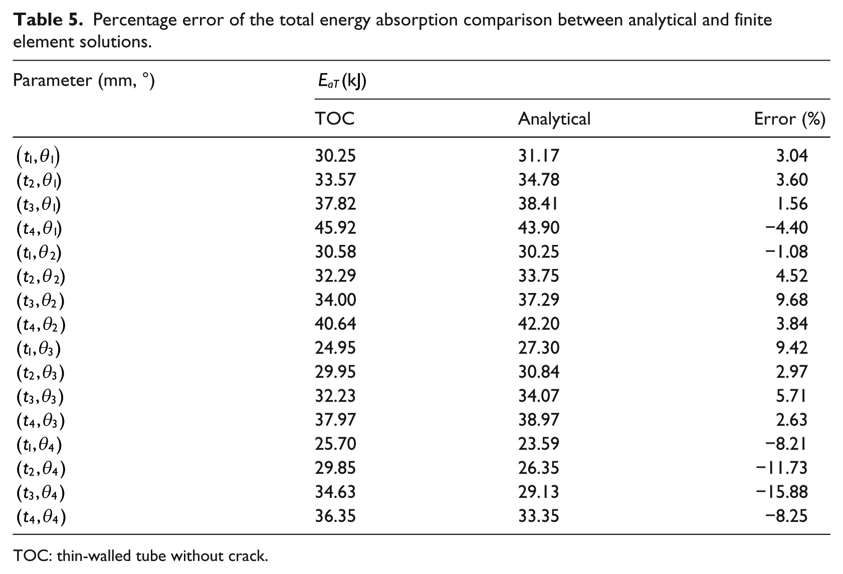
TOC: thin-walled tube without crack.
Summary and conclusion
In this study, the effect of crack initiation on the crashworthiness performance of circular thin-walled tubes subjected to various loading conditions was investigated numerically. First, an analytical solution for circular tubes without crack was established and the results were used to verify the finite element approximations of circular TOC under the same parametric and loading conditions. The analytical solutions show good agreement with the finite element approximations. Crack was then initiated at the distal end of the circular thin-wall tube (TWC) using the X-FEM. The results of TOC and TWC profiles were compared with each other.
Based on the findings of this study, the following conclusions can be drawn:
During oblique crash case, the crushing force efficiency of circular TWC initiation is higher than those without crack. For tube thickness of 2.5 mm and impacting angles of 10°, 20° and 30°, the CFE of TWC are 73.36%, 74.42% and 67.04%, respectively, while that of TOC are 72.82%, 61.85% and 57.96%, respectively. The increased CFE of the TWC is due to the ability of the tube to withstand bending during the deformation process and this also causes a reduction in the MCF.
However, in terms of the energy absorption, the tube without crack gives higher results than the tube with crack. Also, better results in the SEA were obtained by the tube without crack. The simulation results show that for tube thickness of 2.5 mm and at impacting angles of 0°, 10°, 20° and 30°, the SEA for TOC are 28.37, 25.10, 23.47 and 22.47 kJ/kg, respectively, while the SEA for TWC are 23.96, 22.45, 21.89 and 21.66 kJ/kg, respectively.
In spite of the improved CFE of cracked thin-walled tubes during oblique loading, the reduction in energy absorption and SEA make them less attractive for energy absorbing structures. During fabrication of circular thin-walled tubes, discontinuities may be introduced. Therefore, the need to test these tubes for any defect or small crack is of utmost importance. This will help to minimize uncertainty of the energy absorbing structure during crash operation and ensure maximum crashworthiness performance.
The higher crashworthiness performance as observed by the TOC profile gives it desirable advantage as protective structure over the TWC profile.
The study therefore shows how the presence of cracks in energy absorbing thin-walled tubes contributes to their overall crashworthiness performance.
Footnotes
Declaration of conflicting interests
The author(s) declared no potential conflicts of interest with respect to the research, authorship, and/or publication of this article.
Funding
The author(s) received no financial support for the research, authorship, and/or publication of this article.
