



Abstract
High-lift devices of transport aircraft reshape the wing in order to increase the lift of the aircraft during certain portions of flight. In order to increase its reliability, large transport aircrafts usually install the inter connection strut (ICS) as security devices. However, there are very limited publications on how to design the ICS, and how it works. There is a strong motivation for modeling and simulating the behavior of high-lift devices with ICS once failure happens and resulting design parameters. In this study, based on rigid-flexible coupling multi-body modeling technique, and dynamic response analysis of flap system under normal operation and failure state, a design method of ICS is proposed and the key parameters, that is, freely moving range and the mean crushing load of the energy absorber, are identified. The mitigation effect of ICS for actuator failure of flap system is clarified by analyzing the dynamic response of flap system with ICS. The results show that the ICS can reduce the peak driving torque of drive strut by 45.3%, and the unexpected rotation of the flap decreases by 66.2% after actuator failure happened.
Keywords
Introduction
The flap system can increase the maximum wing lift of aircraft during take-off and landing process by varying both wing area and wing curvature. The flap system has different working positions corresponding to different flight phases, and there are usually two actuators driving one flap during the position transition. For the flap system, when one of the actuators fails, the other may generate much high stress on the flap system. Meanwhile, an unexpected movement of the flap may disturb the aerodynamic configuration of the aircraft wing (Rudolph, 1996; Vasista et al., 2019). The actuator failure is one of the critical failure cases of the flap system (Winter and Woernle, 2013)
To improve the reliability of the flap system, large transport aircrafts usually install interconnection strut (ICS) as the security device. The ICS provides an alternative load path between flaps; meanwhile, it limits the unexpected movement of the flaps maintaining the aerodynamic configuration of the aircraft wing.
Since 1980s, the researchers have designed several kinds of ICS. The ICS can be divided into three types: the single rod type, the cylindrical pair type, and the multi-rod type. Breedveld and De Haan, (1985) in 1985 designed a kind of single rod type flap connecting device, which only connected adjacent flaps with connecting rods to limit the large relative movement between flaps. In the same year, Kurt et al. (1985) invented another kind of cylindrical pair type flap connecting device with energy absorbing element. Other than connecting adjacent flaps, this device can also absorb the impact energy. Poppe and Auhagen, (2009) designed a multi-rod type ICS, which can be suitable for the flap system with large wingspan. Versluis, (2013) proposed an improved cylindrical pair type ICS in 2013, which had two energy absorbing elements working under both the compression and tensile condition, respectively. Huang et al. (2017) presented a cylindrical pair type ICS using expansion tubes as energy absorber. However, the researches about the dynamic analyses of the flap system and the design methods of ICS are relatively less. NASA report (Rudolph, 1996) described the key components and the typical motion of the flap system. Then, Zierath et al. (2009) established the multi-body dynamic model of the flap system and analyzed the system responses of flap system under different working condition. After that, Winter and Woernle, (2013) simulated the flap system under a critical failure case. What’s more Huang, (2020) added ICS to the flap system considering the ICS as a linear spring without energy absorber.
To identify the mitigation effect of the ICS of the flap system under actuator failure case and provide a theory base for the future design of the ICS, in this study, we firstly establish the rigid-flexible coupling multi-body model of the flap system, and conduct dynamics analysis of the flap system under normal operation condition and failure condition. Then, the design method of the ICS is proposed and the key parameters are determined. Finally, the torque, movement, and stress of the flap system with and without the ICS under actuator failure is evaluated to clarified the mitigation effect of the ICS.
Rigid-flexible coupling multi-body modeling of the flap system for large transport aircraft
Rigid-flexible coupling multi-body modeling of the flap system
The flap system in this study consists of two pieces of flaps and four track stations, as shown in Figure 1 Each track station, named i# track station (i = 1, 2…4), has an actuator, a track beam, a drive strut, a link, and a carriage, as shown in Figure 2. In the flap system, the actuator rotates the drive strut and the link driven by the drive strut forces the flap and carriage moving along track beam. Flap system. I# Track station.
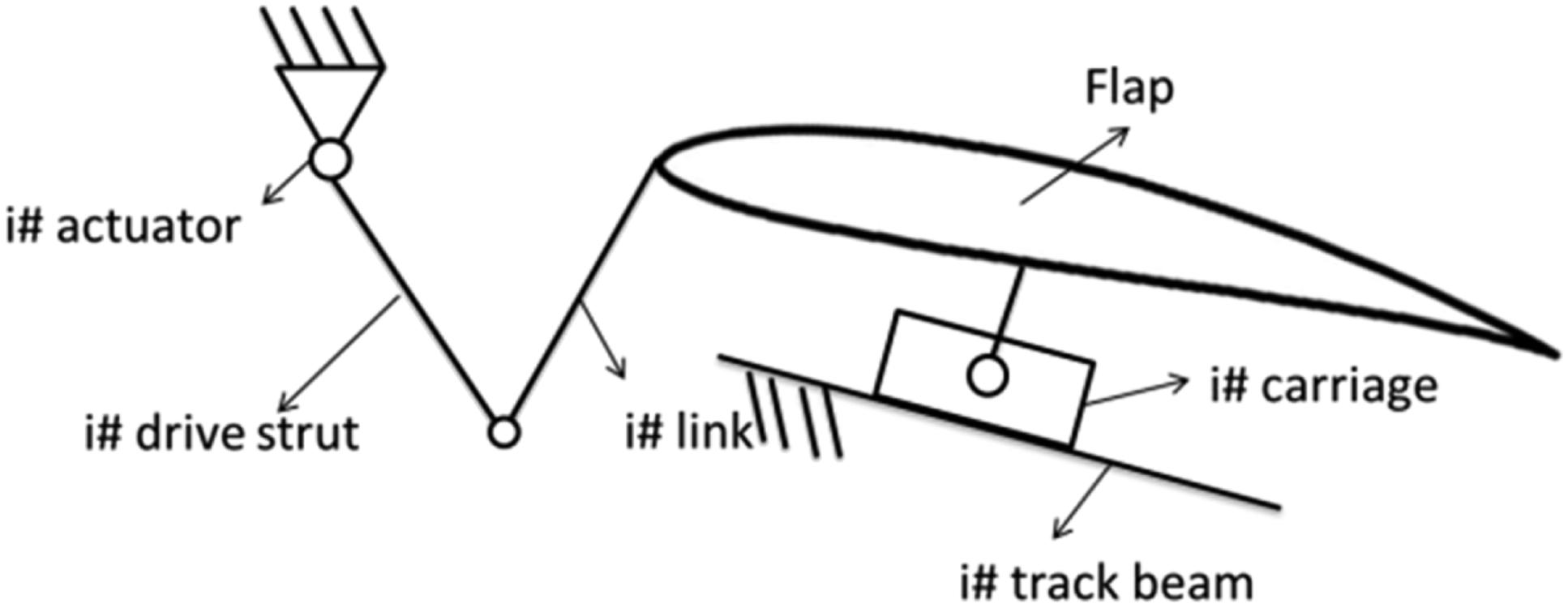
During the moving process, the deformations of the flap system cannot be neglected. Therefore, the rigid-flexible coupling multi-body modeling method should be used in simulating the dynamic process of the flap system considering both accuracy and efficiency. The rigid-flexible coupling multi-body dynamic modeling of the flap system consists of the following steps as shown in Figure 3, including the establishment of the geometry model, the flexibility of the model, and the set of the joints and aerodynamic loads. Rigid-flexible coupling multi-body modeling of the flap system.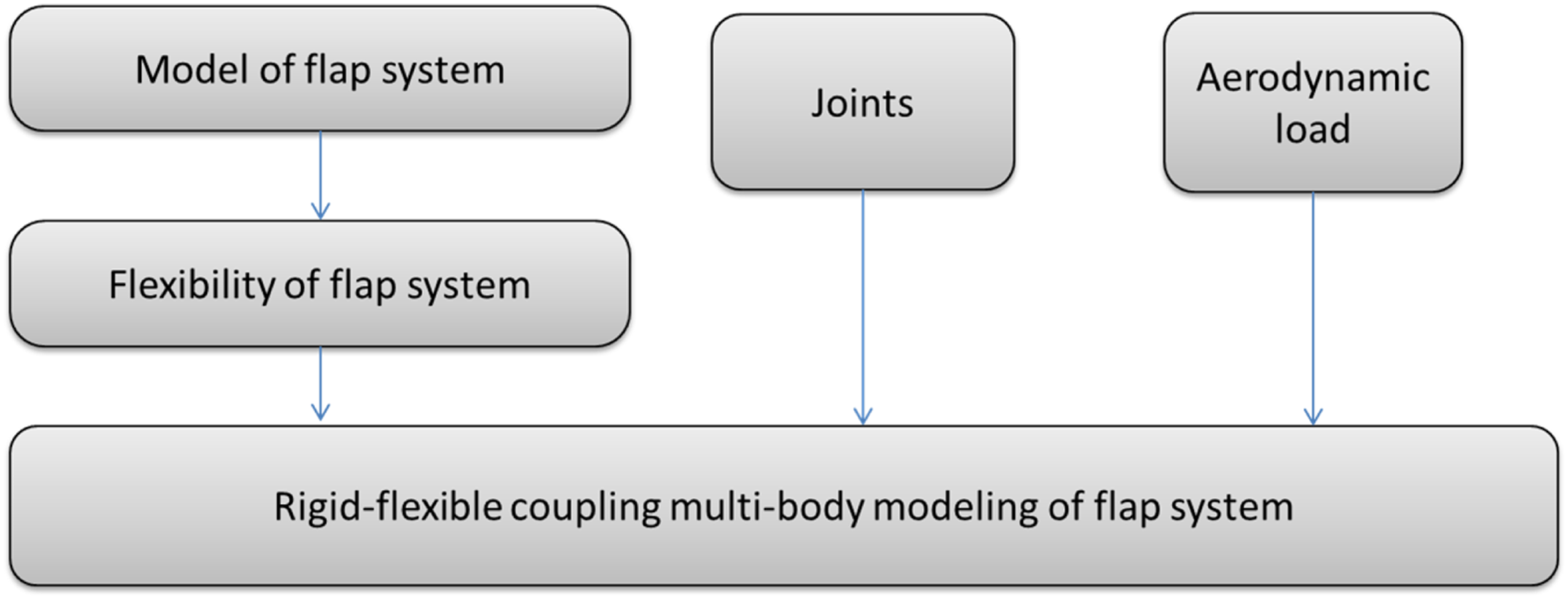
Flexibility of the flap system
In flap systems, the deformation of some components during the moving process has a great influence on the system responses. During the modeling of a rigid-flexible coupling multi-body system, these components will be considered flexible. In this consideration, the flap surfaces, drive struts, links, and track beams are treated as flexible components. The modal analysis is performed in CAE software NASTRAN. The modal information of these components is imported into MSC ADAMS software to establish the rigid-flexible coupling multi-body dynamic model.
Selected modal order for different components.

Aerodynamic load of the flap system
For the flap system, the aerodynamic load is distributed on the flap surface. Since the flap has been treated as a flexible body, the aerodynamic load should be applied at every element nodes of the flap surface. The aerodynamic loads on the outer flap surface at a given moment are shown in Figure 4 and the resultant forces of the aerodynamic loads on the inner flap and outer flap are given in Figure 5 (The loads are normalized with the same factor). It can be seen that the aerodynamic load in Y direction is much larger than those in X and Z directions. This means the most load borne by the flap system is lift, which meets the design principle of the flap system. Aerodynamic load on the outer flap surface at a given moment. (a) On inner flap (b) On outer flap. Aerodynamic loads on inner and outer flaps. (a) On inner flap; (b) On outer flap.

Joints
The components of the flap system have various relative movement relationships. In this study, the track beams are fixed, as shown in Figure 6(a). The drive struts are connected with links by revolute joints, as shown in Figure 6(b) and (c). The flaps are connected with carriages and links by spherical joints, as shown in Figure 6(d). As for the carriages, they are connected with track beams by translational joints, as shown in Figure 6(d). Joints on flap system. (a)Joints on track beam; (b) Joints on drive strut; (c) Revolute joints between drive strut and link; (d) Joints on carriage and flap.
Rigid-flexible coupling multi-body model of the flap system
The established model of the rigid-flexible coupling multi-body model for the flap system is shown in Figure 7. Rigid-flexible coupling multi-body model of the flap system.
The governing equation of the rigid-flexible coupling multi-body model of the flap system can be obtained based on the hybrid coordinate multi-body dynamic theory (Xu et al., 2019; Ahmed and Jalil, 2001; Bruni et al., 2020). For the ith component, for example, flaps, actuators, or track beams, in the flap system, its reference coordinates are shown in Figure 8. The global position vector of an arbitrary point P
i
on the component can be written as Reference coordinate.

The constraint equations describing the joint constraints and specified motion trajectories can be written in terms of the system generalized coordinates q as
Based on the hybrid coordinate multi-body dynamic theory (Tao et al.,2020; Fang et al.,2021), the governing equation can be expressed as
Dynamic responses of the flap system under normal operation or failure condition
Dynamic analysis of the flap system under normal operation condition
The dynamic responses of the flap system under normal operation condition are simulated using the MSC ADAMS software. The flap system is driven by rotation actuators with a constant angular speed. The positions and deformation contours of the flap system moving to 5 and 34 are given in Figure 9. The flap system at different attack angle. (a) 5°; (b) 34°
Figure 10 shows the torques calculated from this study and the measured torques from the previous experiment applied on the four drive struts. It can be seen from Figure 10(a) that the torques on four drive struts increase at the beginning. The maximum torque appears at 9.35 s. After that, the applied torque decreases. Only the torque on 3# drive strut increases again after 14 s. Comparing the torques on different drive struts, the maximum torque appears on 3# drive strut at 9.35 s. Figure 10(b) is the measured torque of the drive struts from technical report provided by the Commercial Aircraft Corporation of China. By comparing the calculated results with measured torque of the drive struts, it can be seen that a good agreement is achieved especially during the first 12 s. This paper focuses on the dynamic responses of the flap system around 9.35, so the model established in this study is effective. Simulated torques and measured torques on drive struts. (a) Simulated torques; (b) Measured torques.
Dynamic analysis of the flap system after actuator fails
Failure cases of the flap system.
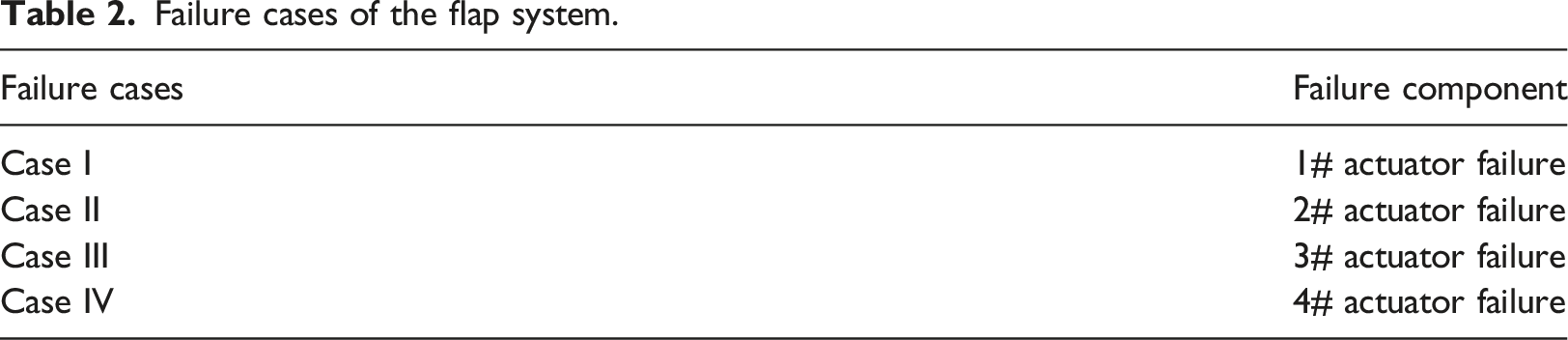
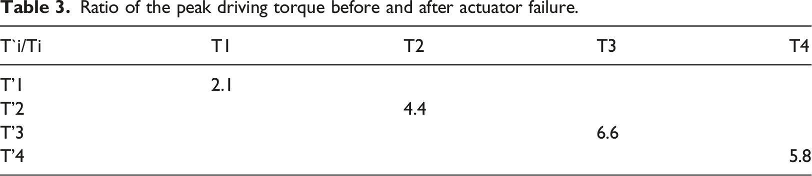
In the MSC ADAMS software, the actuator failure is simulated by deactivating the drive on actuator at the failure moment 9.35 s. The dynamic analysis of the flap system after actuator failure is carried out. Figure 11 shows the simulation result of driving torques on drive struts. It is seen that when one actuator of the flap fails, the driving torques on the other drive strut increases abruptly. The peak driving torques of the four drive struts after the actuator failure are T’1, T’2, T’3 and T’4, respectively; and the driving torques of the four struts before failure are T1, T2, T3, and T4, respectively. Then the ratio of the peak driving torque before and after actuator failure is given in Table 3. It can be seen clearly that the maximum increase amount of the torque happens in case III. The simulated torques of the actuator failure have same change tendency with Winter’s research (Winter and Woernle, 2013) validating the dynamic analysis of the actuator failure of flap system. Driving torques on drive struts under actuator failures. (a) 1# actuator failure; (b) 2# actuator failure; (c) 3# actuator failure; (d) 4# actuator failure. Ratio of the peak driving torque before and after actuator failure.
Besides the increase of applied torques on drive struts, the flaps will rotate relatively once the actuator failure happens. The rotation of flaps for case I, II, III, and IV are shown in Figure 12, respectively. The rotation of flaps for case I and case II are relatively small comparing those for case III and case IV. In case III, the outer flaps will rotate counterclockwise, shown in Figure 12(c); while the outer flap will rotate clockwise shown in Figure 12(d) for case IV. Thus, the collision between two pieces of flaps may happen; and the largest rotation of flaps happens in case III. Movement state of the flaps after actuator failures. (a) After 1# actuator failure; (b) After 2# actuator failure; (c) After 3# actuator failure; (d) After 4# actuator failure.
In summary, the actuator failure will not only cause an abrupt increase in the driving torques, but also result in large rotation of the flaps. The failure happened in 3# and 4# actuators will lead to different rotation direction of the outer flap. The case III is the most severe failure condition, due to the maximum driving torque and the largest rotation of flaps.
ICS design method
The ICS should be installed between the inner and the outer flaps, as shown in Figure 13(a), and a typical ICS configuration is shown in Figure 13(b). The flap system with the ICS and a typical ICS configuration. (a) The flap system with the ICS; (b) The ICS configuration.
As a recovery mechanism, two main features are considered in the design process of the ICS: the freely moving range to avoid disturbing the normal operating condition of the flap system, and the required energy absorption capacity under failure condition.
In order to design the ICS, firstly, the design requirement of the ICS is determined from the dynamic analysis of the flap system, and then the response curve of the ICS is calculated. Finally, the model of the flap system with the ICS is established and the simulation of the flap system with different ICS parameters are calculated and compared. The procedure is shown in Figure 14. The distance change between two end points of the ICS is as shown in Figure 15. Therefore, the freely moving range can be determined, which is from 30 mm to 10 mm. Flow chart of design of the ICS. Distance of two end points of the ICS.

The energy absorbed by the energy absorber in the ICS can be considered as the external work done by the mean crushing load (Jones, 2011). The rigid-flexible coupling multi-body model of the flap system with the ICS is established and the flap system with the ICS in case III, which is the most severe failure case, in different mean crushing loads, that is, 10 kN, 12 kN, 14 kN, 16 kN, 18 kN, and 20 kN, respectively, are simulated. Based on the law of conservation of energy, during the actuator failure, the energy equation of the flap system with the ICS can be expressed as
Simulation results of the ICS with different mean crushing loads.

Mitigation effect of the ICS for actuator failure of the flap system
The simulations of the flap system with and without the ICS under actuator failure conditions case III are implemented using the MSC ADAMS software to study the mitigation effect for actuator failure of the flap system. The peak driving torques on 4# drive strut, the distance change between two end points of the ICS, the maximum equivalent stress on each component, and the stress distribution on the flaps are compared. The peak driving torque on 4# drive strut with the ICS reduces by 45.3%, as shown in Figure 16, where M1 is the peak driving torques on 4# drive strut of the flap system with the ICS, while M2 is that of the flap system without the ICS. The similar change tendency of the driving torques between the results from Guelzau’s research (Guelzau, 2006) validates the simulation results of the driving torques. The compression amount of the flap system with the ICS reduces by 66.2%, and the oscillations of the flap system become lower with the ICS, as shown in Figure 17, where L1 is the maximum distance of the two end points of the ICS of the flap system with the ICS, while L2 is that of the flap system without the ICS. Comparing with the distance change of ICS in Huang’s research (Huang, 2020), the change of distance of the two end points of the ICS in this paper is similar. Thus, the simulation results of actuator failure of the flap system are reasonable and the unexpected rotation of the outer flap is limited by the installation of the ICS. Driving torque of drive strut. Distance of two end points of the ICS.

For the flap system with the ICS, the maximum equivalent stress on the outer flap reduces by 72.7% comparing to that without the ICS; and the maximum equivalent stress on the inner flap with ICS is larger than the stress on the outer flap without ICS, but it is still in a low level, shown in Figure 18(a). The maximum equivalent stresses on 1#, 2#, and 3# track beam remain unchanged, but the stress on 4# track beam reduces by 48.5%, shown in Figure 18(b). The maximum equivalent stress on the 3#, 4# links greatly reduces by 75% and 77.8%, separately, shown in Figure 18(c). This shows that a new load path is built between flaps and the load on the outer flap transfers to the inner flap, as shown in Figure 19. The installation of ICS redistributes the stress in the flap system. Maximum equivalent stress on main components of the flap system with and without the ICS. (a) Flap; (b) Track beam; (c) Link. The load distribution of flap system (a) Before actuator failure (b) After actuator failure.

The distribution of von Mises stress of flap surface is shown in Figure 20. The maximum stress of the outer flap without the ICS locates on the skin near the flap rib, as shown in Figure 20(a). However, the location of the maximum stress with the ICS of the outer flap moves to the front beam, as shown in Figure 20(b), which is benefit to the strength of the flap structure. von Mises stress contour of outer flap surface with or without the ICS. (a) Without the ICS; (b) With the ICS.
From the results above, the mitigation effect of the ICS for the flap system is obvious, once the actuator failure of the flap system happens. It can be found that the ICS can reduce the peak torque on the drive strut after actuator failure. Meanwhile, it can limit the unexpected rotation of the failure flap. Furthermore, the ICS can also decrease the maximum stress level of the flap system, and enhance the strength of the structure.
Conclusions
In this study, applying the rigid-flexible coupling multi-body modeling and analysis technique, the design method and the mitigation effects of the ICS for the flap system of large transport aircraft are investigated. The conclusions from this study can be drawn as follows. 1. The rigid-flexible coupling multi-body modeling method of the flap system with the ICS is establish and is validated through comparing the calculated driving torques on drive strut with the measured ones. 2. The design method of the ICS is proposed by combination of the dynamic analysis of the flap system and the energy absorbing design of the ICS. The two major factors for the design of the ICS are freely moving range and the mean crushing load. 3. For the mitigation effect of the ICS on the flap system after the actuator failure, the dynamic responses of the flap system with and without the ICS is implemented. The results show that the ICS can greatly reduce the peak torque on the drive strut by 45.3% when actuator failure happens, the ICS limits the unexpected rotation of the failure flap. Furthermore, it can reduce the stress level once the failure happened.
These findings can provide guidance for the design of interconnection strut for the flap system to improve the reliability of the flap system.
Footnotes
Declaration of conflicting interests
The author(s) declared no potential conflicts of interest with respect to the research, authorship, and/or publication of this article.
Funding
The author(s) disclosed receipt of the following financial support for the research, authorship, and/or publication of this article: National Natural Science Foundation of China under Grants 12072288.
