
Abstract
Flexible barriers are essential passive measures which are able to protect human life, structures and infrastructures from rockfall hazards. When a barrier is impacted, a significant portion of energy dissipation is concentrated in targeted components, named brakes, which can be replaced after the rockfall event. Several technologies exist, differing in both constitutive elements and energy dissipation mechanisms, but experimental data are generally restricted by producers. The present paper compares the various technologies thanks a new efficiency index, that is the ratio between the component potentially dissipated energy and its weight. To analyse the effects of the design parameters, four of the most common brakes are analytically modelled. It is shown that the performance of the devices is variable and depends on the working mechanism and the adopted material. In particular, plastic deformation energy dissipation induced by buckling is generally more efficient than the one caused by bending. Finally, a discussion on the force that activates the brake is proposed. The proposed analyses are of paramount importance for the conceptual design of new energy dissipation devices in rockfall risk mitigation structures.
Keywords
Introduction
Rockfalls are extremely rapid landslide phenomena (Hungr et al., 2014) that can involve high kinetic energy (Scavia et al., 2020; Volkwein et al., 2011). Due to the serious damages potentially involved to people and infrastructures, mitigation measures are generally adopted and, among all, structural protective measures are one of the most suitable (Lambert and Bourrier, 2013; Marchelli et al., 2021). Protection measures should be adopted whenever the risk evaluation exceeds the set threshold limit value. Among them, flexible rockfall barriers, that is, net fences, represent a passive solution which is nowadays commonly used. Rigid or semi-rigid solutions can be advantageous when dealing with rockfall impact energies of up to 1000 kJ (Mentani et al., 2016). However, recorded data show that in the Alpine region this potential impact energy is frequently exceeded (Corò et al., 2015), thus causing the common adoption of flexible solutions (Escallón et al., 2013). Flexible rockfall barriers have several advantages, including high energy absorption capacity (up to 11000 kJ), ease of installation, and lower environmental impact and cost compared to other protection solutions (Peila et al., 1998; Volkwein et al., 2011). Generally speaking, net fences are made of four main components: the interception structure, the support structure, connection components and foundations. The principal net, eventually combined with an additional finer meshwork layer, bears the direct impact of the blocks, transmitting the stresses to connection components, support structure and foundations (Figure 1(a)). Metallic posts constitute the support structure, which maintains the system in position after impact. Steel cables, junctions, clamps and energy dissipating devices all together represent the connection components, which transmit the stresses to the foundations. These lasts, finally, transmit the forces to the ground. Unaltered (a) and impacted (b) stages of flexible rockfall barriers (courtesy of Geobrugg AG).
As already mentioned, the steel net is usually the first component to be impacted during a rockfall event (Figure 1(b)). Hence, out-of-plane deformations arise in the net, causing its elements to primarily undergo bending for small deformations and tension for large deformations. A portion of energy is thus dissipated by the steel net deformation, which is also responsible for the wire ropes deformation and load bearing. Among connection components, energy dissipating devices (also called brakes) aim at dissipating a significant fraction of energy: dissipation happens when the force transmitted by the related wire rope exceeds the brake activation force F a , causing the device motion and rope sliding.
Energy dissipating devices have been extensively introduced in the market by the producing companies during the 1990s, and are nowadays found in all commercial barriers with nominal capacity higher than 1000 kJ. Due to complexity and variety of existing assembling configurations and features of the single components, the system is conceived as a kit, whose performances are assessed in relation to their essential characteristics only, that is the mechanical resistance and stability with respect to energy absorption capacity and height. To evaluate them, codified methods have been developed in Europe and Switzerland (EOTA, 2018; Gerber, 2001). One of the aims of impact tests, which are standardized for impact position and geometry of both block and net fence, is to determine the maximum energy absorption capacity (MEL). During these tests, brakes are usually responsible for 50–70% of the total dissipated energy (Xu et al., 2018; Zhang et al., 2023). Moreover, they also contribute to increase the braking time and limit the maximum load of generic components (Castañón-Jano et al., 2017). Despite the design follows a performance-based approach on the system as a whole, a reliable comprehension of the involved energy dissipation mechanisms and, thus, of the brakes, is fundamental.
A deep understanding of flexible rockfall barriers structural behaviour is not trivial due to the highly dynamic nature of rockfall phenomenon, which implies pronounced geometrical and mechanical non-linearities. Real scale experimental tests are often executed by the producing companies on the entire protection system and on single components, both for industrial research and for quality control purposes. On the other hand, researchers have mainly developed analytical (Peila et al., 1998; Yu et al., 2018) and numerical models (Coulibaly et al., 2015; Escallón et al., 2014; Gentilini et al., 2013; Koo et al., 2016; Yu et al., 2021; Zhao et al., 2020) referred to the entire system. In these models, energy dissipating devices are generally modelled with truss elements having a specific force-displacement diagram, which derives from experimental tests, but whose application is limited to the specific device. Indeed, experimental tests are published for several brake technologies (Castro-Fresno et al., 2009; Grassl et al., 2003; Min et al., 2016; Trad et al., 2013; Wang et al., 2019), while very few numerical and analytical models have been proposed in the scientific field (Castro-Fresno et al., 2009; Min et al., 2016). In particular, the application of parametric analytical models for energy dissipating devices has not been deepened by the scientific literature.
Due to the huge variability and technologies of these systems an all-encompassing and comprehensive classification is difficult to formulate. As reported in (Castañón-Jano et al., 2017), brakes are generally grouped in four classes according to the energy dissipation mechanisms: (i) by pure friction, (ii) by partial failure, (iii) by plastic deformation, (iv) by mixed friction/plastic deformation.
The present study aims at comparing four of the most common devices, introducing a new index to quantify the effectiveness, which is dependent on both deformation and weight of the devices. Firstly, for each device, the energy dissipation mechanism is presented. Then, an analytical model is proposed and validated against the available experimental tests. Through this, a comparison is performed. Finally, conclusion and future perspectives are outlined.
Material and methods
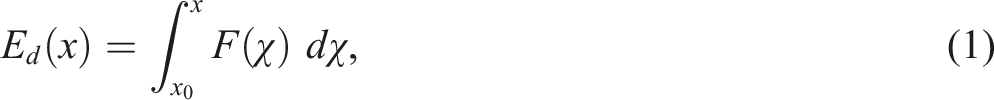
Due to the purpose of the brakes, an efficiency index should account for the energy dissipation capacity E
d
. In general, the energy dissipated through the moving mechanism of a generic brake is:


As detailed data is generally missing, in the present work we investigated four brakes, proposing analytical models which serve to compute ξ. For each technology, the working force trend F(x) is estimated, and an activation force F
a
is defined. This latter represents the force that allows the brake to start working. If F(x) is constant, its value is coincident with
It is worth highlighting that, for every energy dissipating device on the market, the possible combinations of geometries can be potentially countless. Indeed, the geometry is variable both within the energy dissipating device cross-section and for its length. The energy dissipating device length, in particular, can influence the overall flexibility of the barrier. The contribution to the barrier overall flexibility should not be confused with the barrier elongation. The latter is defined in European Assessment Document EAD 340059-00-0106 (EOTA, 2018) as the barrier downslope deformation caused by a rock impact, while the former has now to be defined.
Figure 2 depicts a generic brake (grey box) in its undeformed (a) and deformed (b, c) conditions. Depending on the technology, the brake itself can extend (b) or reduce (c) its length when subjected to external loads. Considering two arbitrary points (i and ii), which are external to the brake and belong respectively to the ground anchor rope (point 1 in Figure 2) and the active rope (2), the distance Δ between them necessarily increases. This increase is called here “contribution to barrier flexibility”, denoted with δ. In other words, δ is the displacement obtained by a tensile test performed on the generic brake, once it is completely deformed. To have a significant comparison among the existing technologies, δ is conventionally fixed to 500 mm in the present work. Since δ depends on the length of the devices, the geometry can vary only within the device cross section. Possible cross section variations enable the realization of a sensitivity analysis to investigate the influence that potential changes in geometry have on the brake performance. Undeformed (a) and deformed (b) (c) conditions.
Working mechanisms of the selected devices
Among the wide variety of technologies in the market, the devices studied in this work were selected among the most common and such to involve different working mechanisms. Pure friction and partial failure technologies were excluded as rarely used in products sold nowadays; as a consequence, three of the selected brakes involve mixed friction/plastic deformation dissipation mechanisms. However, they significantly differ one to the other in how these mechanisms are exerted. Moreover, symmetrical devices are preferred since non-symmetrical technologies tend to increase the number of wire rope terminations, a component which is critical for the barrier durability. The devices analyzed in the present study are shown in Figure 3, along with photographs and explanatory sketches. Photos and sketches of the studied energy dissipating devices. (a-b) double tube (photo source: Gentilini et al., 2013), (c-d) squared tube (photo source: Trad et al., 2013, (e-f) U-brake (photo courtesy of Geobrugg AG), (g-h) brake ring.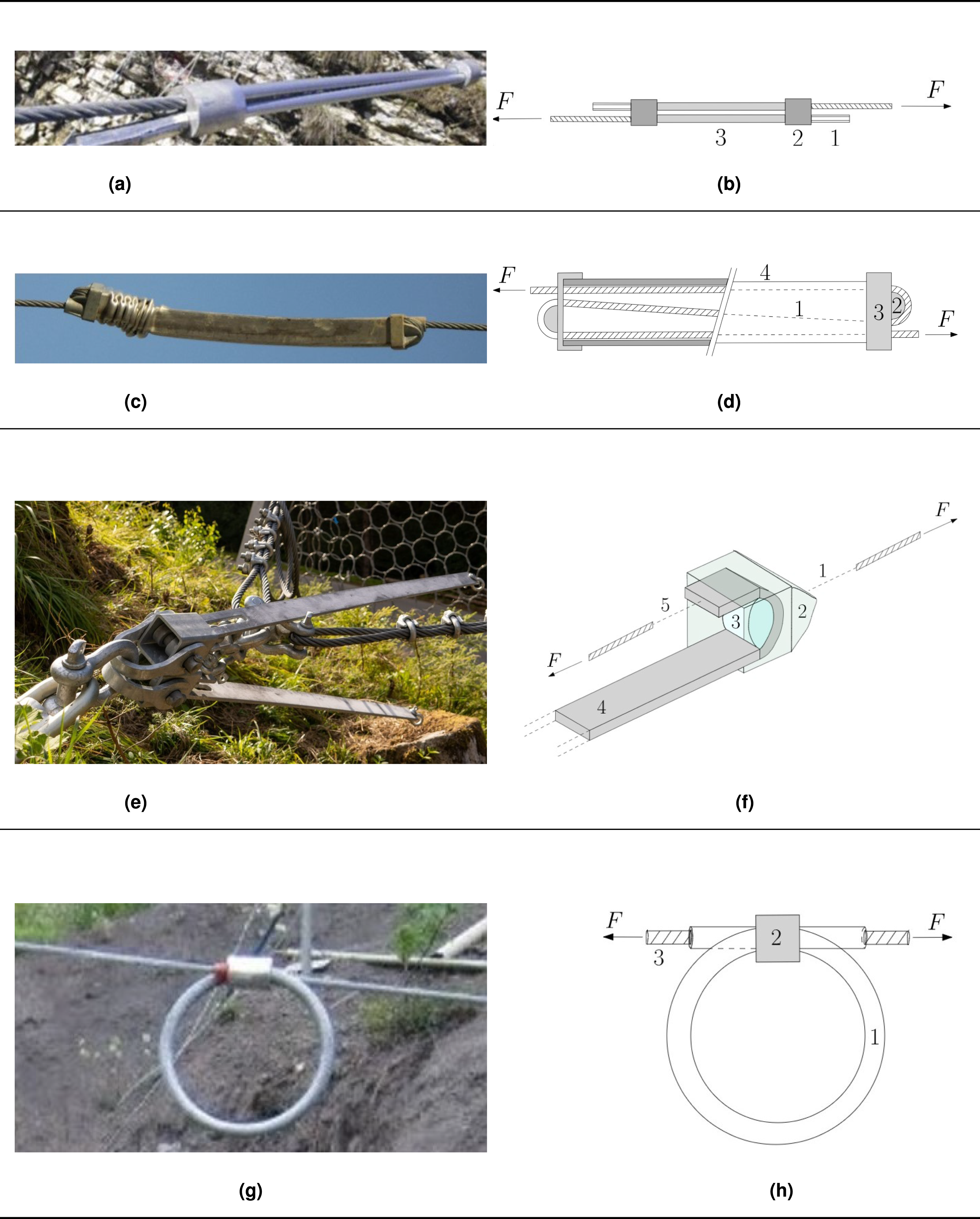
The double tube energy dissipating device (denoted as “brake 1”) is common among existing rockfall barriers as well as in modern installations. It is currently used by the Italian company RISP, but it has been also used by Maccaferri in the past. The compressive load applied to the component induces a distinctive plastic deformation which implies the formation of folds, called shortening buckling. For this brake, shortening buckling is the exclusive source of energy dissipation. As reported in Figure 3(b), two steel ropes are tied with metal fasteners (1), which are restrained at the end by contrast perforated rigid elements (2) connected to two hollow circular tubes (3). During the impact on the net fence, the stressing force inside the ropes increases, resulting in a simultaneous increase in the contact force applied on the steel tubes by the perforated rigid elements and potentially in the shortening buckling occurrence. The compression force applied on the tubes corresponds to the force acting on the steel rope. In general, the mechanical behaviour of a circular tube in a static compression test is characterized by an initial peak, which controls the device activation, and a steady state. In this latter phase, the development of a relevant shortening happens for a force characterized by oscillations around a mean value; oscillations are due to the cyclic formation of folds.
The squared thin-walled tube energy dissipating device (denoted as “brake 2”) working principle is, in some extent, similar to the one of brake 1 but, in addition, friction plays an important role. Its application for rockfall barriers has been proposed in the last decade (Trad et al., 2013) and covers today a limited portion of the market, being used by the French company GTS. As can be seen in Figure 3(d), the wire rope (1) is in this case unique. The rope crosses three times the energy dissipating device sliding along two fixed circular guides (2). These guides are rigidly linked to external constraints (3), which apply compression on the squared thin-walled tube (4).
The U-brake energy dissipating device (denoted as “brake 3”) bases its working principle on plastic deformation and friction. It is the most recent energy dissipator used by the Swiss company Geobrugg and it is widely used in recently installed systems for its quasi-constant behaviour in the force-displacement diagram. In Figure 3(e), two U-brakes are arranged to work in parallel. Analysing the brake from its connection with the anchorage, several elements, represented in the sketch reported in Figure 3(f), can be identified. The brake is linked with the ground anchor rope by means of shackles (1), which connect it to an external case (2), having the role to allocate and fix a steel roller (3). A metallic ribbon (4) is bent over the roller. This ribbon is connected at one end with an active rope by means of clamps (5), while the other end is free. The potential brake travel distance is equal to the distance between the roller and the metallic ribbon free end. Plastic deformation is due to the bending and straightening of the metallic ribbon, while friction dissipation happens for the friction forces which arise at the contact between the sliding ribbon and the external case (due to the ribbon tendency to move outward while sliding) and between the ribbon and the roller.
The brake-ring (denoted as “brake 4”) relies on friction and plastic deformation to dissipate energy. It has been developed by Fatzer AG and it is one of the most common energy dissipating devices in existing high capacity rockfall barriers, that is
Analytical models
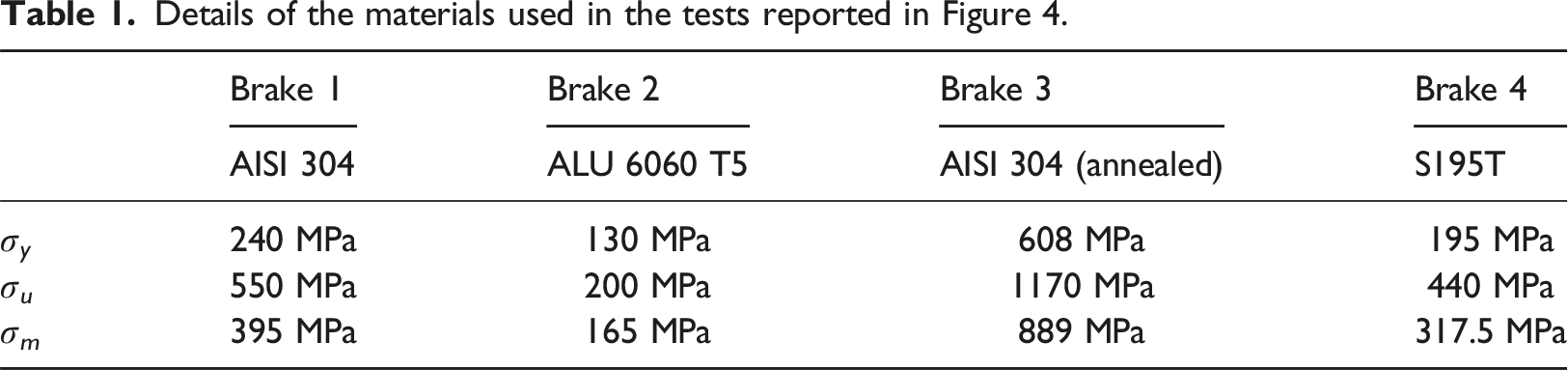
The analytical models for all the brakes analyzed in the present work were developed and validated through the comparison with the available experimental tests. Both the experimental results, found in the literature, and the analytical estimations of the working force F(x) are reported in Figure 4. It is worth noting that for brake 2 (Figure 4(b)) the displacement obtained in the test is 3x, due to the three ropes crossing inside the device. The geometrical properties are reported below each plot, while the mechanical properties of the dissipating component (standard values) are reported in Table 1. Referring to the available experimental results, it is necessary to note that the compliance curves of the brakes are an industrial information belonging to the producers. There is very limited literature reporting the results of tests on such devices. For brake 1, the available data refers to quasi-static tests performed by Wang et al. (2019), also considering different geometrical features of the device. For brake 2, the only published test belongs to Trad et al. (2013). For brake 3, the experimental trend shown in Figure 4(c) derives from averaging multiple tests performed by Min et al. (2016). For brake 4, instead, the experimental test reported in Figure 4(d) is the only one available in literature which is also certainly related to the original device version. In the following years, other tests have been published in literature (Xu et al., 2018, e.g.) on device versions which diverge for the initial one as cross-sectional size is different and, hence, also the confinement pressure (not known) applied by the external compression sleeve could potentially be different. Available data ad analytical models estimation: continuous lines and dash-dotted lines refer to the experimental and analytical trends, respectively, while thin dotted lines represent the mean experimental working force. The thick dash-dotted line is the working force obtained from the analytical models herein developed. (a) Brake 1: Double tube brake, (b) Brake 2: Squared thin-walled tube brake, (c) Brake 3: U-brake, (d) Brake 4: Ring-brake. Details of the materials used in the tests reported in Figure 4.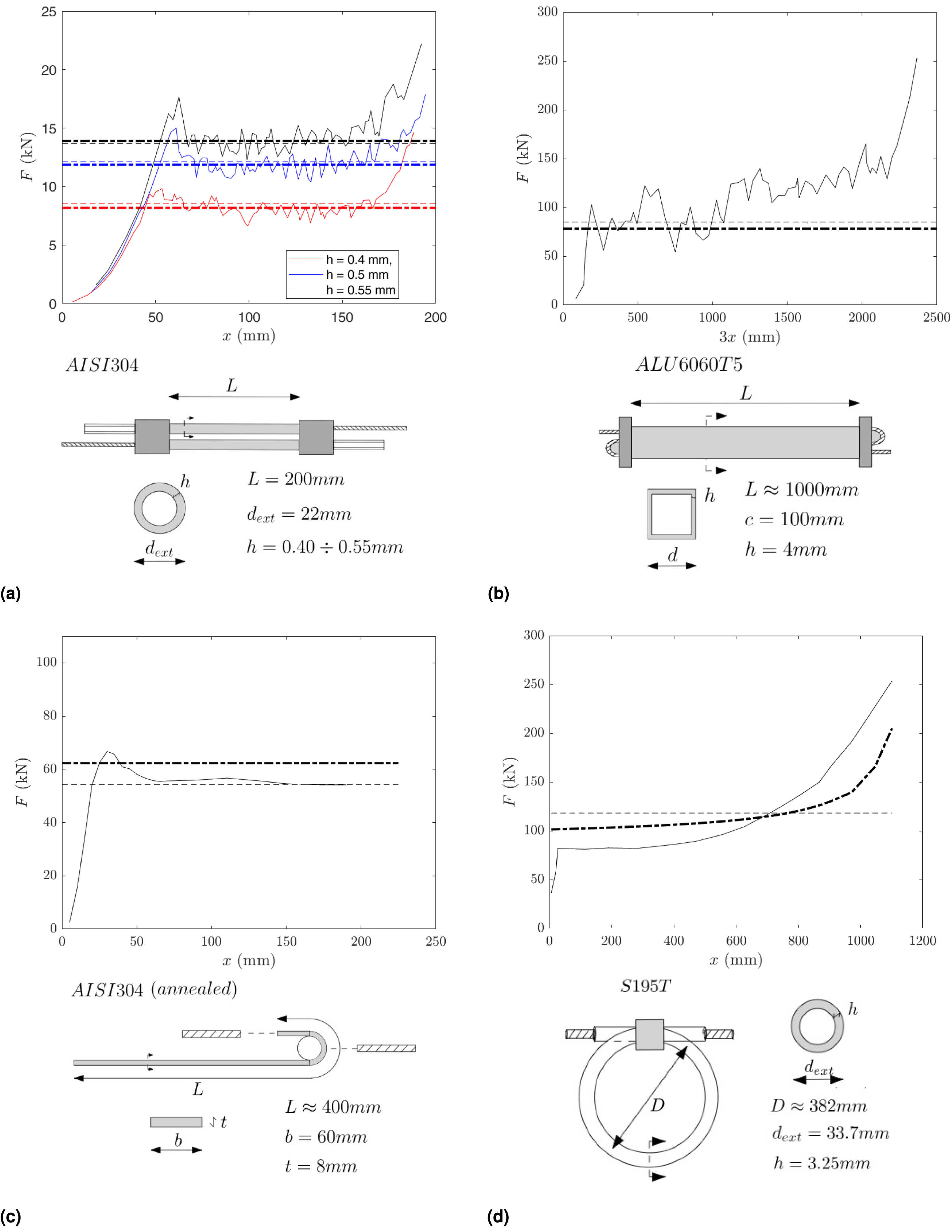
For shortening buckling-based energy dissipators (brakes 1, 2), analytical formulations have been already developed in the scientific literature and were modified and validated in this study. Existing analytical formulations for circular (Guillow et al., 2001; Magee and Thornton, 1978; Singace, 1999) and squared (Abramowicz and Jones, 1984, 1986; Macaulay and Redwood, 1964; Wierzbicki and Abramowicz, 1983) thin-walled tubes are in the form: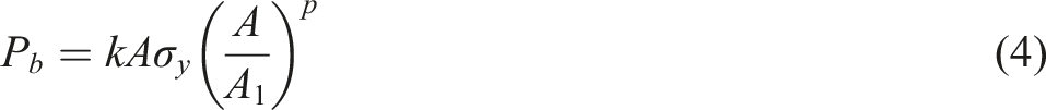
For bending-based technologies (brakes 3, 4), instead, analytical models were built and validated making use of energetic principles. Its application has already been suggested, but not further detailed, by Min et al. (2016) for the brake 3.
Brake 1 - Double tube energy dissipating device
For a generic circular tube subjected to axial compression, different folds formation patterns are possible, depending from the ratios between the tube diameter d ext and its thickness h and between the tube length L and its diameter (Guillow et al., 2001; Lu and Yu, 2003). When the tube is slender, also Euler-type buckling can have an influence on the activation force F a . However, the complete Euler-buckling mode deformation is prevented by the ending restraint applied by perforated rigid elements, and is thus not considered in the present analysis. The deformation mode expected after Euler-type deformation is mixed (Lu and Yu, 2003). The absence of a pure symmetric deformation mode is confirmed by the device post-deformation photographs (Gentilini et al., 2013).
The leading idea was to adapt formulations of to non-symmetric modes (Guillow et al., 2001; Magee and Thornton, 1978; Singace, 1999) to the mixed one. These formulations have the shape of equation (4), with the p coefficient equal to 0.7 and k which is specific of the different formulations. Actually, linking the post-deformation behaviour to the solely σ y would neglect the contribution given by the material hardening, which is believed to be significant since high deformations are induced in the device walls. For this reason, a significant value between σ y and σ u should be used. This choice is compliant with the indications provided in literature (Wierzbicki and Abramowicz, 1983) and was here validated on squared thin-walled tubes, using the results accessible in Langseth and Hopperstad (1996) and computing σ m assuming a linear trend between σ y and σ u in the material stress-strain relationship.
Based on the tests performed by Wang et al. (2019) on a 4-tubes symmetric device, the value of k was determined by the Authors as 2.98. Validation is enhanced by the numerous experiments there reported, in which a range of possible thicknesses is considered. Moreover, also experimental tests on the double-tube crushing device are shown, allowing the model validation for the original version of the device also. In particular, an additional corrective factor k1 = 0.85 is added to take into account of the different applied forces eccentricities between the original and symmetric technologies. Lastly, considering that there are two tubes to be shortened in the brake 1, we have:
The results of equation (5), reported with the thick dashed coloured lines in Figure 4(a) are in agreement with what found experimentally, with a difference of 6% (considering a AISI 304 steel, as from Table 1).
Brake 2 - Squared tube energy dissipating device
For a generic squared tube subjected to axial compression, analytical theories are based on the ideal formation of linear plastic hinges (Wierzbicki and Abramowicz, 1983), also considering that the tube’s walls elongate in specific areas during deformation. This conceptual scheme is reasonable for compact mode collapse only, which occurs for values of the ratio of side to thickness c/h around 20. In the non-compact mode the folds appear to be non-continuous and they are separated by slightly curved panels, while in the compact mode the folds formation pattern is more regular (Lu and Yu, 2003).
Being the literature formulations based on energetic approaches, only the mean shortening force is evaluated, since the initial peak does not significantly contribute to energy dissipation. This concept is due to the quasi-instantaneous nature of the initial peak force and is also valid for circular thin-walled tubes (Section 4.1).
The analytical formula herein adopted (Abramowicz and Jones, 1984) clearly has the same structure of equation (4) and its advantage derives from taking into account the actual crushing distance, which experimentally has shown to be 73% of the total tube length (Abramowicz and Jones, 1984):
Even if a slight hardening phenomenon is present, probably due to stronger friction phenomena for high displacements, F(x) can be considered constant with good approximation.
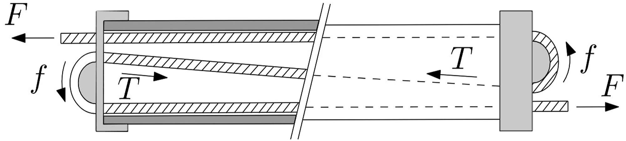
However, differently from brake 1, F(x) and P
b
are not coincident for brake 2, since also friction plays a significant role in the energy dissipation process. As depicted in Figure 5, the compressive force is applied in particular areas at the external plates where the rope cable is guided by circular guides. Denoting with F is the working force, T is the rope stressing force acting between the two circular guides and f is the friction force and μ is the friction coefficient between surfaces, a relationship between F and T can be drawn: Forces acting on brake 2.
The static friction coefficient μ
s
should be used in the non-buckling stage, when the rope does not slide along the fixed circular guide, while the dynamic friction coefficient μ
d
should be adopted in the buckling stage, when the rope slides. Equation (7) denotes that the force loss is not dependent from the guide radius. This means that, in an ideal equilibrium condition, the difference between F and T just depends on the friction coefficient between materials μ, which produces a friction force 
The ratio between P
b
(x) and F(x) ratio is only influenced by the dynamic friction coefficient between the rope and the fixed circular guides. Considering clean metal on metal, the friction coefficient ranges between 0.40 and 0.80 (Blau, 2009). As a result, the buckling force should be from 8.1% to 28.5% higher than the measured force. It is worth highlighting that the friction coefficient estimation is complex and depends on numerous factors. For instance, a lower friction coefficient would be reasonable in case of any superficial treatment (e.g., lubrication) applied to circular guides and rope surfaces. Moreover, also contact pressure has an influence: both low and high contact pressures tend to decrease the friction coefficient for the influence of superficial oxides and local plasticizations respectively. For energy dissipating devices, μ is also strongly influenced by the local conditions, which are related to the specific installation. For this reason, in this work we used conventionally μ
d
equal to 0.5 and μ
s
equal to 0.7 for all the brakes in which friction contributes to energy dissipation. While the latter is adopted for the activation force F
a
estimation, the former is used to estimate the working force F(x), which results:
Inserting equation (6) into (9), the analytical value of the constant F(x) can be estimated, and as a consequence, the dissipated energy. Using equation (2) the total energy dissipation, due to shortening buckling and friction, can be estimated. While the estimation of P b (x) derives from energetic considerations, F(x) was estimated using static considerations.
As shown in Figure 4(b), the application of equation (9) to the original device (considering a ALU 6060 T5 material as from Table 1) yields to a discrepancy in the order of 8%, which can be considered acceptable for our purposes.
Brake 3 - U-brake dissipating device
To the knowledge of the authors, numerical simulations for investigating the mechanical behaviour of U-brakes are not available. In the experimental campaign here used for validation purposes (Min et al., 2016) two brakes have been tested multiple times in a sequential way. In both tests, in the first sliding examination the peak force revealed to be about 15% higher than the mean force in the sliding phase. Min et al. (2016) have explained the difference between the peak force and the stationary force through the friction between the metallic ribbon and the sleeve. In the latest version of the device the ’free’ end of the metallic ribbon is linked at the active rope by means of shackles. Besides that, in the undeformed stage the ribbon cross-sectional area is reduced. Both the updates on the braking device tend to reduce the peak force in the mechanical behaviour. Thus, in this section, the working force F(x) is considered constant. The activation force F a is thus close to the constant value of F(x), being the use in the formulations of the static friction coefficient μ s instead of the dynamic one the only difference. However, the F(x) function, which is representative of the dissipated energy, is not modified due to the instantaneous μ s influence.
Min et al. (2016) have also proposed the application of an analytical model based on work balance:
In Figure 6(a), the external forces acting on the U-brake are schematized. The roller rotation is expected to happen when the force exchanged between the metallic ribbon and the roller overcomes the rolling resistance, which is expressed by a resisting moment M
res
. For the roller rotational equilibrium the friction force f is equal to M
res
/R, where R is the roller radius. As a consequence, the variation of work and the rotational equilibrium around the roller centre are expressed as a function of M
res
, respectively, as: External forces involved in the process (a) and internal work computation (b).

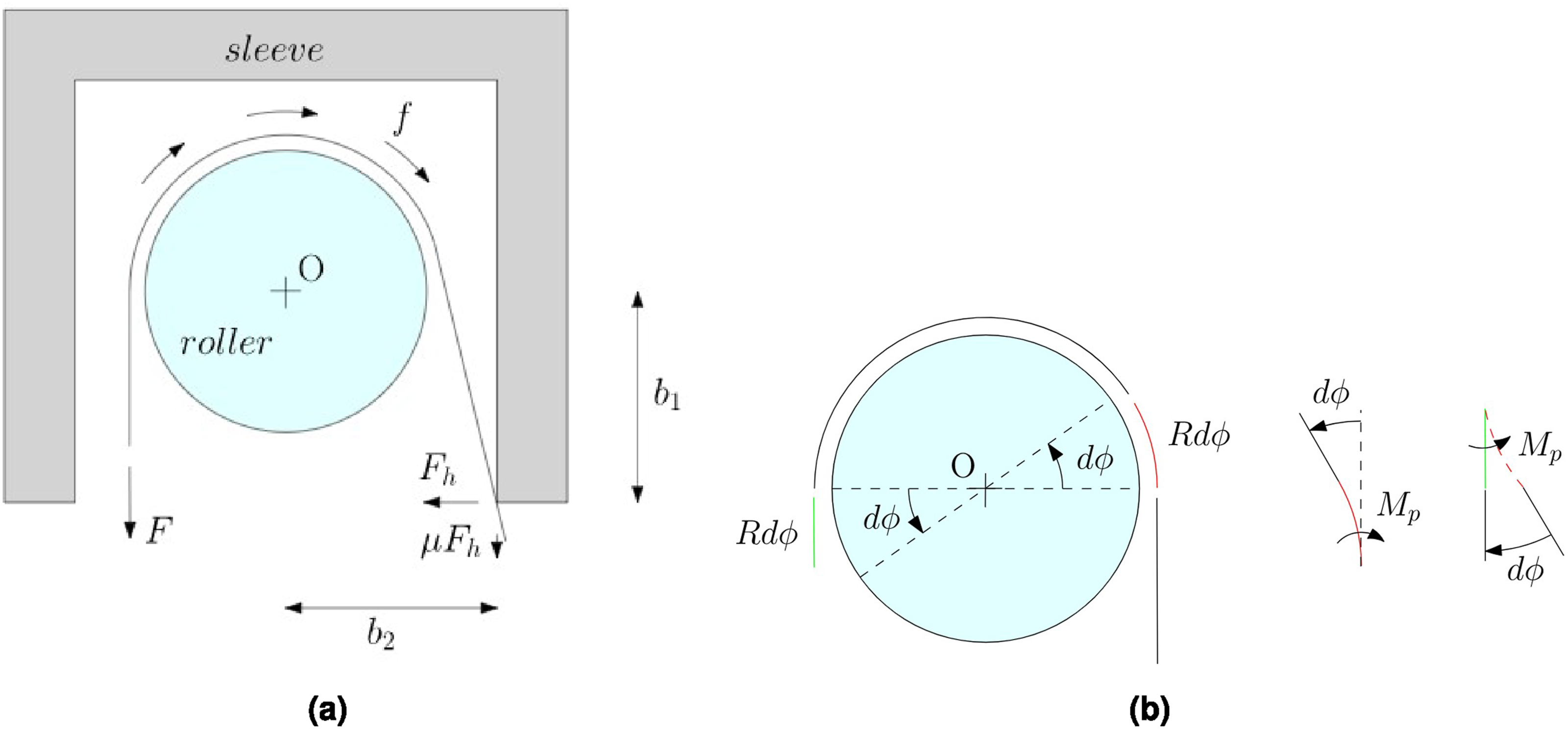
The internal work done inside the metallic ribbon can be computed from the scheme reported in Figure 6(b), which considers an arbitrary infinitesimal movement. Introducing the relationship between the translational movement dx and the rotational movement dϕ, the internal work done in an infinitesimal movement dW can be written as:
Expressing F
h
from equation (12), and introducing equations (12) and (13) into equation (11), it results:
The working force F strongly depends on the geometrical and mechanical properties of the ribbon and on the roller radius. Considering the rolling resisting moment M res as negligible and adopting for μ the choices expressed for brake 2, the expression enclosed in square brackets in equation (14) produces a 10% to 22% increase in force for non-lubricated components (the interval depends on the external case geometry). The average flow stress in the plastic phase σ m was used to compute the plastic moment M p , considering that high deformations are expected on the steel ribbon during the motion. The F(x) computation considering an AISI 304 annealed steel, as from Table 1 leads a 10% deviation from the experimental results, providing an acceptable agreement.
Brake 4 - Brake-ring dissipating device
The analytical model proposed in this paper considers in a separate way the two main contributions to energy dissipation present in the brake-ring. Thus, no interaction is assumed between pure friction and plastic deformation. Regarding the steel pipe plastic deformation, the different conditions at the beginning of the plastic deformation and after its occurring are represented in Figures 7(a) and 7(b). Brake ring in the underformed (a) and deformed (b) condition.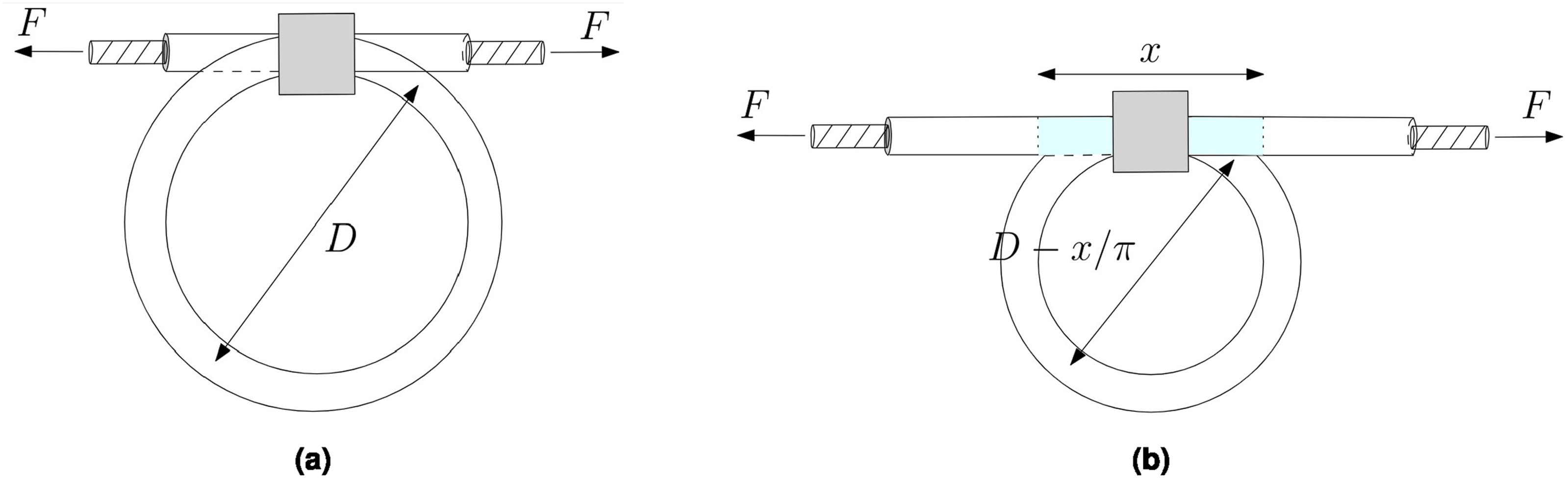
The length of the straightened part corresponds with the total sliding (travel) of the brake, which is denoted with x. The steel pipe’s change in curvature is responsible for the energy dissipated in this mechanism. Specifically, the pipe portions that still belong to the ring have curvatures which are greater than their original one, but for the portions already slid through the aluminium compression sleeve (highlighted in cyan in the Figure 7(b)), the curvature is null. The analytical resolution of the problem is not trivial since the calculation of the bending moment in all sections is required and the moment-curvature behaviour (which is specific for the cross section) should be investigated in detail. In a simplified way, the change in curvature is assumed happening when the plastic moment M p of the sections is reached. As for the brake 3, the mean stress in the hardening phase σ m is used for the plastic moment M p computation.
For simplicity, it is possible to refer to half of the brake since the problem is symmetrical (Figure 8). Simplified sketch of the halved brake-ring.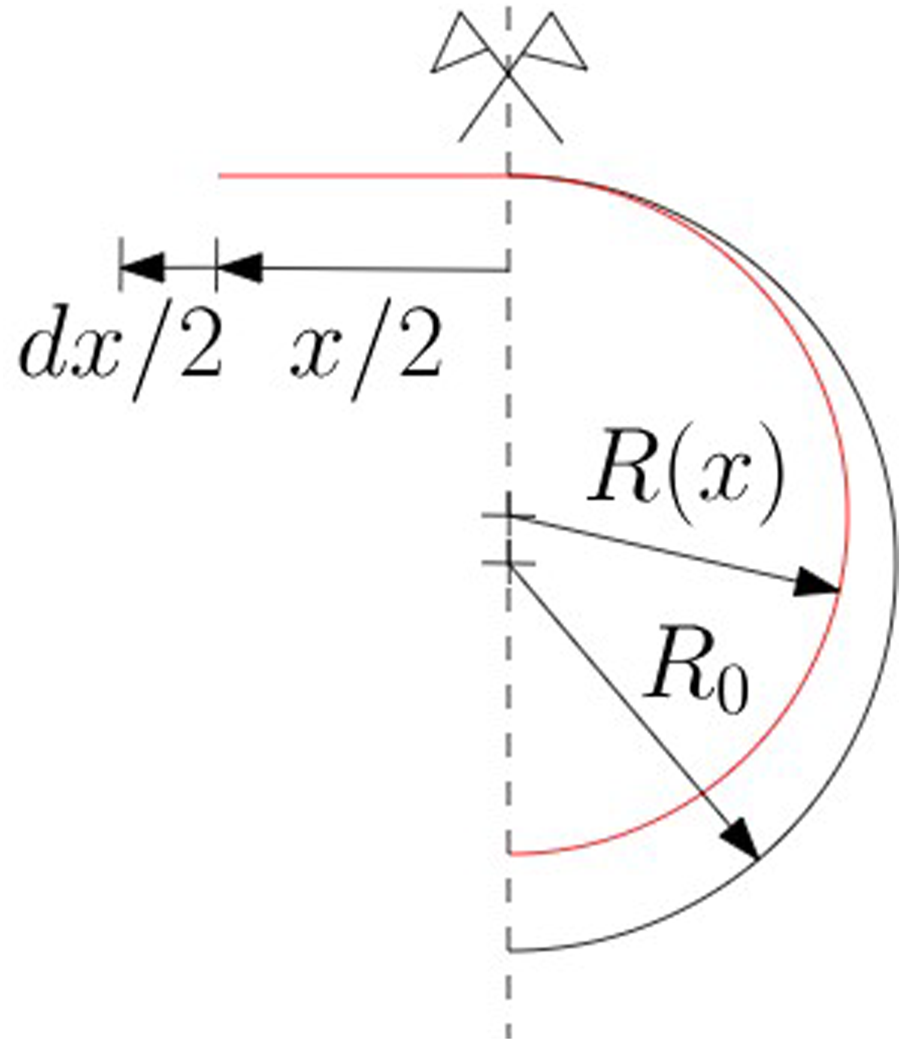
The infinitesimal work performed in straightening and reducing the curvature of half device, neglecting higher order infinitesimals, can be computed as:


An example of calculation is proposed, based on the typical geometry of the device, suggested in the brake-ring patent (Popp and Läpfe, 1994). Results are reported in Figures 9(a) and 9(b) for energy dissipation and working force, respectively. The positive concavity of the total plastic energy dissipation indicates an hardening behaviour. (a) Steel tube plastic energy dissipation calculated with the developed analytical model: E
SD
and E
CD
are the fraction of plastic energy dissipation due to straightening and additional bending, while E
PD
is the total plastic deformation energy dissipation, obtained by summing the former two. (b) Working force: experimental trend (Grassl et al., 2003) (Fexp) and analytical trends due to the sole plastic deformation (F
est,p
) and total (F
est,t
).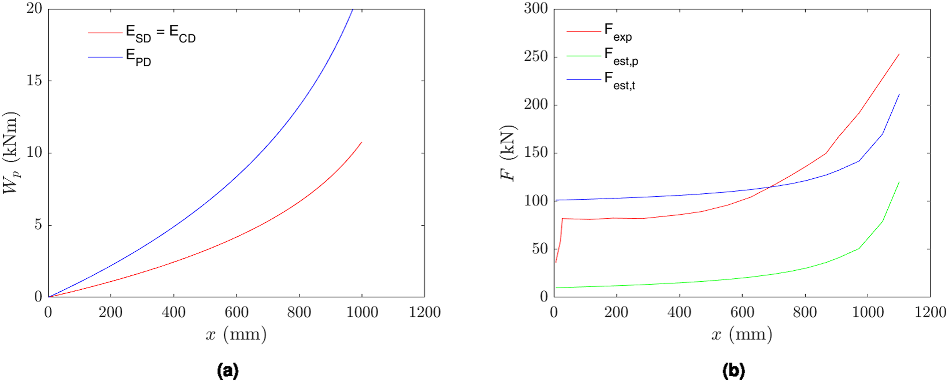
The difference that arises in Figure 9(b) between the experimental F(x) and the obtained F
p
(x) is due to friction, which is indeed the predominant factor in the brake 4 mechanical behaviour. The mean friction force
The work performed by Castro-Fresno et al. (2009) on a similar energy dissipating device can lead to a rough estimation for the confinement pressure applied by the aluminum compression sleeve, which is closely linked to the frictional resisting force. From data extrapolation, indeed, a confinement pressure around 20 MPa is estimated. The confinement pressure applied by the aluminum compression sleeve is considered constant. This means that the friction force f is proportional to the contact surface between the steel pipe and the aluminum compression sleeve. This quantity is, in turn, proportional to the steel pipe external diameter d
ext
. Assuming the compression sleeve length as constant, the friction force can be calculated as:
Due to the hardening behaviour of the brake-ring in the force-displacement diagram (Figure 9(b)), the activation force F
a
and mean working force 


Components efficiency: Results and discussion
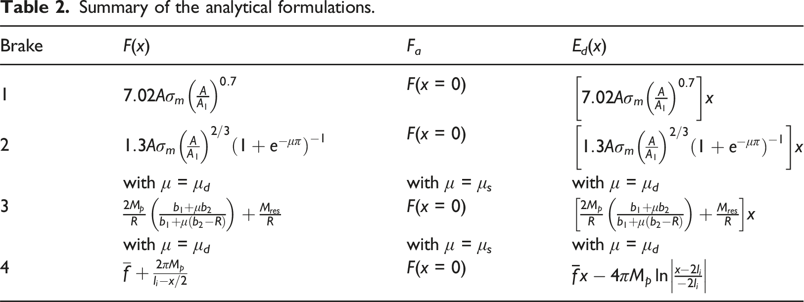
Summary of the analytical formulations.
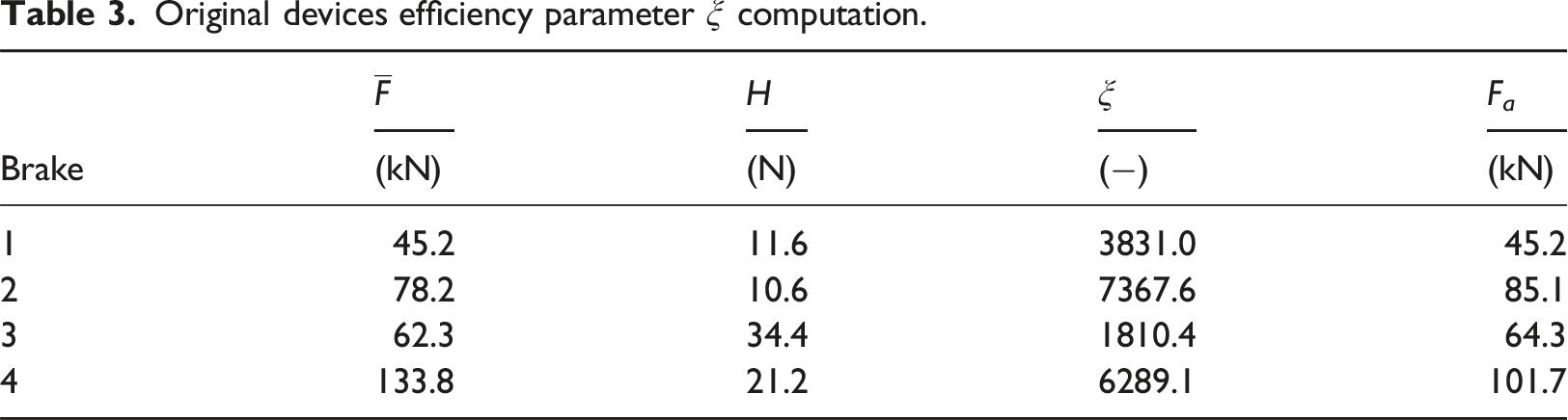
Original devices efficiency parameter ξ computation.
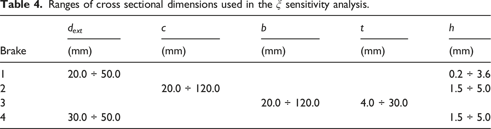
Ranges of cross sectional dimensions used in the ξ sensitivity analysis.
In all the analytical computations, the weight H comprehends the connecting parts. In detail, the external rigid elements needed to apply compression were considered for brakes 1 and 2. The roller and the external case were taken into account for brake 3, while the compression sleeve was considered for brake 4.
As already mentioned in Section 2, for a meaningful comparison between energy dissipating devices, the contribution to the barrier flexibility δ was fixed to 500 mm. This determines the length of each device introduced in the efficiency comparison. As a consequence, L is equal to 700 mm and 230 mm respectively for brakes 1 and 2, since the folds will not assume a null dimension after the complete deformation and considering the three rope crossings inside brake 2; for brake 3, L is equal to 700 mm, while brake 4 has a diameter D equal to 191 mm. Changes in the cross sectional dimensions do not influence δ but impact the index ξ, since both the brake weight H and its mean working force
For brake 1, the sensitivity analysis was performed considering variations in outer diameter d ext and thickness h. As expected, ξ increases with h but decreases with d ext . For brake 2, an increase in h and/or a decrease in c produce an increment in the efficiency index. For brake 3, the efficiency index ξ sensitivity to variations in the ribbon cross section geometry was investigated, finding a reduced ξ sensitivity towards cross sectional geometrical variations. For brake 4, the sensitivity analysis was performed considering possible variations in external diameter d ext and in thickness h. The efficiency parameter ξ tends to increase when d ext and/or h decrease.
The results of the analysis are reported in Figure 10. For each brake, a red dot highlights the ordinary geometry: this represents the efficiency during the brake service life. Efficiency parameter sensitivity analysis (red dot: original geometry).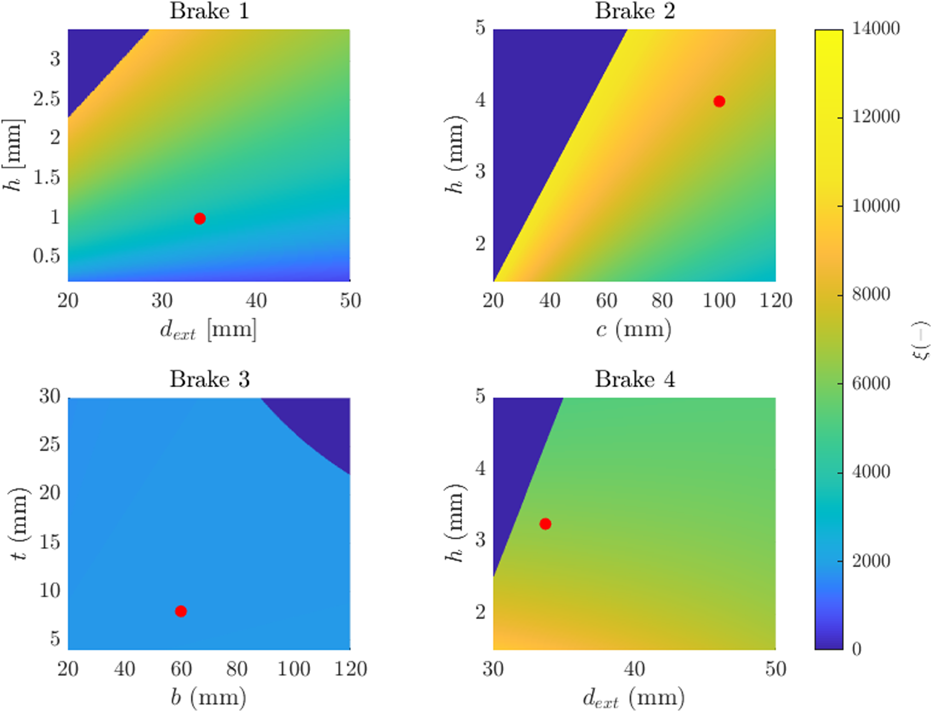
Looking at the results, it is clear that a device realized in aluminium tends to be more efficient than the ones in steel or partially in steel. This is because adopting this material induces a 65% reduction in weight (at constant volume) while mechanical properties are generally comparable.
To overcome the effect of the different materials adopted in the previous calculations, Figure 11 reports the values of the ξ parameter considering the same material in all the four brakes, that is, a S235 steel, adopting its mean mechanical properties (σ
y
= 355 MPa, σ
u
= 435 MPa). Efficiency parameter sensitivity analysis adopting a S235 steel.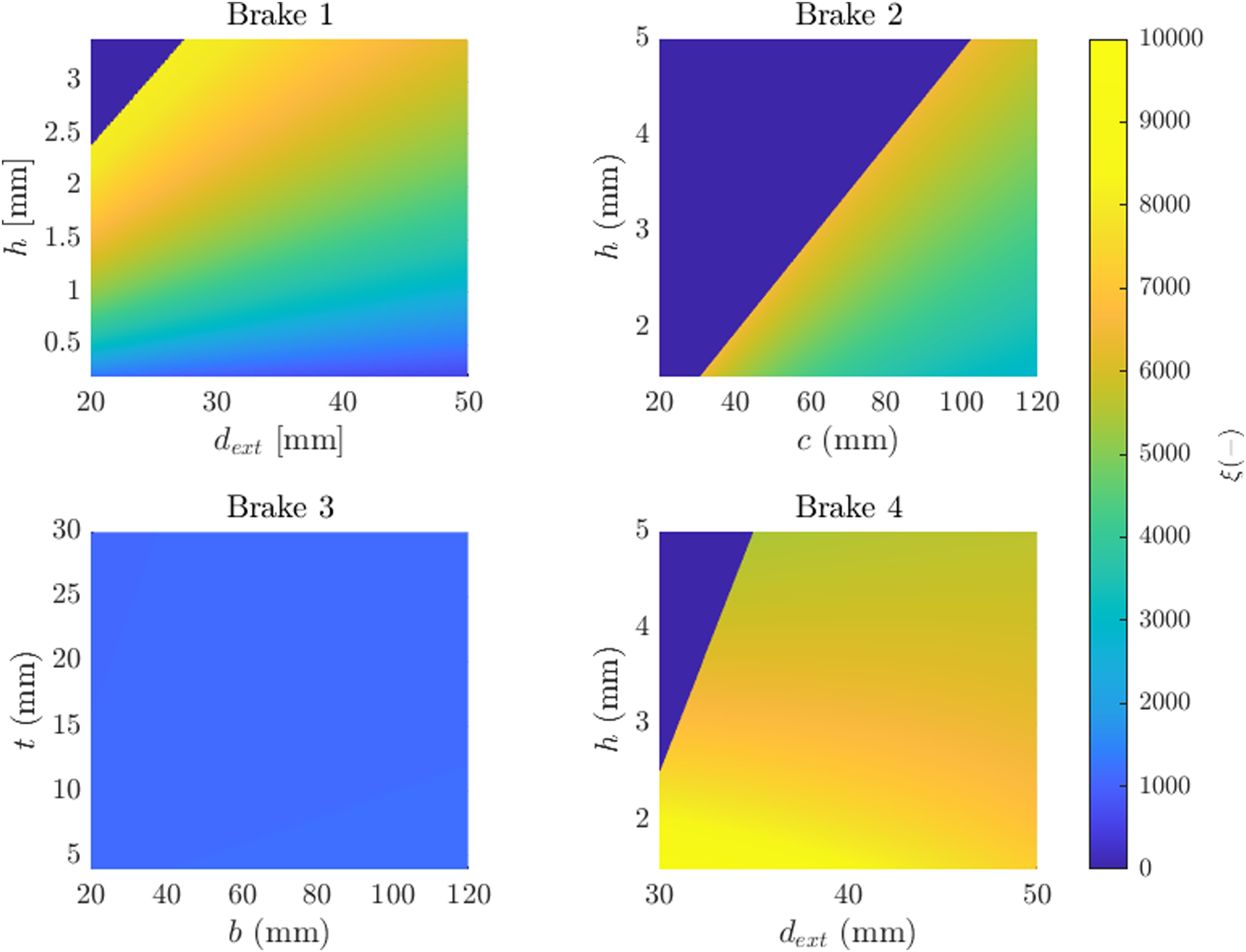
Additional considerations on the influence of the dissipating mechanisms on the trends of the efficiency can be pointed out by comparing Figures 10 and 11. For those brakes which main working principle is based on buckling, that is, brakes 1 and 2, although the diameter (or side length) of the pipe changes the efficiency, the figure is largely affected by its thickness. Basically, this is due to the fact that an increase in thickness implies an increment in the mean working force that is greater than the increase in the pipe’s weight. Going into the details of obtained formulae (Table 2), the crushing force depends on the ratio between the resisting cross-section area A and the area defined by the cross-section perimeter A1. Rearranging the equations related to the dissipated energy of brakes 1 and 2, and including the weight, which is proportional to the cross-sectional area, the efficiency parameter turns to be dependent on the ratio A/A1. This clearly shows that, keeping the external size of the pipe fixed, the efficiency depends on its thickness, as shown in Figure 10. For brake 3, which essentially dissipates the energy thanks to a pure bending mechanism, it is shown that the efficiency is almost constant across the simulated device sizes. This lies in the brake working mechanism and on the fact that
It is worth underlining that the solely ξ is not enough to discuss the suitability of the design. The activation force F
a
coupled with a given efficiency has to be taken into account, too. If this activation force is too high for a certain type of barrier, the brake would not start working and its presence would be useless. If, on the other hand, it is too low, the amount of potentially dissipated energy could be not enough for the design purposes. For each brake, the same efficiency can be reached with various cross-sectional geometries. As already discussed, each cross-sectional geometry implies a related activation force. It is thus possible to obtain a fuse which describes the range of possible activation forces as the efficiency changes for studied energy dissipating devices. The fuses are depicted in Figure 12(a), obtained by applying the analytical models introduced in Section 4 to all feasible cross-sectional geometries within the constraints reported in Table 4, and considering the real fabrication material. Figure 12(b) shows the same information, derived assigning S235 material to all the brakes. A first and general comparison of the plots shows how relevant is the adopted material on value of the efficiency parameter. Brake 4 results also consider scenarios with variation in applied confinement pressure, choosing as upper limit the confinement pressure applied in the real device, and as lower limit a null confinement pressure. Range of activation forces versus efficiency adopting the fabrication material (a) and a S235 steel (b).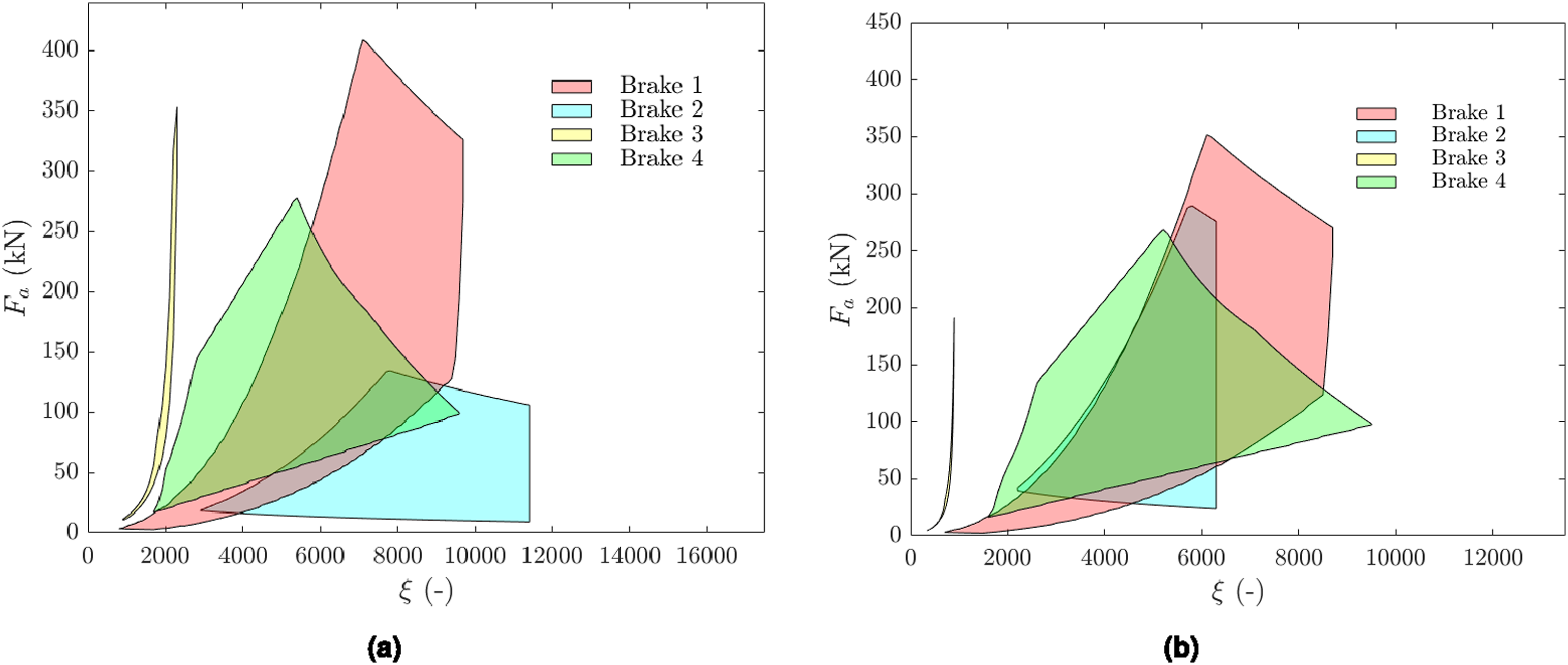
The possible range of activation forces is wide for all the energy dissipating devices introduced in this study. It is immediately possible to notice a similar shape of the fuses. For the buckling-based energy dissipating devices, the maximum activation force always corresponds to largest possible cross-sectional dimensions, which have been set a priori (Table 4). Then, there is a decrease due to the fact that, considering possible reductions in the cross-sectional dimensions, the decrease of quantities
The plots reveal that plastic energy dissipation induced by buckling is, in general, more efficient than the one caused by bending. Looking at Figure 12(b), which enables a comparison between the mechanisms, only, the obtained results for brake 1 and 2 are characterized by a larger fuse in the ξ − F a plane and a relatively high efficiency. The lower boundary is instead related to the smallest cross-sectional size: as a consequence, a large efficiency with a relatively small activation force can be reached for low wire rope diameters only, due to geometrical compatibility concepts. For brake 4, friction has a predominant role in the energy dissipation process, resulting in a high reachable efficiency and a large fuse area, as the friction force does not directly depend on the device weight. However, excluding friction from the computation (a phenomenon related to contact pressures instead than material exploitation), its fuse area would reduce, becoming comparable to the one proper of brake 3.
For bending-based energy dissipating devices, on the other hand, controlling the force-displacement behaviour is easier. In brake 3, for example, varying the cross sectional shape at a certain ribbon curvilinear coordinate means modifying the force-displacement behaviour for a specific displacement value. Hence, the brake force-displacement behaviour can be set a priori, and hardening or softening behaviours can be selected, if they are believed to be beneficial for the barrier working system. Moreover, the limited role that friction plays in the brake’s mechanical behaviour determines a smooth force-displacement behaviour (Figure 4(c)), with very low probability of clogging at a certain displacement during an impact. Another advantage is the geometrical compatibility with all ropes diameter, which is found, among the selected ones, in this brake only. Looking at brake 4, instead, only a hardening behaviour can be set up: anyway, the trend can be precisely controlled by varying confinement pressure, cross size dimensions and length in a combined way.
It is worth highlighting that, in flexible rockfall barriers, brakes are subjected to dynamic loading. Although also advanced numerical papers (Escallón et al., 2014; Zhang et al., 2023) have used quasi-static results to set the mechanical behaviour of energy dissipating devices, it is crucial to discuss the influence that dynamic conditions have on brakes. Results belonging to dynamic tests are reported in Wang et al. (2019) for the symmetrical version of brake 1. Analytically, the yielding stress in dynamic conditions
The analytical formulations presented in this paper refer to the unaltered condition of brakes. In real world, brakes are exposed to atmospheric conditions for decades; hence, their mechanical and geometrical properties can be affected by ageing. Corrosion can influence the working force of the devices by reducing their effective cross section. For devices that dissipate energy mainly through deformation, this aspect generally leads to a decrease in working force and can be approximately modeled by introducing a uniformly corroded thickness. Thus, the brake activation would be in this case facilitated, even if the dissipated energy would be lower. For friction brakes, corrosion can induce clogging phenomena, which imply an additional obstacle to the brake activation, with potentially critical effects on the entire system behaviour.
Beyond this limitation, the efficiency index should be used to compare the different brake technologies, allowing a more significant dissipation mechanism performance evaluation. This information can be used in the Academia, eventually being extended to other civil engineering branches where energy dissipation is essential (earthquake resisting structures, resilient structures), or for industrial aims related to flexible rockfall barriers. If we limit the discussion for this latter application field, the index can be used in the design phase to optimize material and geometrical configuration. Nevertheless, also other features can influence the choice and/or the suitability for a certain system of the generic energy dissipating device, mainly for durability reasons. All the brakes have to be kept in place by connecting elements, whose typology is strictly related to the dissipation mechanism associated to the brake. Their comprehension is fundamental since damage can occur in these parts and some technologies are more prone to degradation if compared with others. This additional specification could orient the brake choice and influence the barrier durability estimation. Connecting components can be absent in devices which are incorporated into the rope cable and control the energy dissipating device mechanism through their shape, but are necessarily present in all the other cases.
For friction brakes, bolted plates represent the most common connection type, but friction can also be introduced by means of compression sleeves that apply compression to the rope itself or to other brake components. When, instead, energy dissipation is done through plastic deformation, mandrels or rollers (usually inserted in appropriate cases) are generally used to establish a guided path for the plastic deformation occurrence. Another option is the introduction of rigid metallic elements, which impede motion by mechanical constraint and cause deformation in the device and in the rigid connectors themselves. Terminations for steel wire ropes (CEN, 2008) are realized applying on the looped wire rope several clips, whose number and size depend on the wire rope diameter and to the chosen termination typology. These connecting elements are common in non-symmetrical devices and should be avoided in highly aggressive environments for ageing vulnerability. When installed, the connection is stable at the wire rope failure load, but after a relatively short ageing period the clips slipping force can become lower. This phenomenon has been observed by the authors during in situ inspections on installed barriers and could impede the brake activation, resulting as a source of divergence between rockfall barriers real and certified mechanical behaviour (EOTA, 2018).
Conclusion
The comprehension of the mechanisms involved in the energy dissipating devices is crucial to determine the overall performance of a flexible rockfall barrier. The presented results confirm the possibility to apply reliable analytical models for common existing technologies. More precise brakes force-displacement behaviours introduced in barriers global analytical models could be used to estimate in an expeditious way the degree of residual safety provided by an installed barrier.
Despite the dynamic nature of the impact can influence the brake mean working force, the development of analytical models has here also enabled a critical comparison between some of the most common energy dissipating devices, through an efficiency index. By referring the energy dissipation capacity to the weight of each brake, an idea about the goodness in exploitation of the material can be achieved.
The results show that, in general, the shortening buckling mechanism is more efficient than the bending mechanism for the purpose of energy dissipation. However, for applications in flexible rockfall barriers other aspects should be considered, that is the possibility to regulate the force-displacement behaviour point by point and the device durability; the ability of a system to maintain unaltered its nominal capacity is strongly influenced by the typology of the applied connecting elements. Lastly, also production costs should be taken into account.
Future developments could encompass the insertion in this framework of other devices and the study of the effects that the dynamic nature of the impact and ageing of the devices have on their working mechanism. This would lead to a wider comprehension of the overall performance of installed barriers, allowing efficient maintenance procedures for rockfall protection systems.
Footnotes
Declaration of conflicting interests
The author(s) declared no potential conflicts of interest with respect to the research, authorship, and/or publication of this article.
Funding
The author(s) disclosed receipt of the following financial support for the research, authorship, and/or publication of this article: This paper was produced while (F.P.) attending the PhD programme in Civil and Environmental Engineering at Politecnico di Torino, cycle XXXVIII, with the support of a scholarship co-financed by the Ministerial Decree no. 352 of 9th April 2022, based on the NRRP - funded by the European Union ‐ NextGenerationEU ‐ Mission 4 “Education and Research”, Component 2 “From Research to Business”, Investment 3.3, and by the company Geobrugg AG.