
Abstract
Soft creatures like Drosophila larvae can quickly ascend tubular surfaces via rolling, a capability not yet replicated by soft robots. Here, we present a single-piece soft robot capable of rolling along tubular structures by sequentially actuating its built-in axial muscles. We reveal that the sequential actuation generates distributed spinning torques along the robot’s curved axis, enabling continuous non-coaxial rolling—distinct from current gravity-dependent rolling solutions. This non-coaxial rolling mechanism allows the robot to swiftly navigate tubular surfaces while conforming to their shapes and maintaining a stable grip. The robot’s deformation and gripping force are actively adjusted to enhance its adaptability to various surfaces. We demonstrate that our robot can ascend pipes with varying geometries (e.g., varying-diameter, spiral-shaped, or non-cylindrical), traverse diverse terrains, pass through confined tunnels, and transition smoothly between planar rolling and pipe climbing. The robot’s great adaptability and rapid movement underscore its potential for navigating scenarios with intricate surface geometries.
Introduction
Soft locomotive robots have emerged as a powerful solution for navigating complex, unstructured environments that are inaccessible to traditional robots, owing to their remarkable flexibility, adaptability, and environmental compatibility. Recent developments have utilized smart materials like fluidic elastomer actuators,1–3 dielectric elastomer actuators,4–6 shape memory polymers,7,8 and magnetic actuators,9,10 enabling soft robots to operate under challenging conditions such as multi-terrain,11,12 confined,13,14 and underwater environments.15,16 Despite these advances, achieving fast and stable locomotion on curved surfaces, particularly those with steep inclines (e.g., vertical or inverted), remains a significant challenge for the soft robotics community.
To tackle this challenge, the key issue lies in generating an active and stable grip on curved surfaces with steep inclines throughout dynamic navigation, which has not been completely addressed by current locomotion mechanisms. Inchworm-like crawling, commonly used by soft robots to explore diverse environments, typically features a body-feet structure. In such a design, the soft body deforms to shift the robot’s center of mass, while two feet alternately adhere to surfaces. However, the necessary gait transitions often lead to mechanical instability and falls on inclined surfaces under the effect of gravity. 17 Moreover, the commonly used adhesion strategies, such as vacuum suction,18–20 electroadhesion,21–23 and magnetic adhesion, 24 are mainly effective on flat surfaces. Although shape-morphing feet have been developed to adapt to curved surfaces, 25 the additional actuators required increase the structural complexity. Expansion units have been employed for anchoring during internal pipe navigation,26–28 which, however, is inapplicable to other scenarios. Alternative approaches, such as soft walking29,30 and jumping31–33 robots, face similar challenges when operating on curved surfaces with steep inclines.
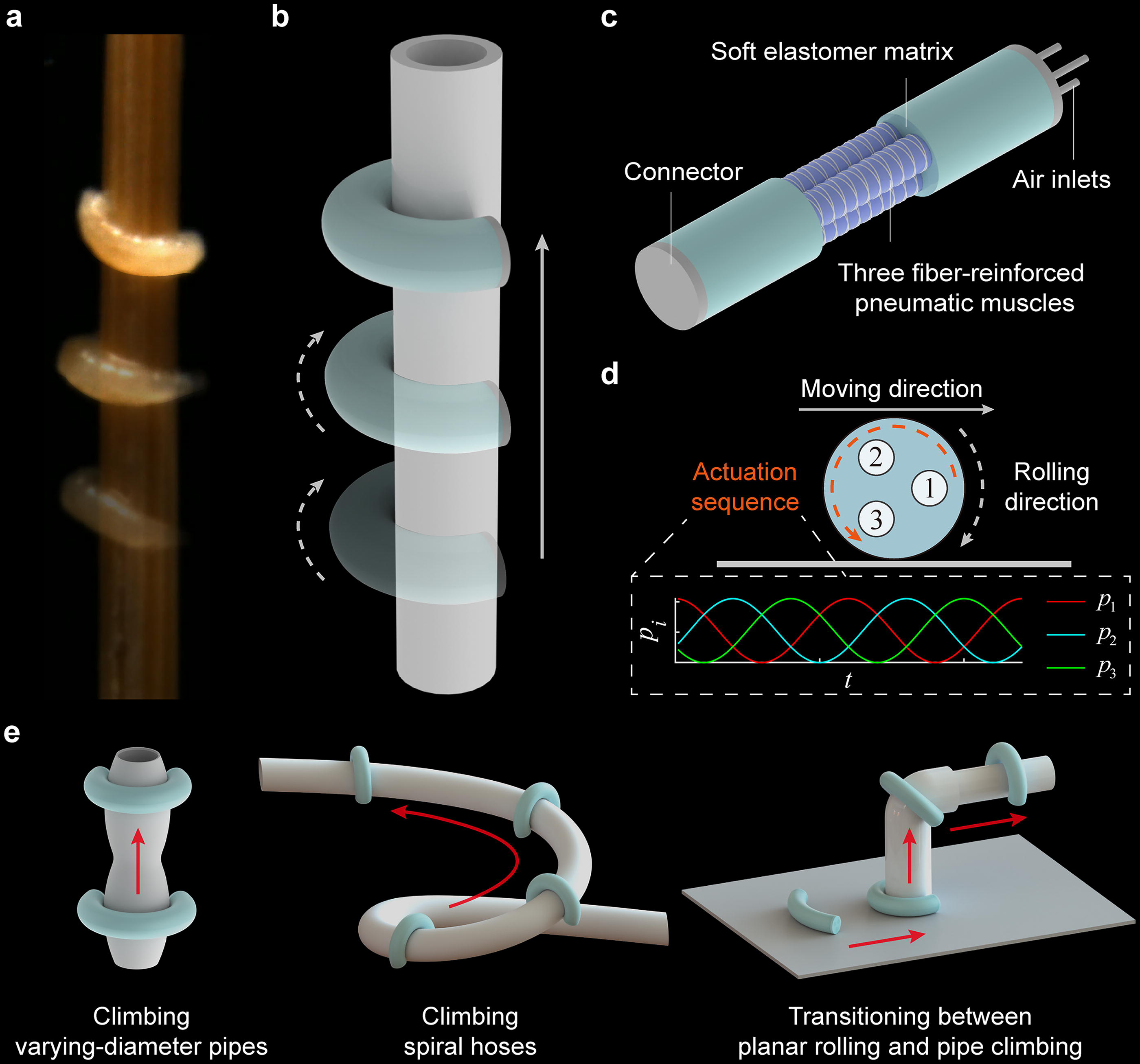
Soft creatures in nature provide inspiring solutions. We observe that Drosophila larvae are capable of ascending a rod via rolling, as shown in Figure 1a and Supplementary Video S1. The larva bends and spins around its own curved axis, maintaining conformity and adhesion to the rod throughout movement. This rolling mechanism enables a stable grip on tubular surfaces to counteract gravity while eliminating the need for gait transitions—a capability that, to the best of our knowledge, has yet to be replicated by soft robots. Although various soft rolling robots have been developed for rapid navigation, most of them generate gravitational torques by deforming their bodies to shift the center of mass,34–38 while others adjust internal forces to redistribute contact forces, producing a rolling moment.39–42 Nevertheless, all these approaches rely heavily on gravity for rolling and fail to generate active surface adhesion, limiting their effectiveness on inclined surfaces. Moreover, most existing designs remain limited to flat terrains, underutilizing the inherent shape adaptability of soft materials for exploring curved surfaces.
Soft tubular-surface rolling robots.
In this work, inspired by Drosophila larvae, we present a soft rolling robot capable of navigating tubular surfaces—a distinct category of curved surfaces (Fig. 1b). The robot features a single-piece structure and exhibits continuous rolling through sequential actuation of its built-in axial pneumatic muscles (Fig. 1c, d). The proposed reduced mechanical model reveals that the sequential actuation generates distributed gravity-independent torques along the robot’s body, enabling continuous spinning around its curved central axis. This non-coaxial rolling mechanism allows the robot to consistently conform to tubular surfaces, without the need for gait transitions, and the maintained bent configuration ensures a stable grip throughout its movement. The robot’s bending curvature and gripping force can be actively adjusted to further enhance its adaptability to tubular surfaces with varying diameters. We demonstrate that our robot achieves upward pipe climbing at speeds up to 22.7 mm/s and planar rolling at speeds up to 119 mm/s, capitalizing on the inherent high efficiency of rolling. Furthermore, the robot is capable of climbing varying-diameter pipes and spiral steel wire hoses, rolling on planar surfaces with different materials and inclines, passing through confined tunnels, and transitioning smoothly between planar rolling and pipe climbing, highlighting its exceptional adaptability to complex environments (Fig. 1e).
Materials and Methods
Design and fabrication
We design a soft rolling robot featuring a single-piece structure. The soft body of the robot comprises three pneumatic muscles, which are uniformly distributed inside a soft elastomer matrix (Fig. 1c). Each pneumatic muscle is fiber-reinforced to inhibit the radial expansion, ensuring that deformation occurs predominantly along the axial direction. The pneumatic muscles are made of Dragon Skin 10 Slow (Smooth-On, USA), which is relatively high-modulus to ensure sufficient mechanical strength, while the elastomer matrix is made of Ecoflex 00–30 (Smooth-On, USA), which is relatively low-modulus to obtain large bending deformation upon actuation. The soft body is bonded to two connectors, one of which provides three air inlets. The robot has an original length of 126 mm and a diameter of 24 mm. The rationale behind the selection of the robot’s dimensions is presented in Supplementary Data S1. The detailed dimensions of the robot are presented in Supplementary Fig. S1.
The fabrication of the robot mainly contains the following six steps (Supplementary Fig. S2). (1) Degassed liquid silicone rubber (Dragon Skin 10 Slow, 1:1) is poured into molds of pneumatic muscles. Cores are inserted into the molds to form the chambers. (2) After 7 h, pneumatic muscles are cured and removed from molds. (3) Polyethylene threads (diameter, 0.2 mm; Yunshangpiao Co. Ltd., China) are wound around the pneumatic muscles. (4) Degassed liquid silicone rubber (Ecoflex 00–30, 1:1) is poured into molds of the soft elastomer matrix. Pneumatic muscles with cores are inserted into the molds. (5) After 4 h, the soft body is cured and removed from molds and cores. (6) Air tubes (outer diameter, 2 mm) are fixed in one of the connectors. The connectors are bonded to both ends of the elastomer body by silicone adhesive (Sil-Poxy, Smooth-On, USA). Both the molds for the soft body and the connectors are designed using SOLIDWORKS and then are 3D printed by a commercial 3D printer (X1-Carbon, Bambu Lab, China). A planetary centrifugal mixer (ARE-310, THINKY, Japan) is utilized for stirring the liquid silicone rubber. A vacuum chamber (VB-1, Changshu Tongrun Electronic Technology Co., Ltd., China) is utilized for degassing the liquid silicone rubber.
Working principle
The robot is capable of bending in multiple directions by modulating the pressurization of its pneumatic muscles. The bending direction is determined by the orientation of the resultant actuation moment generated by the applied pressures. When the pneumatic muscles are sequentially pressurized, the orientation of the actuation moment rotates and leads the robot to alter its bending direction simultaneously. The shift of bending direction results in omnidirectional bending when the robot is fixed at one end, or results in continuous rolling when the robot is freely placed on a surface (Fig. 1d). In the latter case, the robot’s lateral side can adapt well to flat surfaces, while its inner circumference can adapt well to tubular surfaces, so the robot is capable of rolling efficiently across both types of terrains. We develop a kinematic model (see Supplementary Data S2 and Supplementary Fig. S3 for details) that maps the relationship between the robot’s omnidirectional bending and rolling locomotion, offering insight into the robot’s locomotion mechanism.
Specifically, a set of sinusoidal signals is utilized for the actuation of the three pneumatic muscles, which can be mathematically described as
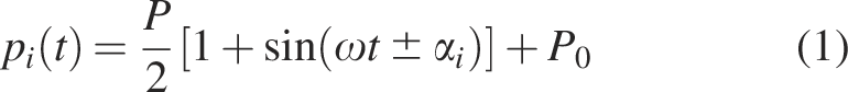
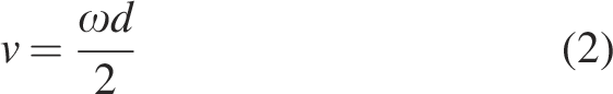
By modeling the elongation and bending of the robot, it can be shown that when the sinusoidal signals are phase-shifted by equal angles of 120°, the robot’s length and bending curvature remain unchanged, while its bending direction changes periodically (see Supplementary Data S3, S4, and Supplementary Fig. S3 for details). This property is crucial for the robot to maintain a stable grip on the tubular surface throughout its movement, as variations in the robot’s bending deformation may break contact with the surface. The robot’s rolling direction is determined by the actuation sequence, which corresponds to the plus–minus sign in Eq. (1). Assuming the robot rolls without slipping, the rolling angular velocity equals ω, and its moving speed v can be expressed as
Theoretical analysis of rolling locomotion
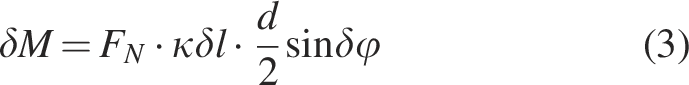
To theoretically elucidate the mechanism underlying the rolling locomotion of the robot, we propose a reduced mechanical model. For simplicity, the robot is conceptualized as a homogeneous elastic beam with multiple axial muscles equidistantly distributed along its circumference. Here, each muscle is represented by a fiber whose length can be actively adjusted, and the sequential actuation strategy translates into the successive activation of these muscles. Initially, the robot maintains a bending configuration at an equilibrium state where the activated muscle lies on the outer circumference of the robot. We assume that the robot undergoes constant-curvature bending with a fixed curvature κ. When the neighboring muscle is activated, the initial equilibrium state is disrupted. At this moment, the newly activated muscle tends to elongate and experiences compressive axial forces FN until reaching the next equilibrium state. For any infinitesimal segment of the robot (δl), these compressive forces FN serve as unbalanced forces, propelling the motion of the segment. We establish a coordinate system O −xyz for the infinitesimal segment, where the xOy plane coincides with the bending plane (the plane where the arc of the robot lies on), and the y − axis is perpendicular to the segment’s central cross-section. As depicted in Figure 2a, the interacting forces at the adjacent cross-sections generate a resultant force (FN ·κδl). Notably, the resultant force is oriented along the x−axis and is non-coplanar with the xOy plane, generating a rolling moment δM about the y−axis, which can be expressed as
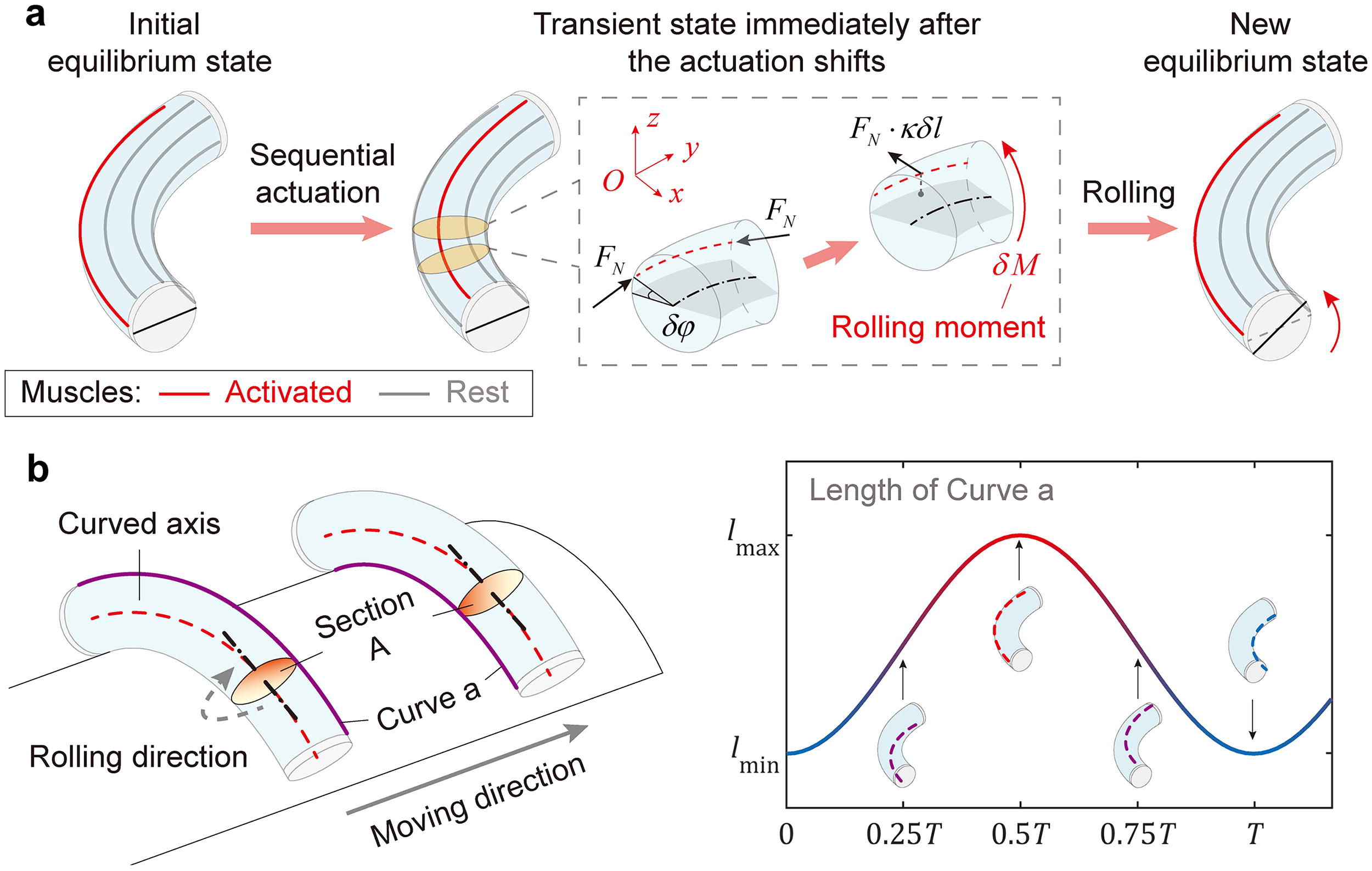
Theoretical analysis of rolling locomotion.
where δφ is the phase shift of actuation. Considering the moment’s distributed nature along the robot’s body length, we further define its density (moment per unit length) as
The robot begins to roll under the rolling moment δM, which is proportional to the compressive force and the bending curvature. Once the muscle reaches the outer circumference of the robot, δM diminishes to zero, and the robot reaches a new equilibrium state. By sequentially activating the muscles, the robot achieves continuous rolling locomotion.
Different from a rigid wheel with a straight rotation axis, the soft robot rolls around its curved central axis in a non-coaxial manner. For any given cross-section (e.g., Section A in Fig. 2b), each material point on Section A rotates about the axis of Section A, which is aligned with the tangent of the curved axis passing through the center of Section A. In the rolling locomotion, each material point on the robot undergoes periodic elongation and contraction variations. To understand this, the robot can be conceptualized as a collection of axial fibers. During one full cycle of rolling locomotion, the length of a fiber reaches its maximum when the fiber is on the outer circumference and reaches its minimum when the fiber is on the inner circumference. The detailed expression of an arbitrary fiber’s length is presented in Supplementary Data S5. The deformability of soft materials allows the robot to rotate about its curved axis, which is unachievable for robots with rigid materials.
Results
Characterization of pipe climbing capability
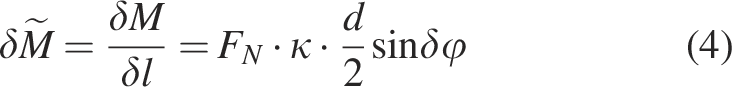
We first evaluate the deformation and force characteristics of the robot. An integrated pneumatic actuation platform is utilized for this work, which mainly comprises a customized pressure regulator (12 channels, Deli Group, China) and an air compressor (OTS-950 × 2, Taizhou Outstanding Industry & Trade Co. Ltd., China). Controlled by a programmable controller (microLabBox 1202, dSPACE, Germany), the integrated pneumatic actuation platform can provide multi-channel desired pressure to the robots (Supplementary Fig. S4). The control signals are generated by MATLAB on a PC and then transferred to the programmable controller via a serial port. In all characterization tests presented in this work, at least three repetitions are performed to ensure the reliability of the results. The deformation characterization results (Supplementary Fig. S5) show that both elongation and bending angle increase with the applied pressure. Thus, for pipe climbing, the pressure amplitude P and the pressure offset P0 in the sinusoidal actuation signals can be modulated to facilitate adaptation to pipes with different diameters. Additionally, it is crucial that the robot maintains a firm grip on the pipe to counteract gravity. To this end, we measure the gripping force of the robot on cylinders with varying diameters (40 mm, 50 mm, and 60 mm). Given the difficulty in measuring the actual distributed gripping forces, we only measure their two orthogonal components in a stationary state, utilizing a home-made device (Supplementary Fig. S6). Two hollow half-cylindrical parts make up the cylindrical gripped object. A single-axis load cell (LSB201, FUTEK, USA) with a compensating linkage is placed in the middle of the two parts to measure the gripping force along the measurement axis. The two orthogonal components of distributed gripping forces are separately measured. The results show that the robot’s gripping force increases with the applied pressure and the pipe diameter (Fig. 3a).
Characterization of pipe climbing capability.
We then characterize the pipe climbing capability of the robot. The robot achieves upward and downward climbing on pipes with varying diameters (40 mm, 50 mm, and 60 mm) via rolling locomotion (Fig. 3b and Supplementary Video S2). We also measure the robot’s climbing speeds on pipes with varying diameters at different actuation frequencies (Fig. 3c). The robot’s climbing speed increases with actuation frequency, basically agreeing with the theoretically predicted rolling speed without slipping from Eq. (2). The downward climbing speed turns out to be slightly higher than the upward climbing speed due to possible slipping caused by gravity, especially when the robot’s grip on the pipe is imperfect. The maximum upward climbing speed is 22.7 mm/s, reached on a pipe with a diameter of 50 mm at an actuation frequency of 0.33 Hz (period, 3 s). The further improvement of climbing speed is limited by the actuation frequency of the pneumatic actuation system. Besides, the robot achieves upward pipe climbing with a payload of 50 g (Fig. 3d and Supplementary Video S3).
Benefiting from the deformability of soft materials, the robot can adapt to pipe diameters within a certain range, but the climbing performance may deteriorate in the cases of thin or thick pipes. For instance, we observe from the experiments that the robot fails to climb pipes with diameters of 40 mm and 60 mm at an actuation frequency of 0.33 Hz. To comprehensively evaluate the robot’s pipe climbing performance, we test the range of available actuation pressures for ascending pipes with varying diameters D (Fig. 3e). A wider range of available actuation pressures indicates greater control redundancy. As expressed in Eq. (1), the actuation pressure can be characterized by the pressure amplitude P, the angular frequency ω, and the pressure offset P0. In this test, the actuation frequency is set at 0.17 Hz (period, 6 s), leading to a constant ω. p1 + p2 + p3 is limited to a maximum of 400 kPa. The pipe diameters range from 35 to 65 mm. The robot used for this test exhibits slight variations in material properties compared to others, which may introduce minor deviations in the actuation pressure. However, these differences do not affect the robot’s overall pipe climbing performance. The actuation pressure is regarded as available if the robot successfully completes at least two out of three trials. A trial is deemed successful if the robot achieves climbing the pipe without obvious slipping while keeping conforming to the pipe during an entire rolling cycle.
The results show that the robot has the widest range of available actuation pressures when climbing a 50 mm diameter pipe. For pipes with smaller diameters (e.g., 40 mm), the robot requires higher P and lower P0 to increase bending curvature and generate sufficient gripping force. However, when P becomes excessively high, the robot bends nearly 360°, causing its ends to touch, which hinders its movement. In the case of a 35 mm diameter pipe, the robot’s achievable bending curvature is smaller than the pipe’s curvature, preventing tight contact. For thick pipes (e.g., 65 mm), the robot requires a higher P0 to extend its body length and improve adaptability. However, due to the maximum pressure limitation, only a narrow range of actuation pressures is available. In such cases, redesigning the robot’s dimensions becomes necessary.
Characterization of planar rolling capability
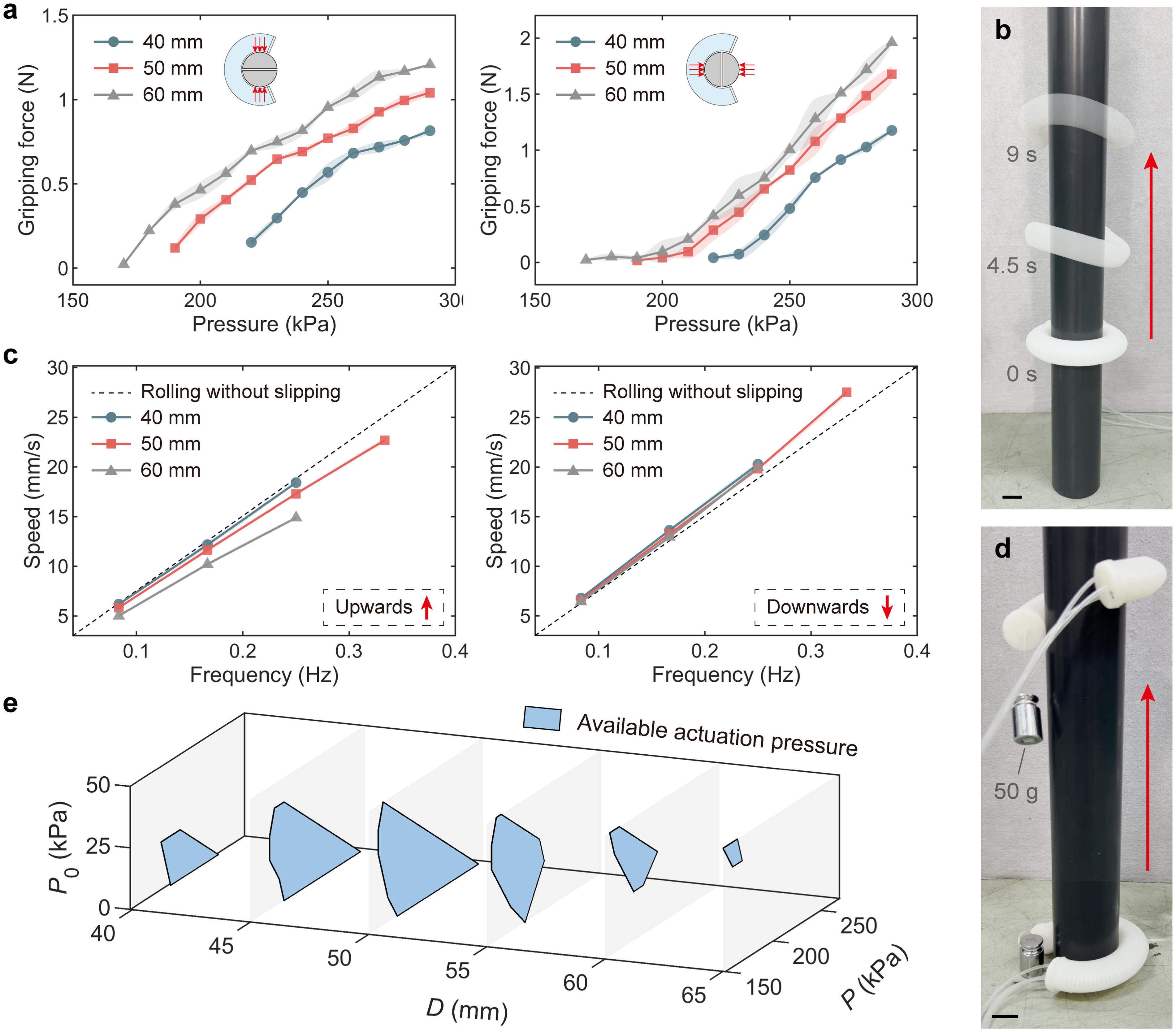
In addition to tubular surfaces, the robot is also capable of rolling on planar surfaces. We demonstrate that the robot achieves rolling outwards (Fig. 4a, top) and inwards (Fig. 4a, bottom) on a horizontal felt board (Supplementary Video S4). As predicted, the rolling direction only depends on the actuation sequence. We measure the robot’s moving speeds with different applied pressures for both outward and inward rolling (Fig. 4b). This test is conducted at a low actuation frequency of 0.17 Hz (period, 6 s) to ensure stable rolling locomotion. Different from rolling on tubular surfaces, the planar rolling directions of different cross-sections are not aligned. The robot’s resultant movement direction is determined by the composition of all its cross-sections. For example, the robot in Figure 4a rolls horizontally because the components of motion in perpendicular directions cancel each other out. In an extreme case, the robot rolls in place when bending nearly 360° (see Supplementary Video S4). This suggests that planar rolling is inherently accompanied by slipping, and the degree of slipping increases with the robot’s bending curvature, resulting in reduced speed. Mechanical analysis also reveals that when the robot rolls outwards, the distributed friction forces from the ground lead to smaller bending curvature, while inward rolling increases the bending curvature (see Supplementary Data S6 and Supplementary Fig. S7 for details). This phenomenon is observed experimentally (see Supplementary Video S4), which also explains the slightly faster speed in outward rolling. We also measure the robot’s outward rolling speeds at different actuation frequencies (Fig. 4c and Supplementary Video S5). This test is only conducted with a low applied pressure (P, 60 kPa), limited by the actuation frequency of the pneumatic actuation system when high pressure is required. Similar to pipe climbing, the robot’s rolling speed increases with the actuation frequency. The maximum speed of planar rolling is 119 mm/s, reached at an actuation frequency of 1.67 Hz (period, 0.6 s), closely aligning with the theoretical prediction from Eq. (2) (125.7 mm/s). The slight speed discrepancy is attributed to inevitable slipping during planar rolling.
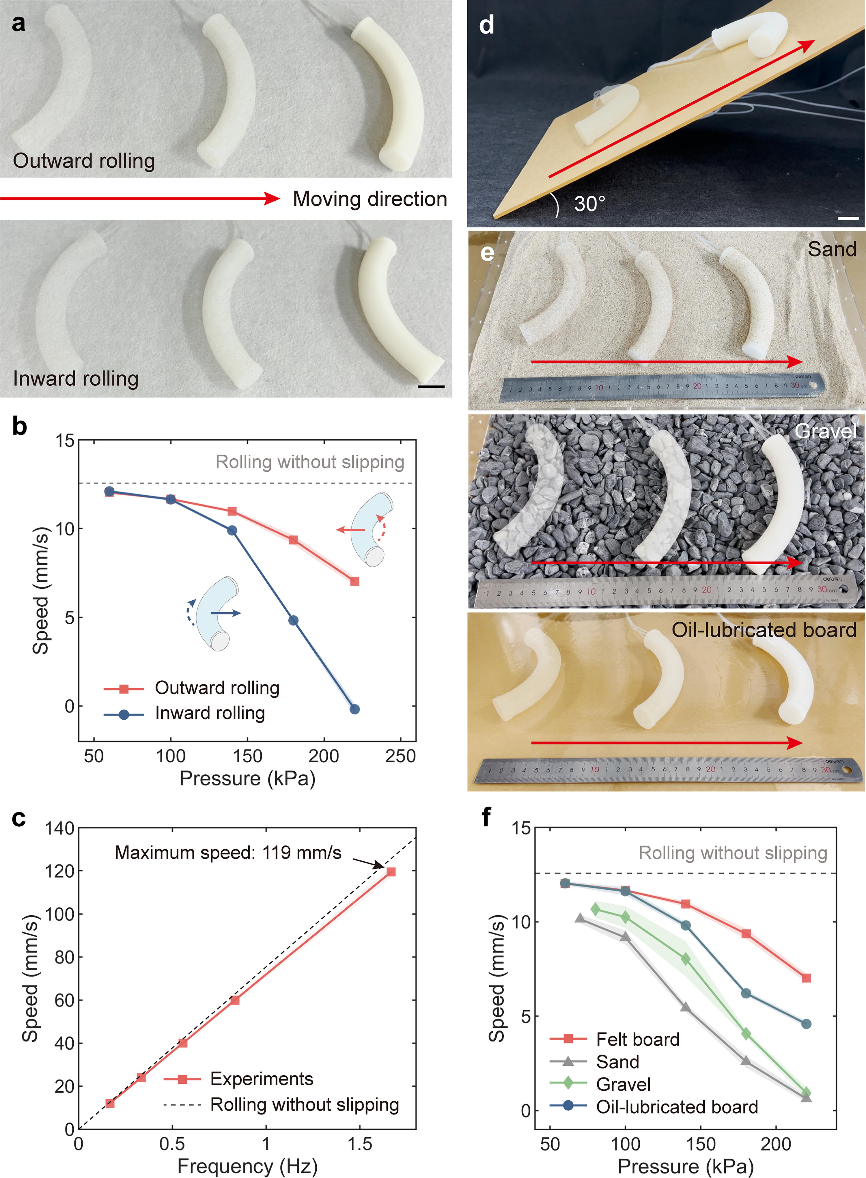
Characterization of planar rolling capability.
We further demonstrate the robot’s ability to roll on surfaces with different inclines and materials (Supplementary Video S6). In Figure 4d, the robot achieves rolling on a flat acrylic board with an angle of 30°. In Figure 4e, the robot achieves rolling on surfaces with varying materials, including sand, gravel, and an oil-lubricated acrylic board, indicating its adaptability to various friction coefficients and contact conditions. We also measure the robot’s outward rolling speeds on these surfaces (Fig. 4f). In this test, five repetitions are conducted to account for the uncertainties introduced by variable terrain conditions (e.g., the distribution of sand and gravel), thereby improving the robustness of the characterization. The dynamic nature of sand and gravel leads to slipping or obstructions for rolling locomotion, resulting in a slower speed. The minimum applied pressure required for rolling on sand and gravel is higher than that on a felt board (P, 70 kPa on sand, 80 kPa on gravel, and 60 kPa on a felt board). This increased pressure is essential to generate sufficient rolling moments to overcome surface resistance. On the oil-lubricated board, despite its low friction coefficient, the robot still achieves effective rolling locomotion.
Adaptability to complex environments
Building on the robot’s fundamental ability to roll on both tubular and planar surfaces, we further showcase the robot’s remarkable adaptability to complex environments. While the robot has demonstrated its capability to climb straight cylindrical pipes, real-world applications often involve pipelines with varying diameters, curvatures, or non-cylindrical shapes. Notably, our robot successfully ascends a pipe with continuously changing diameters (from 40 to 60 to 40 mm; Fig. 5a and Supplementary Video S7). Since the varying-diameter pipe’s geometry is known, the robot’s position and the corresponding local pipe diameter can be estimated at any moment based on Eq. (2), assuming a stable grip is maintained. We select the appropriate actuation pressures for the largest and smallest pipe diameters from the set of available actuation pressures. The actuation pressures for intermediate positions are then obtained via linear interpolation. The employed control strategies are provided in Supplementary Fig. S8. Benefiting from the proposed rolling mechanism, the robot maintains a steady grip while autonomously adapting to the changing diameters. The maximum cone angle of the pipe’s outer surface reaches 46°. Additionally, the robot achieves climbing a spiral steel wire hose by autonomously tracking the curved axis of the pipe (Fig. 5b). Although the spiral pipe may sway as the robot climbs, the robot keeps gripping the pipe, thus preventing it from losing contact or falling. Besides, the robot is capable of climbing non-cylindrical pipes (triangle-shaped and square-shaped; Supplementary Fig. S9), highlighting the effectiveness of rolling locomotion in tubular environments even with limited contact areas. The robot also achieves climbing a horizontal pipe in an inverted posture (Supplementary Fig. S10), showcasing its adaptability to tubular surfaces with steep inclines.
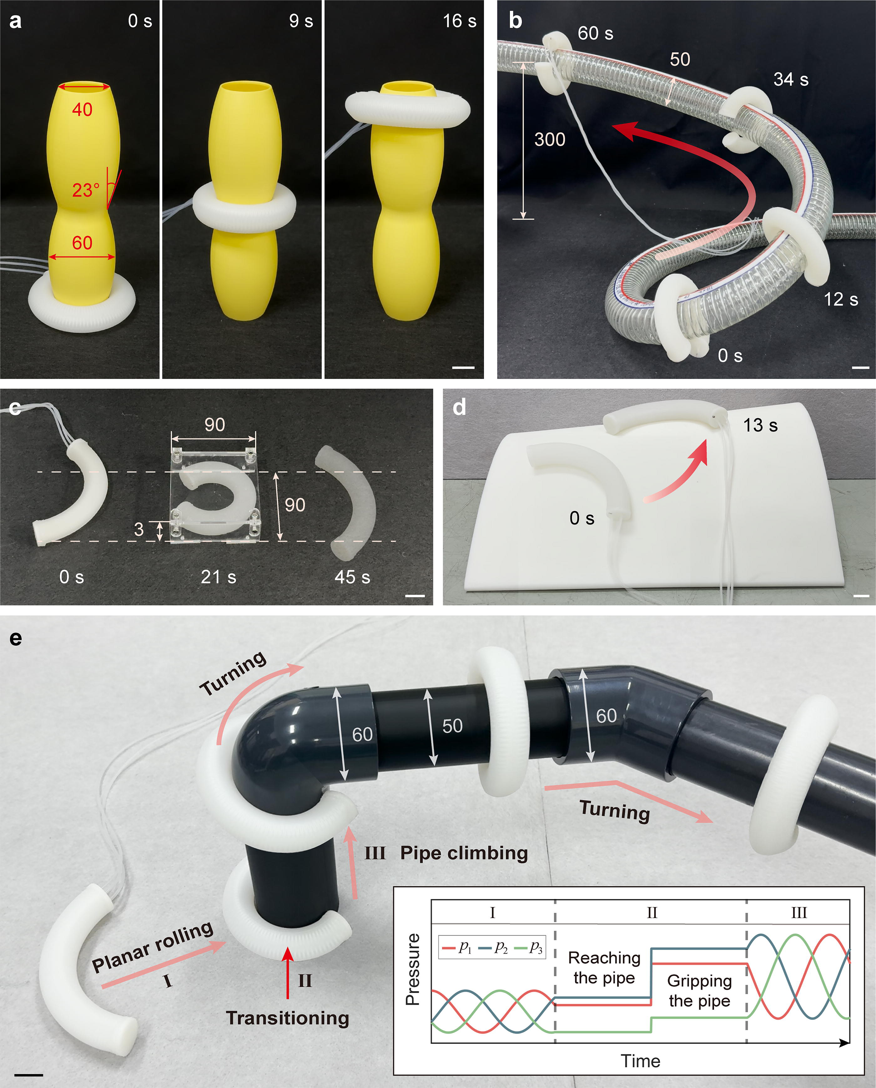
Adaptability to complex environments.
In planar rolling applications, the applied pressure is relatively low to achieve faster locomotion, so the robot is space-saving in height but space-consuming in width. However, when faced with narrow spaces, the robot is also capable of increasing its bending curvature and thus decreasing its body width by applying higher pressures. As shown in Figure 5c and Supplementary Video S8, the robot successfully passes through a confined tunnel with dimensions of 90 mm in length, 90 mm in width, and 3 mm in height. Moreover, the robot’s rolling capability is not only restricted to flat surfaces. In Figure 5d, the robot achieves rolling on a freeform surface with varying curvatures. However, building accurate models for rolling on these complex curved surfaces remains a challenge, necessitating further investigation into contact mechanics.
Finally, we set up a comprehensive experimental environment to further demonstrate the robot’s adaptability to complex environments (Fig. 5e and Supplementary Video S9). The robot begins by rolling on the flat surface towards a pipe. Upon reaching the pipe, the robot halts rolling. The applied pressure increases so that the robot establishes a firm grip on the pipe. Once secure, the robot resumes rolling and ascends the pipe. The employed control strategies are provided in the inset of Figure 5e. When encountering a 90°-bending section, the robot autonomously turns through the bend and continues to roll horizontally. Despite abrupt diameter changes between the straight horizontal pipes (50 mm) and the bending pipes (60 mm), the robot successfully navigates through the pipes. This experiment showcases the robot’s ability to transition between planar rolling and pipe climbing and adaptability to pipes with varying diameters and curvatures.
Discussion and Conclusion
In this work, we present a soft rolling robot for fast locomotion on tubular surfaces with varying geometries. Although many soft robots utilize rolling locomotion due to its agility, they are often limited to movement on planar surfaces without inclinations. Here, we propose a new non-coaxial rolling mechanism by sequentially shifting the bending direction of a soft robot, which exhibits excellent capability to navigate various tubular surfaces, even in cases of inclined or inverted scenarios. Our robot achieves upward pipe climbing at a maximum speed of 22.7 mm/s and successfully climbs pipes with varying diameters, curvatures, and non-cylindrical shapes. Compared with other soft robots capable of climbing tubular surfaces (Supplementary Table S1), our robot exhibits excellent comprehensive performance in terms of both climbing speed and adaptability. Besides, most existing soft robots capable of climbing tubular surfaces feature a body-feet structure and employ two-anchor locomotion. The required gait transitions often lead to instability and even fall. In contrast, our robot features a single-piece structure and employs continuous rolling locomotion via sequential actuation. The continuity of rolling allows the robot to maintain consistent contact with the pipe, reducing the risk of instability or falls during climbing. In addition to climbing tubular surfaces, the robot is also capable of rolling on flat surfaces, at speeds up to 119 mm/s. We further demonstrate that the robot can transition smoothly between planar rolling and pipe climbing, enhancing its versatility in diverse application scenarios. It should be emphasized that the proposed rolling mechanism is applicable to other actuation methods, such as dielectric elastomer actuators and magnetic actuation, in which scenarios the robot is expected to roll faster at higher actuation frequencies.
Despite the promising results, there remain several aspects for improvement. Currently, the pneumatic robot relies on tethered actuation. Although the air tubes for actuation are selected to be long and thin, they still introduce non-negligible drag, particularly during prolonged rolling. Developing an untethered actuation system is critical for enhancing the robot’s mobility for use in practical application scenarios. Additionally, although the robot achieves rolling locomotion in three-dimensional space, its movement is constrained to a single degree of freedom (DoF). As a result, its rolling trajectory depends on the geometry of the contact surface, which cannot be actively controlled. It would be worthy of investigation to increase the system’s DoFs by integrating multiple rolling modules. Developing kinematic models for multi-DoF systems 43 and contact mechanics models 44 will be essential for accurately predicting the robot’s motion in more complex environments. The capability of proprioception and exteroception will also be necessary for the robot’s motion control. In addition, further investigation into the rolling mechanism of soft creatures like Drosophila larvae will provide valuable insights for improving the robot’s design, modeling, and control strategies.
Authors’ Contributions
F.C., Z.Y., and G.G. conceived the idea and designed the study. Z.Y. and K.H. performed the experiments and analyzed the experimental data. Z.Y., F.C., X.H., Z.S., and K.H. developed the theoretical model. Y.D. and Z.G. provided photographs and videos of Drosophila larvae. G.G. and F.C. supervised the project. Z.Y., F.C., and G.G. prepared the article. All the authors provide feedback and agree with the final version of the article.
Footnotes
Acknowledgment
The authors thank X. Yang for his suggestions on experimental design and setup.
Author Disclosure Statement
No competing financial interests exist.
Funding Information
This work was supported in part by the National Natural Science Foundation of China under Grant T2293725 and Grant 52025057, in part by the National Key Research and Development Program of China under Grant 2023YFB4706500, and in part by the State Key Laboratory of Mechanical System and Vibration under Grant MSVZD202401.
Supplemental Material
Supplemental Material
Supplemental Material
Supplemental Material
Supplemental Material
Supplemental Material
Supplemental Material
Supplemental Material
Supplemental Material
Supplemental Material
References
Supplementary Material
Please find the following supplemental material available below.
For Open Access articles published under a Creative Commons License, all supplemental material carries the same license as the article it is associated with.
For non-Open Access articles published, all supplemental material carries a non-exclusive license, and permission requests for re-use of supplemental material or any part of supplemental material shall be sent directly to the copyright owner as specified in the copyright notice associated with the article.