
Abstract
It is challenging to simultaneously estimate the shape and contact force of miniature continuum surgical robots due to the limited sensing capabilities, deformable structure, and complexity of the external environment they operate in. In this work, the integration of a quaternion-based multicontact Cosserat model with contact force regularization enables a dual-pronged approach for simultaneous shape and body contact force estimation using minimum shape measurement input (i.e., tip position). In addition to internal actuation, cable friction, and material nonlinearity, the proposed state estimation approach also accounts for multiple environmental contacts with clinically relevant mixed geometric constraints (point, plane, and curved surface), as these complex and variable anatomical interactions critically influence the robot’s behavior. The solving procedure is then reformulated as a nonlinear large-scale optimization problem to improve the state estimation robustness. Finally, both simulations and experiments on a cable-driven variable-stiffness notched-tube continuum robot were conducted to validate the proposed state estimation approach, demonstrating a comparable level of accuracy to state-of-the-art methods.
Introduction
The work in this article is based on Chapter 2 of Jibiao Chen’s PhD thesis, 1 with Experiment 1 presenting more polished and refined results.
Accurate estimation2,3 of robot states (e.g., robot pose, strain, shape, and contact force) is a fundamental prerequisite for continuum robots to effectively address challenges in design optimization, 4 motion planning, 5 and force control. 6 In general, sensor-based techniques, 7 including embedded sensors and external imaging, are common approaches to measure the robot states for continuum robots. However, continuum robots, especially in surgical applications, often face limited sensing capabilities due to their miniature size, soft deformable body structure, and the complexity of the surrounding environments, 8 which hinder the integration of traditional sensors. 9 Therefore, accurate modeling becomes indispensable, potentially providing a reliable and efficient way for estimating the continuum robot states to ensure its safe operation. 3
Related work
Much modeling effort in the past decade has focused on estimating the robot shape and/or tip force for continuum robots. Lilge et al. 2 recently proposed a stochastic approach that uses Gaussian process (GP) regression for estimating shapes and strains of continuum robots. This approach demonstrates accurate estimation of robot states using a zero-mean prior. Besides, the anisotropic shape for a multi-contact-aided continuum robot was also estimated for endoluminal intervention. 10 The early work by Xu and Simaan 11 presented the intrinsic tip force sensing method based on the singular value decomposition of Jacobian mapping. Back et al. 12 used a classical Cosserat rod model to estimate tip force, leveraging the pre-detected robot shape from an endoscopic camera. Additionally, the robot shape and tip force of laser-profiled continuum manipulators were simultaneously estimated in endobronchial intervention. 13 However, most of these aforementioned works focus on estimation approaches for continuum robots operating in free space or under an external force applied only to the tip of continuum robots.
The motion behavior of continuum robots can easily lead to contact with the surrounding along the arc length of its body, especially in a constrained environment. Therefore, some recent research has focused on sensing body contact force for continuum robots, which presents a more challenging estimation problem than tip force estimation. Ryu et al.14,15 introduced the Cosserat rod model to estimate body contact force, but it requires its body shape as prerequisite information. Based on the fixed centrode deviation method, Chen et al. 16 proposed a two-dimensional model-based approach to estimate the external contact location for a pneumatic soft robot with one degree of freedom (DOF), while neglecting the actual magnitude of the contact force. Cosserat model was then investigated in multiple works for estimation and localization of body contact force for various soft and continuum robots.17,18 Gao and Lin 9 proposed a model-based estimation method utilizing Fiber Bragg Grating (FBG) sensors to measure tendon tension and robot curvature, enabling simultaneous estimation of body contact force, contact number, and contact location. However, most of the aforementioned approaches require prior determination of either the FBG-based robot shape,9,19 both the image-based robot shape and point contact locations,12,18 or image-based contact locations together with environmental constraints 14 as inputs for contact force estimation. This strategy treats shape estimation and force estimation as separate processes without accounting for their inherent nonlinear coupling. 3
Only a few works have been developed to date for the simultaneous estimation of the shape and body contact forces in continuum robots. The pseudo rigid body model20,21 was first proposed to estimate robot shape and body contact force using known contact positions and locations under point constraints. Implementing Lagrange multipliers, an optimization-based framework was proposed to predict profile and body contact force of a planar cable-driven continuum robot in the reference. 22 Ferguson et al. 3 extended the stochastic GP-based approach 2 to enable the estimation of both the robot shape and external force for continuum robots. This advanced approach incorporates the fusion of noise and sensing measurements to enhance accuracy. Toshimitsu et al. 23 employed embedded soft-robot sensors (e.g., internal capacitive flex sensors) to estimate the pose and external forces of a soft continuum manipulator, demonstrating strong potential for proprioceptive sensing. In combination with the finite element method, multitapped flex sensors were further integrated into soft robots by the same group to achieve high-accuracy shape and force estimation. 24 Additionally, a new shooting-based Cosserat rod model 25 and a novel dynamic model with frictional contact constraints 26 were, respectively, presented for modeling soft robots in contact scenarios. By integrating FBG sensors, a model-based approach was proposed to predict shape and body contact force for flexible tubes 19 without considering internal actuation. Lu et al. 27 proposed a data-driven approach to simultaneously estimate the robot shape and contact force through sparse FBG measurements. However, those approaches still necessitate multiple sensor measurements (e.g., several strains, curvatures, and backbone positions) along the robot arc length for the simultaneous estimation. Additionally, many recent works fail to consider internal actuation19,26 and only consider either the point contact constraint3,18,19,28 or the single contact scenarios,18,22 which do not provide accurate representation of most surgical environments.
Contributions
In confined environments, the sensing limitations (e.g., miniature size) of continuum robots allow only minimal shape measurements for state estimation. Incorporating complex mixed external geometric constraints is also crucial for accurately representing realistic environmental interactions (e.g., endovascular navigation), as these constraints significantly affect the robot’s mechanical behavior. In contrast to previous works that employ the model-based approach for estimating robot states under either point loads,3,18,19,28 single contact scenarios,18,22 or situations without internal actuation,19,26 we propose a quaternion-based multicontact Cosserat model for state estimation with minimum shape measurement input, offering robust parameterization and integration of coupled states for continuum robots.
The main contributions of this article can be summarized as follows:
A quaternion-based Cosserat rod model is introduced to perform simultaneous estimation of robot shape and body contact force (both magnitude and location) in cable-driven continuum robots while requiring only the tip position information.
It is a deterministic model-based estimation approach that reduces essential predetermined parameters required in continuum robot state estimation, thereby enabling accurate state reconstruction in constrained environments with minimal shape sensing. The proposed state estimation is reformulated as a nonlinear global optimization problem, employing a large-scale optimization method combined with contact force regularization to enhance the robustness of body contact force estimation. Implemented on a cable-driven variable-stiffness notched-tube continuum robot (VSNC), the proposed approach achieves mean shape error of around 1 mm, mean contact force magnitude error of around 55 mN, and mean contact location error of around 1.5 mm, which are of comparable accuracy to the state-of-the-art (SOTA) methods3,18,19,28 that require additional shape inputs. The proposed state estimation approach takes into account the effects of internal actuation, cable friction, material nonlinearity, and in particular multiple external contacts with mixed geometric constraints, including point, plane, and curved surface constraints that more closely represent the environmental contacts during the surgical procedure. Our approach advances recent works by modeling both the robot’s inherent nonlinearities and the coupling of multiple external geometric constraints, yielding more accurate shape and force estimates.
The rest of this article is organized as follows. The second section formulates the robot state estimation problem for continuum robots, specifically for the VSNC. The third section proposes a quaternion-based multicontact Cosserat rod model for continuum robots. The solving procedure of the proposed state estimation approach is then clarified in the fourth section. The fifth and sixth sections, respectively, evaluate and validate the simulation and experimental results of the proposed Cosserat-based contact estimation approach. The last two sections provide discussion, concluding remarks, and an outline of future work for our article.
Motivation and Robot Structure
Motivation
Implementing robust state estimation methodologies is essential for continuum robots to ensure safe navigation and manipulation, especially in complex surgical environments with the limited shape sensing capabilities. For example, in the endovascular interventional (EI) procedure, navigating catheters and guidewires through the human vascular system is challenging due to the complex mixed external constraints, such as the intricate shape of the vessels like the internal carotid arteries in the neck,29,30 as shown in Figure 1. The limited shape sensing capabilities and the complex external geometry of anatomical structures in continuum surgical robots during the EI procedure motivate our work of quaternion-based multicontact Cosserat modeling for simultaneous estimation of shape and body contact force, using minimal shape measurements and incorporating mixed external constraints. Our motivation is driven by the following two key considerations:
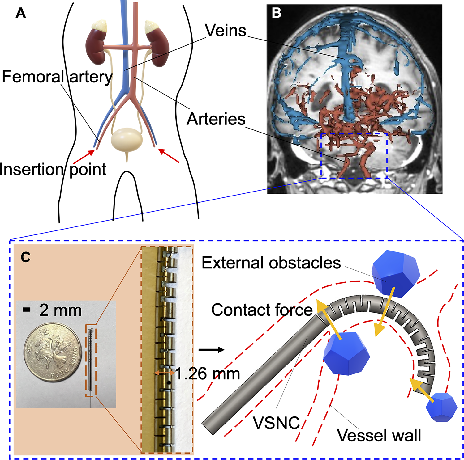
Description of robotic catheterization for the EI procedure.
From a theoretical standpoint, inferring external forces from shape deformation is sometimes ill-conditioned, as similar shapes can result from different force conditions. 28 To address this, we use a high-fidelity Cosserat rod model that jointly estimates shape and force. By representing both pose and contact locations within a modified quaternion-based Cosserat model, we avoid Euler-angle singularities31,32 and achieve robust handling of contacts and boundary forces in multicontact scenarios.
From an application perspective, enabling contact force estimation using only tip position can significantly reduce system cost. Achieving high-resolution shape sensing along the entire body of a miniature continuum robot requires complex and expensive sensor integration, along with sophisticated data fusion. Our method offers the potential to enable contact force estimation using only tip sensing.
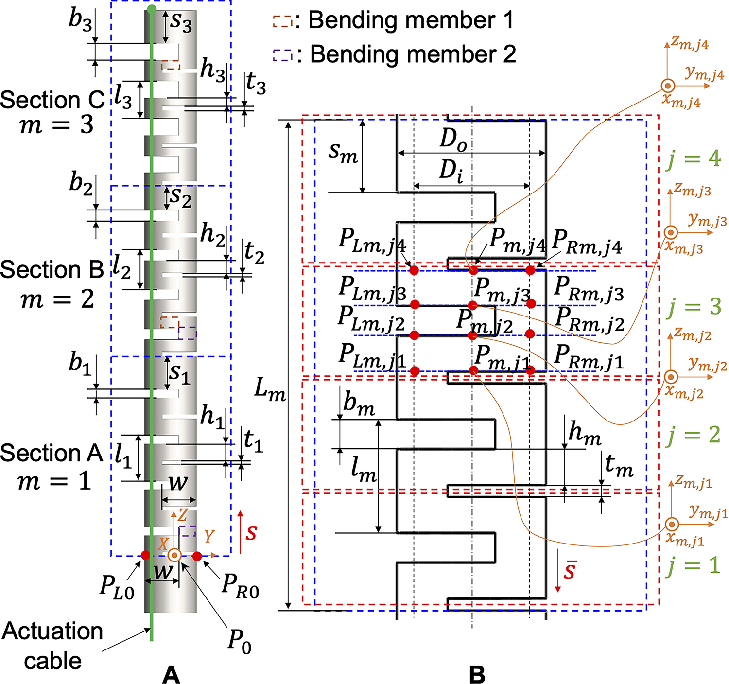
Structural parameters of notched components
As shown in Figure 1, a steerable catheter is typically inserted via the femoral artery in the patient’s leg 33 and potentially to the narrow and tortuous vascular system in the patient’s head and neck. The controlled steering of the catheter across various sharp bifurcations is crucial to ensure a smooth and safe catheterization process. 34 In our work, a cable-driven VSNC is introduced as the steerable robotic catheter in the EI procedure, utilizing a single bending segment with sections of different bending curvatures to achieve enhanced ability in navigating sharp turns. It is also the continuum robot candidate used to validate our proposed state estimation approach. Besides, it is noted that the phantom models (vessels A and B) used in our simulations and experiments were segmented and molded based on the anatomical vessels shown in Figure 1A, B.
Notched-tube structures made from superelastic Nickel Titanium (Nitinol) materials are increasingly being studied in surgical robotics due to their excellent properties of superelasticity and biocompatibility, which can be easily integrated into surgical instruments. 35 A notched-tube continuum robot consists of tubes with strategically cut notches, reducing its stiffness and enabling it to bend at a large angle. 36
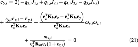
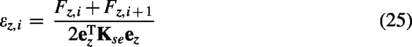
As shown in Figure 2A, the VSNC consists of three different bending sections A, B, and C with outer diameter (


Discretization of the VSNC along the robot arc length.
It is noted that the different structural parameters in sections A, B, and C are essential for achieving variable stiffness and adaptability and can be determined through a combination of our proposed modeling approach, design optimization techniques, 37 and experimental validation.4,38 By adjusting these parameters, we can locally control bending stiffness and flexibility. The proximal section (A) requires higher stiffness for support and force transmission, while the middle and distal sections (B and C), with intermediate and lower bending stiffness, need greater flexibility to navigate complex anatomical pathways in confined spaces.
As shown in Figure 2B, each notch section includes four notch elements (
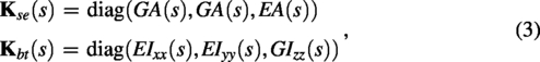
The shear/extension and bending/torsion matrices can be, respectively, expressed as follows:
(
Cosserat-Based Contact Modeling Under Multiple External Constraints
In this section, we derive a new quaternion-based Cosserat contact model for cable-driven continuum robots. Taking into account frictional interaction, material nonlinearity, and environmental contact constraints, the classical Cosserat rod model is modified to accommodate general external loading conditions.
Model assumptions
The basic assumptions of the proposed Cosserat-based contact model are clarified as follows:
As shown in Figure 3, the tendon interactions are assumed to occur only at the edges of each notch element.
39
Therefore, the cable friction forces only exist at the discrete points The angles between The discrete points The bending of the continuum robot is dominated by the different bending members,
40
as indicated by the orange and purple dotted rectangles in Figure 2A. The bending behavior can be tuned by adjusting the structural parameters (e.g.,
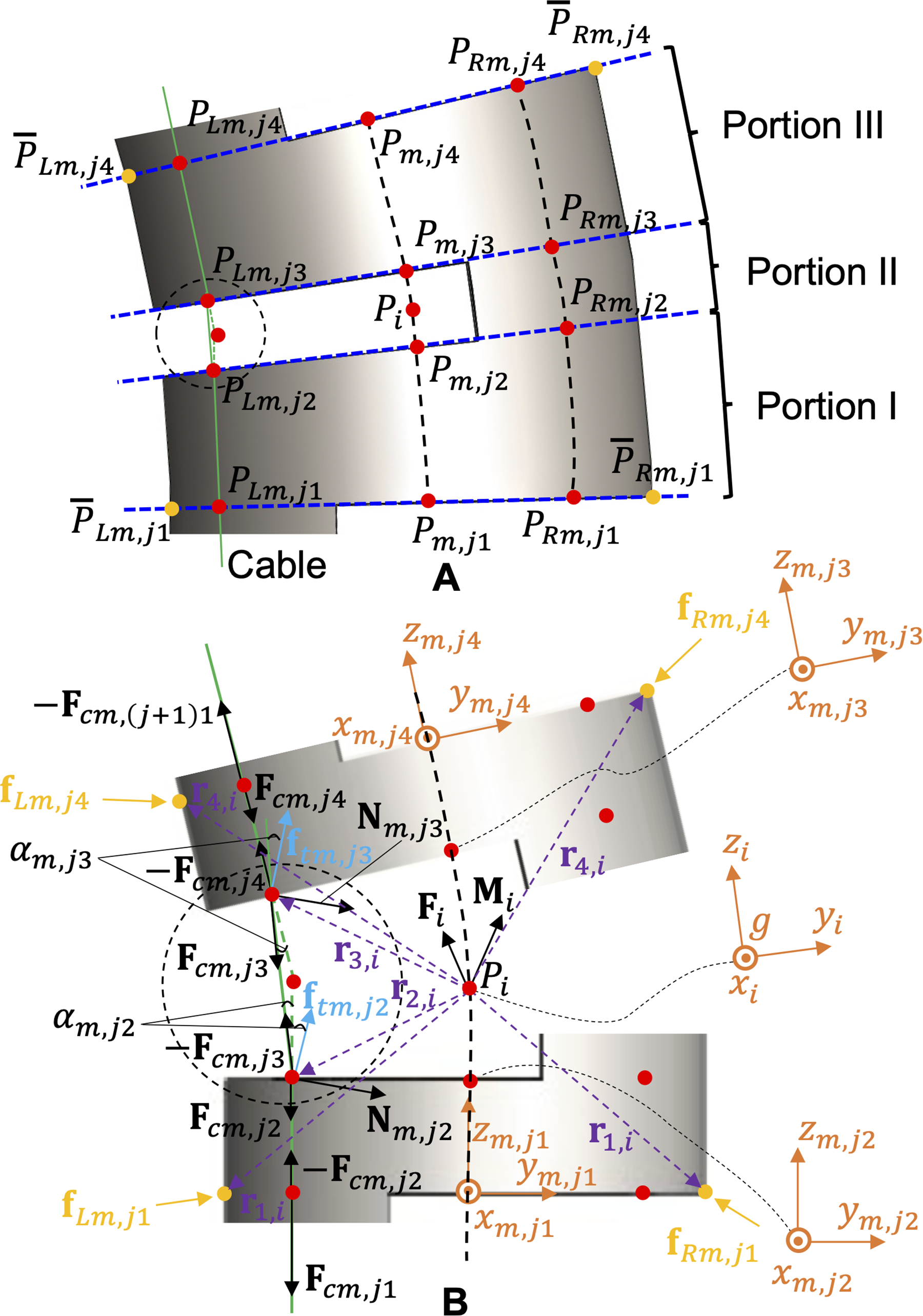
Force analysis of each calculation element.
Cable friction force
As shown in Figure 3B, the scalar forms of friction forces


Hence, the scalar form of normal force

Taking into account the cable force balance equation at discrete point

Material nonlinearity
Nitinol materials exhibit a nonlinear mechanical behavior, leading to hysteresis in the relationship between actuation forces and bending angles.
41
To provide an approximate estimation of the Young’s modulus of the notched-tube robot, our work employs a simplified material model that represents the stress-strain curve using a piecewise linear function35,41 of the Young’s modulus.
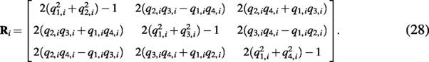
Quaternion-Based Cosserat contact model
In contrast to our previous inextensible Cosserat-based model (i.e.,


The initial strain

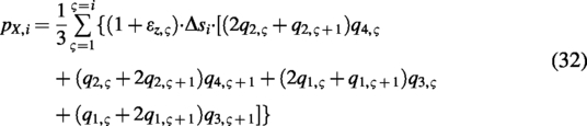
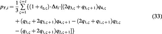
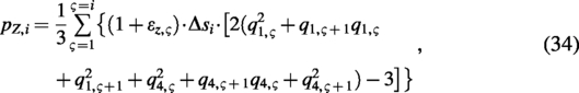
Transforming Eqs. (10)–(11) and discretizing the quaternion-based Cosserat rod model with respect to


In the discretized expression of the proposed contact model,
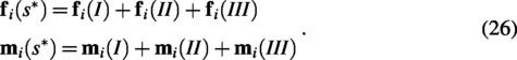
As shown in Figure 3, each notch element on the notched-tube continuum robot is considered as a calculation element in the proposed model. Every calculation element consists of three portions (I, II, and III), with
As shown in Figure 3B,
The bending angle

The total bending angle
Additionally, the directions of body contact forces

Since the robot base is assumed to be aligned with the origin of the global frame G, the position
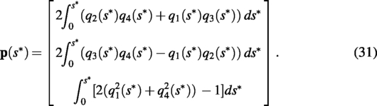
Integrating Eq. (31), the position of the distal endpoint of every calculation element,
Environmental contact constraints
The geometric information of the external environment can be predetermined through sensing techniques, such as magnetic resonance (MR) or computed tomography (CT) imaging. Since our proposed approach assumes the external environmental constraints are fixed and rigid, a single preoperative image reconstruction is sufficient. By applying the Point Inclusion in Polygon Test algorithm, 45 the shape of the external environment can be efficiently extracted from preoperative images. By incorporating the obtained geometric information about the external environment’s shape, constraint equations can be established to estimate the body contact forces with the environment. The majority of external contact constraints can be simplified as a combination of contact constraints involving points, planes, and curved surfaces. The external contact constraints between the robot and the environment are assumed to be static. Continuum surgical robots may encounter multiple types of external contact constraints in minimally invasive treatment. The human vascular system is chosen as a typical example of the external environment in our work. The robot should navigate through the intricate vasculature to achieve a large bending angle during the EI procedure. As shown in Figure 4, in the global frame G, the external constraints between the robot and the vessels, including the point contact constraint, plane contact constraint, and curved surface contact constraint, are included in the proposed Cosserat-based contact model.
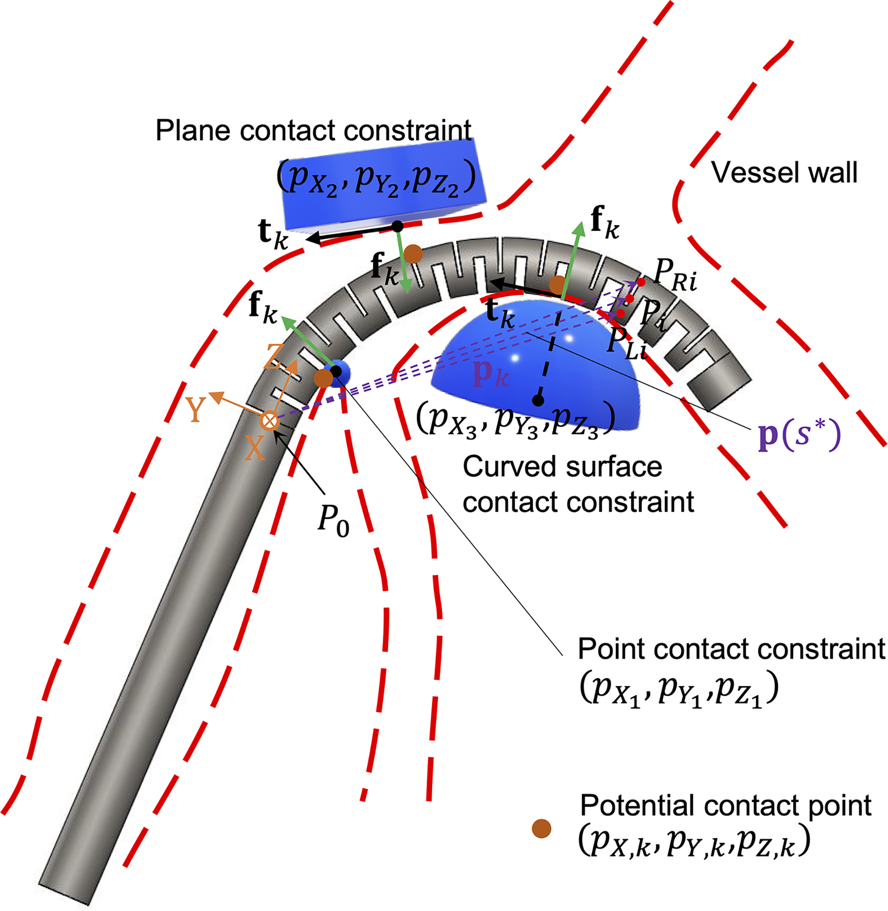
Multiple types of external contact constraints between the continuum robot and the environment, in terms of the point contact constraint, plane contact constraint, and curved surface contact constraint.
Point contact constraint
The relatively sharp contact regions in the external environment can be regarded as point constraints.

Plane contact constraint
The relatively flat and smooth contact regions in the external environment can be treated as plane constraints.

Curved surface contact constraint
The curved or protruding regions in the external environment can be considered as curved surface constraints.
Additionally,
The projection of
Methods
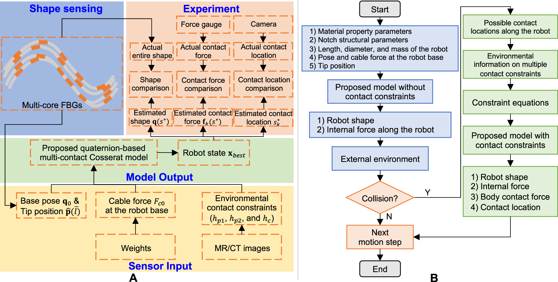
Incorporating the boundary condition and contact force regularization, the solving process of the proposed Cosserat-based contact model is transformed into a nonlinear global optimization problem, which simultaneously estimates both the shape and body contact force for continuum robots. Accounting for the boundary conditions and environmental contact constraints, the overall solving procedure of the proposed state estimation approach for continuum robots is illustrated in Figure 5.
Boundary conditions
The proposed Cosserat-based contact model has mixed boundary conditions. The position of the robot base is fixed at the origin of the global frame G, resulting in
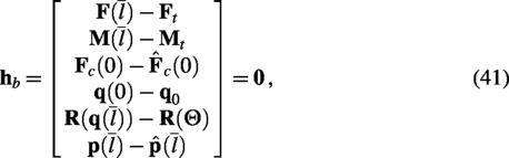
Owing to the z-axial strain along the robot centerline, the length condition of the total arc length of the robot centerline is imposed as follows:
((

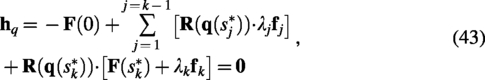
Contact force regularization
Quasi-rod mechanics equilibrium
To enhance the robustness of solving the body contact force, the arc length along the robot, ranging from 0 to
Penalty approach
The penalty approach is employed to reformulate the body contact force
Optimization procedure
The solving process can be regarded as a nonlinear global optimization problem. The proposed Cosserat-based contact model comprises Eqs. (17)–(23), (35)–(37), and (41)–(42). These equations collectively formulate the objective function
The state vector

We first present this as a constrained optimization problem:
((
To convert the constrained optimization problem [Eq. (46)] into an unconstrained one, a penalty function

Figure 5A illustrates the sensor inputs required for solving the proposed contact model, which include the robot base pose
The collision-free robot shape is first estimated by the proposed model in an obstacle-free environment and under a geometrically unconstrained condition [i.e., without Eqs. (35)–(37)]. The robot contact portions of possible collisions between the collision-free robot shape and the external environment can be selected either manually by the user or automatically by the solver. Then, the corresponding discretized segments relative to the contact regions on the robot are determined to be subject to the external contact constraints [i.e., Eqs. (35)–(37)]. This can result in more efficient computations for the proposed model when considering the external contact constraints. As illustrated in Figure 5B, the detailed solving procedure for the proposed state estimation approach can be outlined in the following three steps:
Additionally, in the process of solving the proposed contact model, the body contact force status is employed to determine whether the continuum robot collides with the external environment at possible contact locations within the potential collision segments. Specifically, if the body contact force
Simulation results
The cable-driven VSNC is necessary to navigate through the intricate internal carotid arteries in the neck during the target case study of the EI procedure. The variable stiffness of the robot provides a variable-curvature motion during navigation in the vessels. It offers a low curvature of bending motion to navigate through a flat vessel. However, it must also be able to achieve a large bending angle to access another vessel branch at a confined blood vessel corner.
Based on the complex geometric shape of the arteries that the VSNC would need to navigate through in the EI procedure, the proposed state estimation approach for the VSNC is evaluated using two distinct cases (Case I and Case II). Case I is subject to both point and plane constraints, while Case II is subject to both plane and curved surface constraints. According to the structural parameters of the target internal carotid arteries in the vascular system
46
based on patient data, the constrained external environment maps of the two clinical scenarios, Case I and Case II, were obtained, as shown in Figure 6A, B. This process involved segmenting the anatomy to generate a point cloud map, which was then used to create a constraint map, and eventually, an environment map.
Generation of the constrained environment maps for the clinical scenarios of Case I 
As depicted in Figure 6A, B, by fitting the extracted points on the boundary in the segmented map, the specific standard equations of the constraint point, constraint plane, and constraint curved surface in the global frame G can be, respectively, expressed as follows:
Constraint point:
(( Constraint plane:
(( Constraint curved surface:
((


In both Case I and Case II of the simulation experiments, the VSNC is required to navigate and access another vessel branch near a confined blood vessel corner with a large bending angle. It is noted that the tip positions of the VSNC for the simulation experiments were obtained from the real-world experiments.
Case I: Contact estimation under the point and plane constraints
In Case I, as shown in Figure 6C–I, the VSNC encounters only the point and plane contact constraints during the endovascular navigation in the vessel A. Seven motion steps were selected to demonstrate the estimates, including the body contact force and the robot shape, between the VSNC and the vessel during the navigation. In Case I, the robot navigates from branch 1 to branch 2 in the vessel A. As the VSNC moves forward and bends to the right (branch 2), the robot first makes contact with the constraint point, and its body contact force gradually increases to ∼301 mN, as shown in Figure 6G. The olive green arrow represents the estimated body contact force. Subsequently, the robot simultaneously makes contact with both the constraint point and the constraint plane (see Fig. 6H), causing the contact force near the constraint point to gradually decrease, while the contact force on the constraint plane increases to ∼246 mN (see Fig. 6I). Finally, the VSNC successfully bends from branch 1 to branch 2, achieving a maximum bending angle of around 150 degrees.
Case II: Contact estimation under the plane and curved surface constraints
In Case II, the VSNC navigates from branch 3 to branch 4 in the vessel B, as shown in Figure 6J–P. In this instance, the curved surface and plane contact constraints arise during the endovascular navigation of the robot in the vessel B. In comparison with Case I, in Case II, the constraint point is replaced by a constraint curved surface. As shown in Figure 6M, the maximum body contact force at the bend of the blood vessel was reduced to 133 mN (
Computation time analysis
The simulation experiments were conducted using MATLAB R2023a installed on a DELL desktop computer equipped with a 13th Generation Intel Core i7-13700 CPU running at 2.10 GHz and 32.0 GB of RAM. On the aforementioned specified computational platform, each shape and force estimation takes ∼60–90 s. Additionally, in multicontact scenarios, poorly chosen initial values can significantly affect the convergence efficiency of our estimation approach. Although we employ a trust-region-based solver 42 that promotes convergence by iteratively updating and scaling the gradient, the nonconvex nature of our optimization problem can lead to convergence time exceeding 10 min when the initial value is poorly chosen (e.g., significantly deviating from the no-contact model solution).
Experiments and Results
Experimental setup
In the experiments, a prototype of the VSNC was developed to obtain measured shape and contact force data, which can then be compared with the simulation results. The VSNC features structural parameters as follows:
To demonstrate the contact motion of the VSNC in the target case study of the EI procedure, a vessel phantom was employed to represent the intricate shape of the internal carotid arteries within the vascular system, as shown in Figure 7B. Based on the geometric shapes of the two simulated vessels described in the previous section, the vessel phantom was fabricated from silicone materials using a molding technique. 47 The vessel phantom consisted of vessel A (with point and plane contact constraints) and vessel B (with curved surface and plane contact constraints), corresponding to the simulated clinical scenarios of Case I and Case II in the previous section. The vessel wall thickness in the phantom was set to 1 mm, which is similar to the mean value of the wall thickness of the internal carotid arteries in the vascular system. 46 To ensure the relative orientation and position between the vessel phantom and the VSNC are consistent with the simulations, the linear translation stages I and II, along with the rotation stage, were utilized to calibrate the pose between the vessel phantom and the VSNC.
As shown in Figure 7A, a multicore FBG fiber was placed at the central lumen of the VSNC with a robust sensing algorithm 48 to obtain the ground truth of the robot shape. The measured tip position from the FBG sensor would serve as input information for the proposed Cosserat-based contact model. While the FBG sensor enabled full shape sensing, its main purpose was to offer ground-truth data for validating the shape estimated by our approach. The FBG sensing system, including a multicore FBG fiber, a fan-out box (FBGS, Belgium), and an FBG interrogator (RTS 125+, Sensuron, USA), was integrated within the lumen of the VSNC for shape sensing. The spatial resolution (i.e., spacing distance) between two adjacent FBG sets of the multicore FBG fiber is 3.3 mm. The body contact force along the robot was measured by a force gauge (SF-3, AIPU, China). The force gauge was mounted on the linear stage III to adjust its position and orientation relative to the vessel phantom for measuring the contact force. The maximum load and resolution of the force gauge are 3 N and 1 mN, respectively. The pointed and flat contact heads were then implemented to measure the contact forces under the point/curved surface contact constraint and the plane contact constraint, respectively. The camera (MV-CS060-10GM, Hikvision, China) was employed to record the navigation motion of the VSNC. According to the recorded snapshot of the VSNC motion, the contact points (denoted by the orange dots in Fig. 7A) along the VSNC were manually determined by counting the robot notches nearest to the contact head. Additionally, the contact points were double-checked with the force gauge to ensure that the maximum contact force occurred at the potential contact points. The measured contact location was then calculated by the total arc relative to the contact notch from the robot base at G. The red arrow in Figure 7B indicates the direction of motion during the navigation of the VSNC in the experiment.
Parameter calibration
To identify the parameters in the proposed state estimation approach, the VSNC was actuated under both loading and unloading procedures in free bending. The proximal cable force
Figure 8 demonstrates that the proposed model accurately replicates the experimental results during the bending motion of the VSNC. As shown in Figure 8A, B, the estimated shapes from the proposed Cosserat-based model were consistent with the measured shapes obtained from FBG sensing during both the loading and unloading procedures. The mean and maximum shape deviation errors during the loading procedure were 0.228 and 0.550 mm, respectively. In the unloading procedure, the mean and maximum shape deviation errors were 0.351 and 0.993 mm, respectively. As shown in Figure 8C, the VSNC achieves a bending angle of ∼169°. The proposed model predicts a broader hysteresis range of the bending angle compared with the experimental data. This discrepancy arises from an error in solving for the quaternions, where the quadratic sum of the quaternions (i.e.,
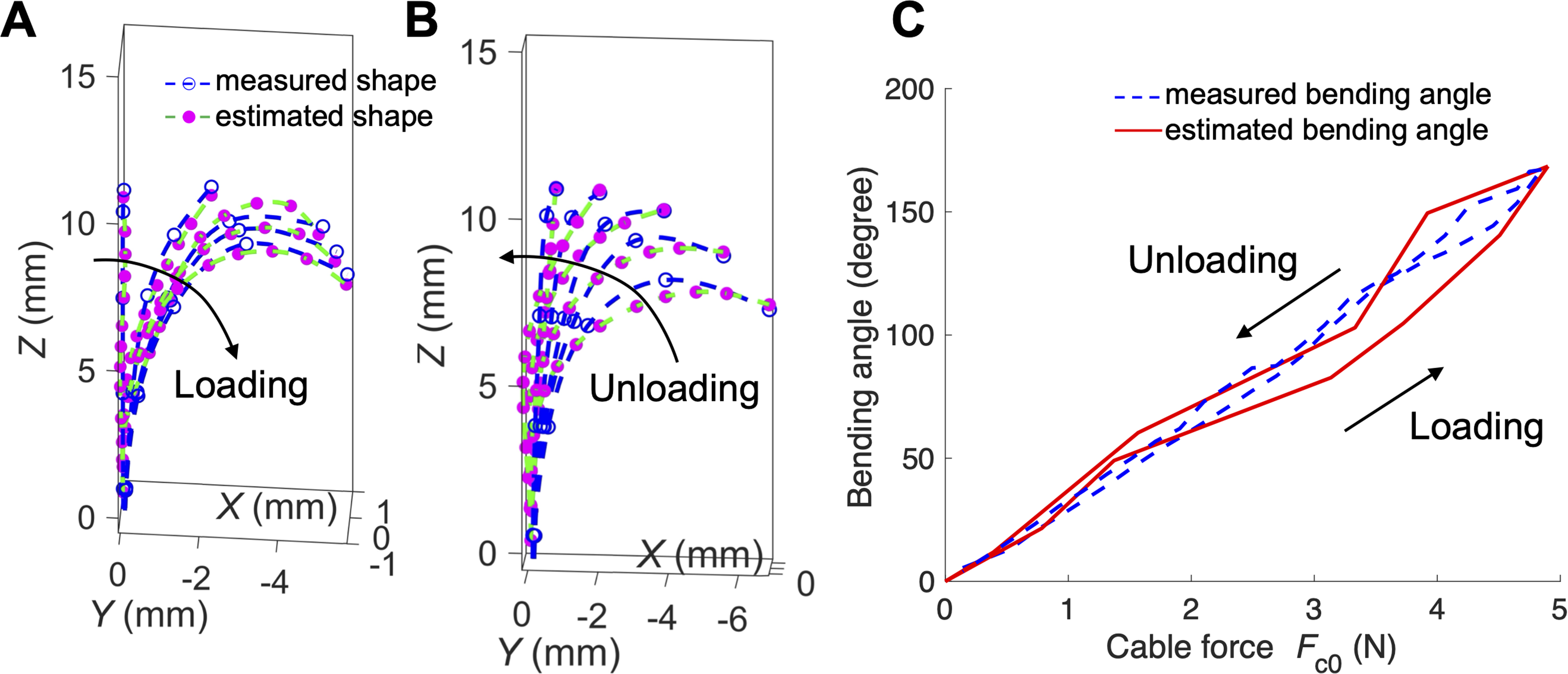
Results from the parameter calibration procedure.
Experiment 1: Contact estimation validation under the single and multiple point contact constraints
In Experiment 1, the contact estimation for the VSNC initially accounted for single and multiple point contact constraints, as shown in Figure 9. The external point loads were determined by hanging known weights at specific locations using the pulleys. The magnitude of the arbitrary external point load j (denoted by
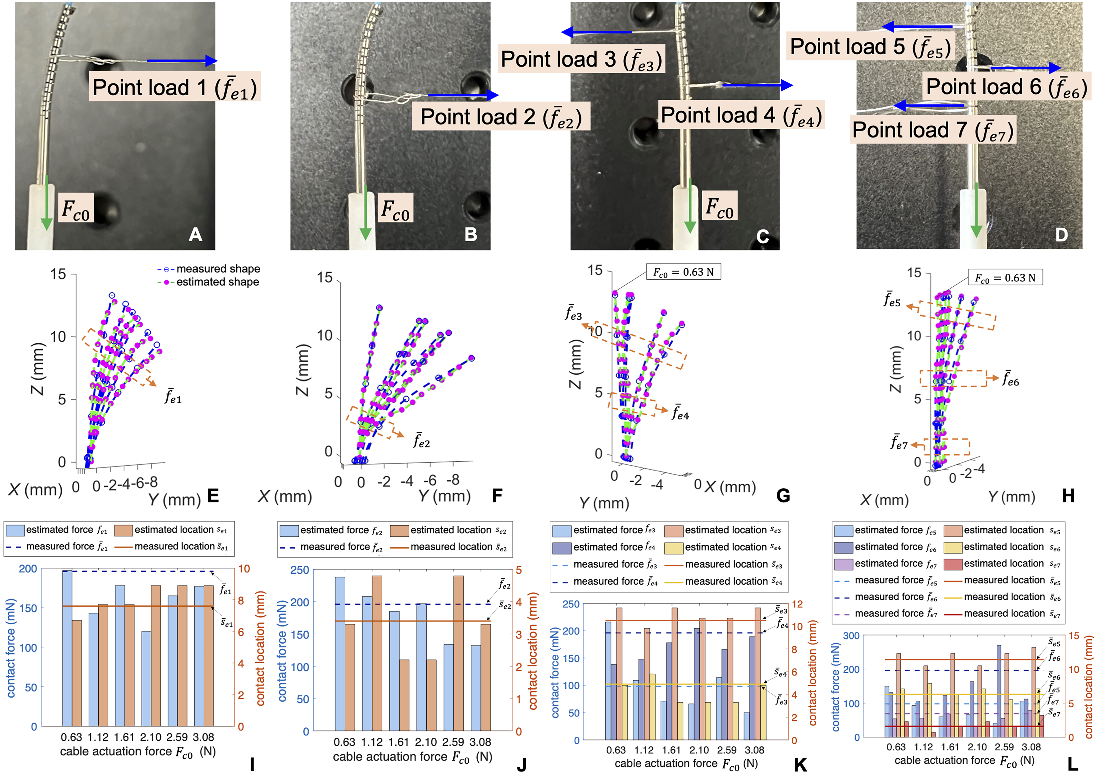
Contact estimation experiment under single and multiple point contact constraints.
As shown in Figure 9E, F, the mean and maximum shape deviation errors under load 1 were 0.566 and 1.17 mm, respectively, while under load 2, they were 0.402 and 1.21 mm, respectively. In the experiment under the single point contact constraints, the results of the contact estimation are shown in Figure 9I, J. In the case of point loads 1 and 2, the mean absolute magnitude error of the body contact force was 32.5 mN, while the mean absolute contact location error was 0.91 mm. The estimated contact force magnitude achieved a level of accuracy similar to that of the experiment conducted on a cantilevered slender rod with a predetermined FBG-sensed shape and without internal actuation consideration, as reported in the SOTA work 19 (52.01 mN).
As shown in Figure 9C, in this case of the multiple point contact scenario involving two point loads, the two point loads (
As shown in Figure 9D, a triple-contact scenario involving three external loads [point load 5 (
Experiment 2: Contact estimation validation in the clinical scenario
In the contact estimation for the clinical scenario, vessel phantom A (which includes point and plane contact constraints in Case I) and vessel phantom B (which features curved surface and plane contact constraints in Case II) were used to validate the contact estimation for the out-of-plane (i.e., three-dimensional) manipulation of the VSNC. As shown in Figure 10, a polyethylene (PE) tubing with an outer diameter of 0.7 mm and an inner diameter of 0.35 mm is embedded in the VSNC to house the FBG sensor. This blue tubing extends slightly beyond the robot. This design allows the FBG fiber to pass through the narrow channel in the blood vessels in advance, ensuring that the tip of the FBG fiber is not disturbed during the robot’s movement, thereby improving the accuracy of shape measurement. As shown in Figure 10A–F, the endovascular navigation procedure of the VSNC was performed in the vessel phantom A, navigating from branch 1 to branch 2. Similarly, in the second clinical scenario, the endovascular navigation procedure of the VSNC was conducted in the vessel phantom B, moving from branch 3 to branch 4, as shown in Figure 10G–L.
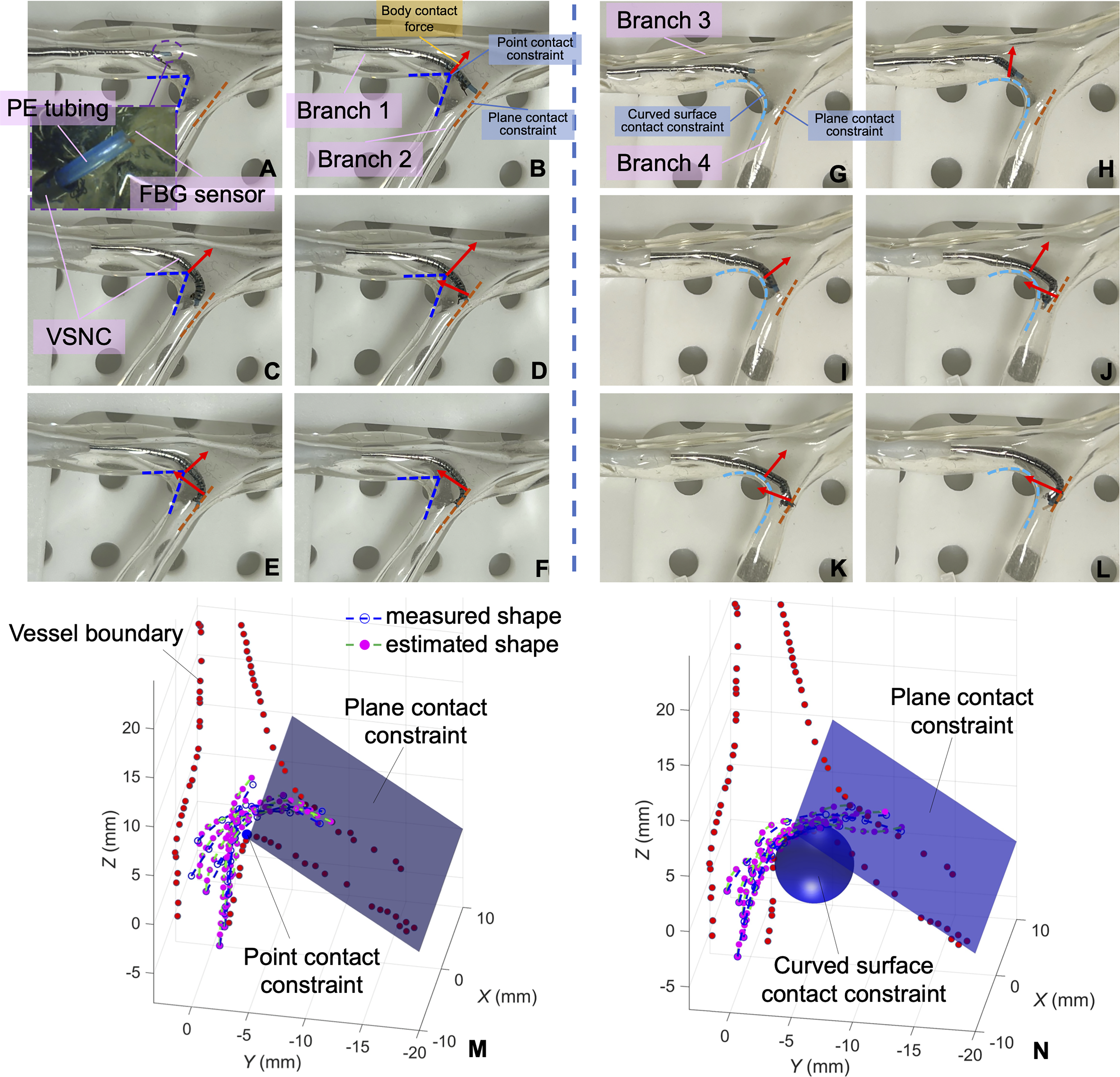
In the experiment of the first clinical scenario (Case I),
Clinical Case I
In the experiment of Case I, the results of the contact estimation under the point and plane contact constraints (Case I) are shown in Table 1. The mean absolute magnitude error of the body contact force was 34.4 mN, while the mean absolute contact location error was 1.06 mm. As shown in Figure 10M, the mean and maximum shape deviation errors in Case I were 0.514 and 1.66 mm, respectively. It can be seen that the proposed estimation approach can also achieve high accuracy in three-dimensional cases.
Clinical Case I with Point and Plane Contact Constraints: Estimated (
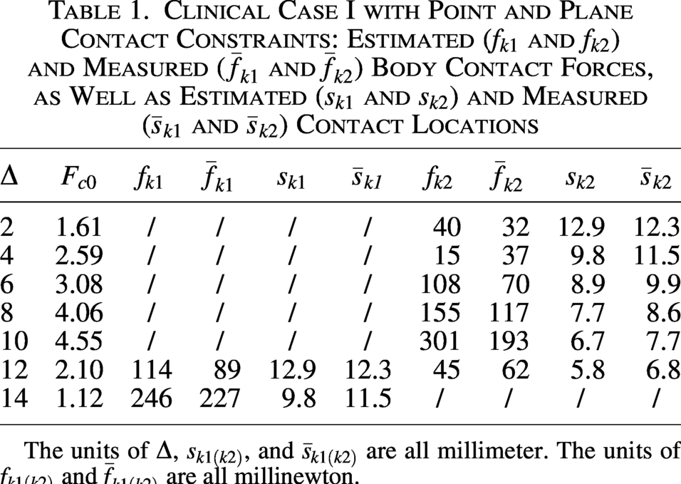
The units of Δ,
Clinical Case II
The estimates for Case II under the curved surface and plane contact constraints are shown in Table 2. The mean absolute magnitude error of the body contact force was 21.3 mN, and the mean absolute error in contact location was 1.24 mm. Compared with the robot estimates in Case I, the contact force on the constraint curved surface was lower than that on the constraint point. This is because the constraint point creates a sharper turn in the blood vessel, which poses a greater hindrance to the navigation of the VSNC. As illustrated in Figure 10N, the mean and maximum shape deviation errors in Case II were 0.359 and 0.965 mm, respectively. Due to the larger contact area of the constraint curved surface compared with the constraint point, in VSNC navigation, most of the robot shapes were enveloped by the constraint curved surface, leading to smaller shape deviation errors compared with Case I.
Clinical Case II with Curved Surface and Plane Contact Constraints: Estimated (
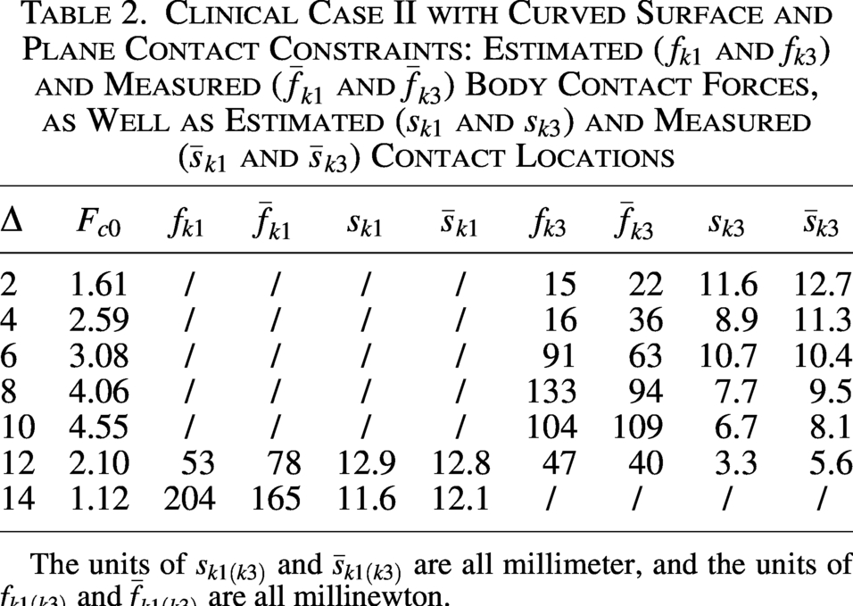
The units of
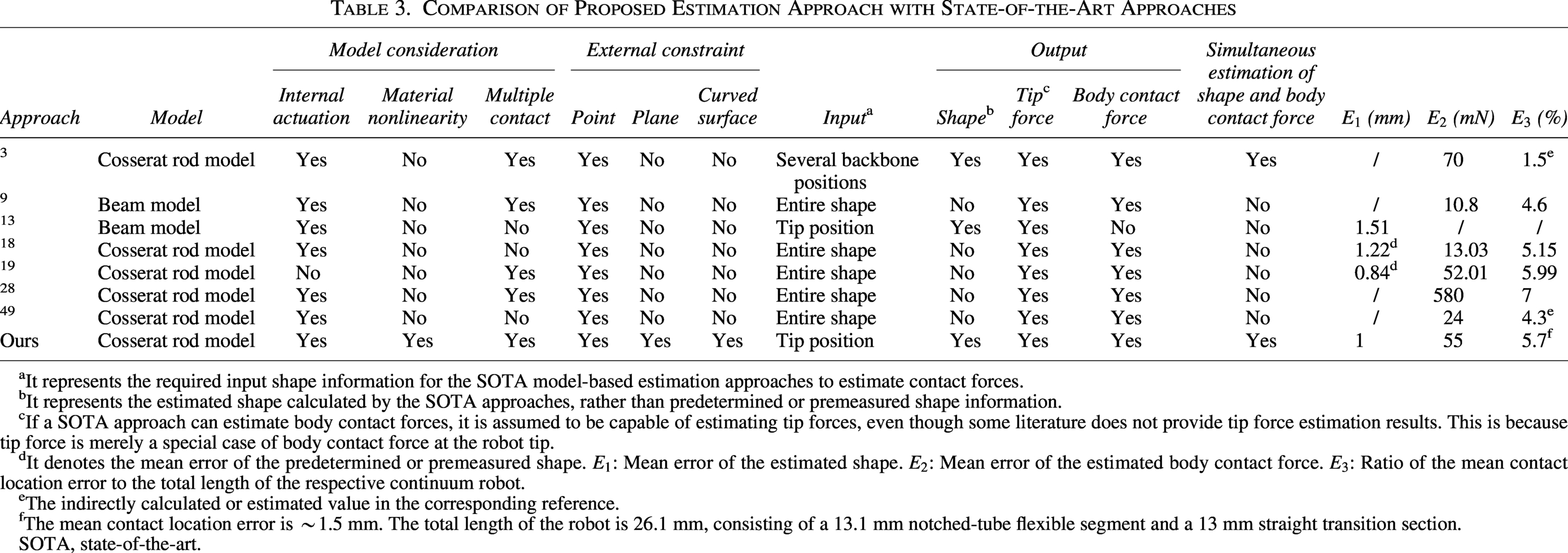
Performance comparison with SOTA approaches
Table 3 presents a performance comparison between the proposed estimation approach and SOTA estimation methods. Continuum robots often navigate confined environments (e.g., blood vessels and tracheobronchial trees), where external structures impose complex geometric constraints on their motion. Additionally, due to the cable friction interaction and superelastic properties of robot materials (e.g., Nitinol tubes), notched-tube continuum robots often exhibit nonlinear behavior, making linear material assumptions inaccurate. Besides, in contrast to Euler–Bernoulli beams and previous Cosserat-based models, which focus on tip force estimation, assume a single contact point, or require the entire shape as input, our proposed quaternion-based Cosserat model accounts for shear deformation, axial stretch, and distributed loads, making it more suitable for highly complex contact scenarios. Therefore, in this work, we have explored the simultaneous estimation of shape and body contact force of continuum robots, while considering key factors such as complex external geometric constraints (e.g., curved surface contact), internal actuation, material nonlinearity, and multicontact interaction.
Comparison of Proposed Estimation Approach with State-of-the-Art Approaches
It represents the required input shape information for the SOTA model-based estimation approaches to estimate contact forces.
It represents the estimated shape calculated by the SOTA approaches, rather than predetermined or premeasured shape information.
If a SOTA approach can estimate body contact forces, it is assumed to be capable of estimating tip forces, even though some literature does not provide tip force estimation results. This is because tip force is merely a special case of body contact force at the robot tip.
It denotes the mean error of the predetermined or premeasured shape.
The indirectly calculated or estimated value in the corresponding reference.
The mean contact location error is ∼1.5 mm. The total length of the robot is 26.1 mm, consisting of a 13.1 mm notched-tube flexible segment and a 13 mm straight transition section.
SOTA, state-of-the-art.
As shown in Table 3, it is clearly seen that the proposed method can achieve a comparable level of estimation accuracy to Cosserat-based estimation approaches.3,19 Although providing complete and accurate robot shape information as the input can greatly improve the accuracy of contact force estimation, obtaining full shape data is often challenging in scenarios with stringent miniature robot size requirements, such as in continuum surgical robots. Our method overcomes this limitation by enabling the simultaneous estimation of the shape and body contact force using only minimum shape input information (i.e., tip position). Although a multicore FBG fiber was used in our experiments for full shape sensing, its main role was to provide ground-truth data for validating our estimated shape. The FBG-based tip position used in our approach can equally be obtained with electromagnetic (EM) sensors or commonly used medical imaging modalities such as X-ray fluoroscopy. Thus, our method enables contact force estimation using only tip sensing, reducing overall robot complexity and minimizing the need for advanced shape sensing.
Discussion
Among the most recent works on state estimation in continuum robots, it is notable that only a few SOTA approaches 19 can achieve real-time estimation performance, primarily because the entire robot shape is predetermined as a prerequisite. Other Cosserat-based estimation approaches,3,9,49 including our method, are unable to achieve real-time performance due to the necessity of solving the additional shape within the coupled state estimation procedure. The nonconvexity of our optimization problem [Eq. (47)], caused by complex nonlinear constraints and multiple coupling terms, significantly contributes to the runtime. This limitation could potentially be mitigated through approximate convex reformulation, the integration of efficient search strategies, and parallel computing. Besides, by implementing the proposed method in programming languages such as C/C++ and deploying it on more advanced hardware, its performance could be significantly enhanced, potentially enabling real-time applicability.
Additionally, among the most recent works on force sensing in continuum robots, only Gao and Lin et al.
9
have explicitly elaborated the effect of the distance between two adjacent contact points, making it a pioneering contribution in the field. Accurate force estimation becomes challenging when the distance between two adjacent contact points is smaller than 5 mm.
9
A similar phenomenon is observed in our approach, where the force estimation error increases when the distance between two adjacent contact points is less than
Conclusion
In this work, a deterministic model-based estimation approach is proposed to simultaneously estimate both the robot shape and body contact force for continuum robots. Specifically, accounting for internal actuation, frictional interaction, material nonlinearity, and multiple environmental contacts with different geometric constraints, a quaternion-based Cosserat multicontact model is proposed and validated using a typical type of continuum robots (VSNC). This approach is numerically stable and can be applied to a broader range of Cosserat-based problems involving multiple and mixed contact estimation. In future work, the proposed contact model requires validation in scenarios with more than three simultaneous contact points. To address the challenge of acquiring the external environment’s shape in real time, we will integrate intraoperative imaging and a real-time deformation model of anatomical structures into our approach to enable real-time computational performance. Additionally, since our approach has so far only been tested on a planar continuum robot, it should be further validated on spatial continuum robots to fully evaluate its capability in estimating three-dimensional external forces.
Authors’ Contributions
J.C.: Conceptualization, estimation, simulations and experiments, and writing—original draft. Y.L.: Assistance in the FBG-based shape sensing. J.Y.: Fabrication of the notched-tube continuum robot. Y.-H.L. and S.S.C.: Supervision, formulation of the proposed approach, and financial support. S.S.C.: Conceptualization, review and editing.
Footnotes
Author Disclosure Statement
No competing financial interests exist.
Funding Information
Research reported in this work was supported in part by Research Grants Council (RGC) of Hong Kong (CUHK 24201219, CUHK 14217822, CUHK 14207823, AoE/E-407/24-N), in part by Innovation and Technology Commission of Hong Kong (ITS/235/22, ITS/225/23, MHP/096/22), in part by Multi-Scale Medical Robotics Center, InnoHK, Hong Kong, and in part by The Chinese University of Hong Kong (CUHK) Direct Grant. The content is solely the responsibility of the authors and does not necessarily represent the official views of the sponsors.
Supplemental Material
Supplemental Material
Supplemental Material
References
Supplementary Material
Please find the following supplemental material available below.
For Open Access articles published under a Creative Commons License, all supplemental material carries the same license as the article it is associated with.
For non-Open Access articles published, all supplemental material carries a non-exclusive license, and permission requests for re-use of supplemental material or any part of supplemental material shall be sent directly to the copyright owner as specified in the copyright notice associated with the article.