
Abstract
Biohybrid robots actuated by living cells/tissues, a soft robot system that integrates many advantages of life systems and mechanical systems, are promising candidates for developing a new generation of biomedical and environmental monitoring robots. However, due to the limited muscle contraction performance and lack of flexible muscle contraction modes, biohybrid robots’ low speed and flexibility have become a major challenge for their application. To overcome the limitation, different from the existing contraction mode along the longitudinal axis with pulse stimulation, we firstly adopted the square wave stimulation on triceps femoris tissue with pennate fibers arrangement from bullfrogs and found a novel muscle swinging mode with high flexibility and controllability. Based on it, we developed a biomimetic crawler actuated by triceps femoris tissue. The crawler achieved fast forward movement (average speed: ∼6.19 mm/s; maximum speed: ∼7.35 mm/s) and flexible turning ability (∼14.77°/s and ∼9.55°/s for left and right turning speed, respectively) in a liquid environment at room temperature. We believe that the results provide valuable references for the development of soft robots driven by muscle tissue and pave the way to fulfill lifelike motions and break through limitations in conventional biohybrid robots.
Introduction
Biohybrid robots are a new type of robot that combines biological materials with artificial materials.1,2 Therefore, biohybrid robots are expected to have high energy efficiency, high power-to-mass ratio, high load ratio, self-healing, and other biological characteristics, as well as high precision, strength, repeatability, and other mechanical functions.3,4 The biohybrid robots driven by natural or artificial muscle tissue have achieved several simple biomimetic movements, including crawling, 5 swimming, 6 pumping, 7 and gripping, 8 with great potential for application in environmental monitoring, biomedicine, and other fields.9,10
Currently, there are types of biohybrid robots such as cellular robots, muscle tissue robots, and full animal robots. Here, we focus on robots driven by living cells/muscle tissue. The movement of biohybrid robots mainly relies on the contraction of living cells/muscles. Living cells/muscles are the core components of robots, and their performance has become a key factor in the performance of robots. Conventionally, biohybrid robots use artificial mammalian muscle cells,11,12 which contract under electrical or light stimulation with a force of a few hundred micronewtons and a displacement of a few tens of micrometers, resulting in robots moving at a speed of micrometers per second. In addition, almost all studies have used pulse electrical stimulation, which can only produce unidirectional muscle contraction along with the long axis. The single and inflexible muscle contraction mode that greatly limits the structural design and movement modes of the robot. Most robots can only perform forward movement and cannot perform other movements, such as turning.13,14 Thus, it is difficult for biohybrid robots to perform tasks in complex environments. Regarding the issue of contraction performance of cells/tissues, researchers have used tissue engineering methods such as mechanical stimulation, 15 electrical stimulation, 11 and the addition of some nanomaterials16–18 to improve the contraction force of muscle cells. However, owing to the biological characteristics of muscle cells themselves, the improvement in contraction performance is still limited. Regarding the issue of flexibility, some researchers used a robot structure driven by multiple muscles and differentiated stimuli to achieve forward and turning movements.15,19,20 This structure, which increases the volume and weight of the robot, makes it difficult for the muscles to drive, resulting in low turning speed and a large turning trajectory of the robot. There is a concern that the robot may be unable to be utilized in areas with many obstacles that require small-scale turning. In addition, some researchers have developed new stimulation modes that utilize local light/electrical stimulation to achieve more complex motion and improve the robot’s locomotor flexibility.5,21 Therefore, there is an urgent need to develop novel stimulation modes to generate new muscle contraction and deformation modes to improve flexibility to overcome the limitations of existing robots.
Compared with artificial muscle tissue, natural muscle tissue has significant advantages in terms of contractile force, strain, and contractile behavior with multiple degrees of freedom. Specifically, the muscle tissue of bullfrogs has a contractile force of several newtons (∼5 N for the Gracilis muscle of the bullfrog under 3–5 V electrical stimulation), which is hundreds of times greater than that of artificial muscle tissue (∼1 mN for the artificial muscle ring or strip under 3–5 V electrical stimulation). More importantly, bullfrog muscle tissue exhibits distinctive directional contraction characteristics by selective electrical stimulation. 5 Researchers have developed biohybrid walking 5 and swimming 22 robots using bullfrog muscle tissues, which have achieved excellent performance. Moreover, the environmental requirements for amphibians are relatively simple compared with mammalian cells/tissues, allowing them to perform tasks in a wider range of environments. Specifically, in terms of temperature, 23 amphibian cells are typically cultured at room temperature (20–25°C) without the need for thermostatic equipment. In terms of gaseous environments, amphibian cells are adapted to air environments without the need for CO2 incubators. On the contrary, mammalian cells have strict requirements for temperature and gas environment. The cells must be at a constant temperature of 37°C and a 5% CO2 gas environment. Otherwise, their performance will be greatly affected. Moreover, compared with mammalian cells, amphibian cells are more tolerant to pH fluctuations, temperature variations (15–28°C), and have lower nutrient requirements for the culture medium. 24 This provides a superior foundation for performing tasks in outdoor room temperature environments. Thus, bullfrog muscle tissues are promising candidates to address the challenges of existing biomaterials.
In this study, we dissected the leg muscles of bullfrogs and found that the posterior part of the triceps femoris tissue had an outstanding contractile force and distinctive bidirectional swinging contraction characteristics under square–wave stimulation. Inspired by the similarity between the bidirectional swinging of muscle and the movements of bipedal animals such as humans (Fig. 1A), we designed a centimeter-scale biomimetic crawler (Fig. 1B, Supplementary Fig. S1) actuated by triceps femoris tissue. Tissue contraction is controlled by applying specific electrical stimulation with electrodes. Driven by the bidirectional swinging of muscle under electrical stimulation, the crawler alternately moves forward with its left and right feet to achieve rapid movement (Fig. 1Ci). In addition, the crawler achieved controllable turning by changing the stimulation mode (Fig. 1Cii).
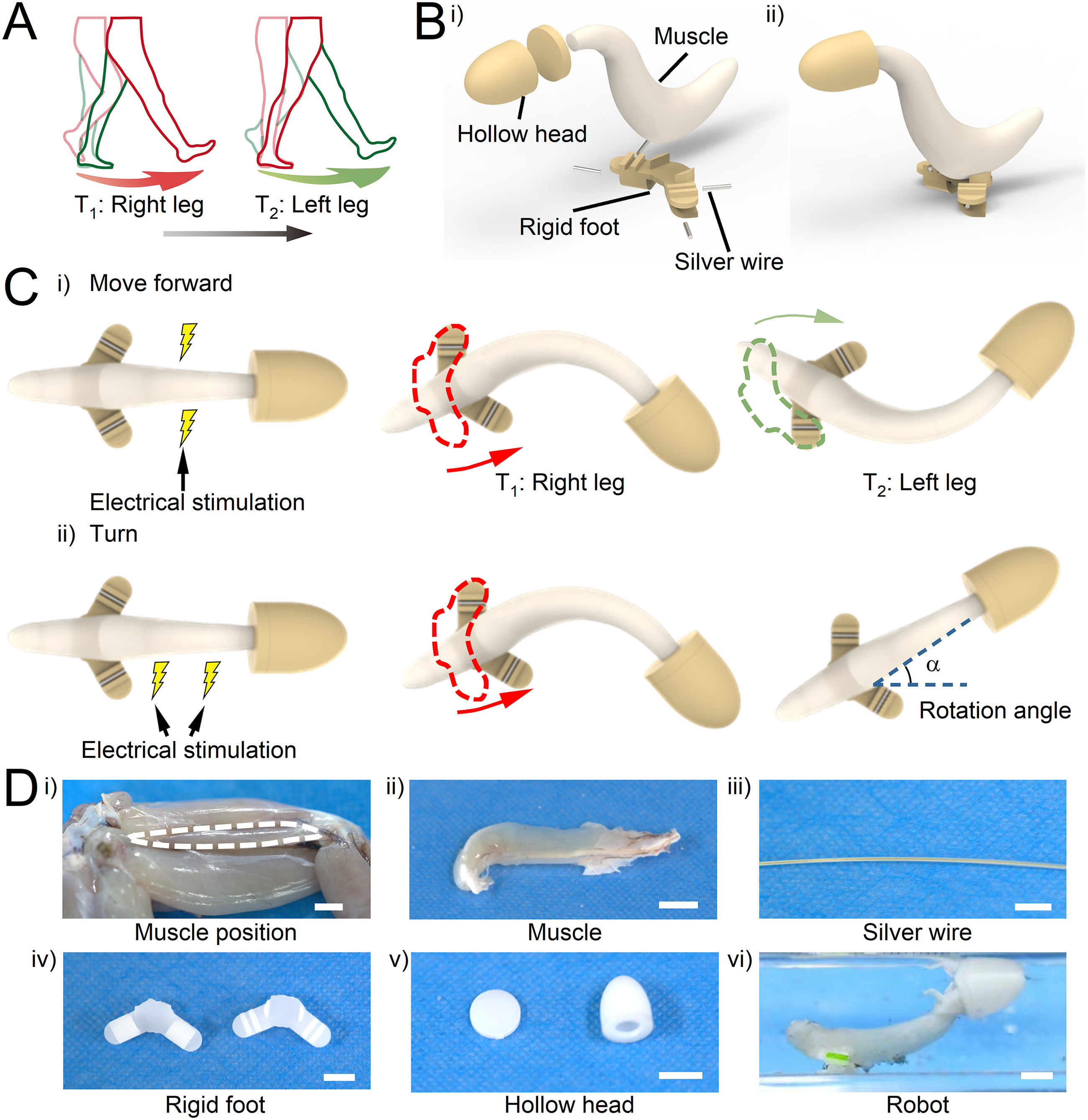
Construction of a biohybrid crawler powered by triceps femoris tissue from the bullfrog.
Materials and Methods
Muscle removal and maintenance
The surgical removal of frog tissues designated for robotic actuation was performed according to the procedures approved by the Committee on Animal Care of Xi’an Jiaotong University. Adult bullfrogs with a weight from 140 to 300 g were pithed. For each bullfrog, the tissues were dissected from both hind limbs, measured, and weighed after removal. Before harvesting the muscles, Ringer’s solution (PB180342, Procell, China) was prepared, which comprised of CaCl2 120 mg/L, KCl 140 mg/L, NaHCO3 200 mg/L, NaCl 6500 mg/L, NaH2PO4·2H2O 13 mg/L, and
Fabrication of biohybrid robots with triceps femoris tissues
The mechanical skeleton of the robot was composed of a hollow head (Fig. 1Dv), rigid skeleton foot (Fig. 1Div), and silver wire (Fig. 1Diii). The hollow and rigid skeleton foot was manufactured using a commercial stereolithography modeling machine (SPS600B, Hengtong) from a photoreactive acrylate resin (R11, EnvisionTEC). The hollow head used to provide buoyancy was glued (Loctite, Germany, 4902) together by two components. Silver wire was added to the rigid foot to increase weight and improve structural stability. Afterward, we used glue to bond the hollow head and one end of the muscle, as well as the rigid foot and the other end of the muscle (Fig. 1Dvi). The total amount of time between muscle removal from the animal to finalizing the muscle installation into the robots was approximately 15 min.
Contractility evaluation of triceps femoris muscle tissues
To investigate the function of the triceps femoris muscle tissues as actuators, we evaluated their contraction performance systematically, including muscle strain, rotational ability, and contractive behavior under different electrical stimuli. Before the experiment, we developed postprocessing software that can track and analyze muscle strain and rotational ability through marker points. After acquiring muscles, five green wooden pieces were glued onto the surface of the muscles as tracking markers. Then we put the tissue into a rectangular chamber with Ringer’s solution and aligned it with a grid ruler under the chamber. The electrical signal was generated by a generator (DG812, RIGOL, China) and applied to graphite electrodes fixed on both sides of the chamber (Fig. 3A). The electrical field of the square wave signal was adjusted from 0.5 to 2.5 V/cm (Amplitude: 0.5, 1, 1.5, 2, and 2.5 V/cm, frequency: 1 Hz). Then the frequency of the square wave signal was changed from 0.5 to 3 Hz (Amplitude: 1.5 V/cm, frequency: 0.5, 1, 2, and 3 Hz). Then we applied a pulse signal to the muscle (Amplitude: 1.5 V/cm, Frequency: 1 Hz, duration: 10 ms). Finally, we performed square wave electrical stimulation (Square wave, amplitude: 1.5 V/cm, frequency: 1 Hz) on the left and right sides of the muscle tissue. The muscle contraction behaviors were recorded with a video camera (A7S3, Sony) and analyzed with the postprocessing software. In addition, we avoid the negative effects of electrolysis by regularly changing the medium.
Determination of the coefficient of friction of robot feet and container bottom
First, we prepared the robot foot with silver wire and then placed it on the bottom of a container with Ringer’s solution. The container was placed on a platform that could be inclined with an initial inclination angle of 0°. Second, we slowly increase the inclination angle of the platform until the robot foot naturally slides down in the container, and record the inclination angle (θ). The corresponding friction coefficient (μ = tan θ) was obtained. Then we repeated the experiment using different samples to take the average value.
Experiments and motion analysis of the biohybrid robots
We performed the robotic tests for crawling speed, directional controllability, turning velocity, and comprehensive athletic ability. Like muscle tissue testing, the robot was in a rectangular chamber with Ringer’s solution and aligned with a grid ruler under the chamber. The electrical signal was generated by a generator (DG812, RIGOL, China) and applied to graphite electrodes placed in the chamber. The robot generated forward movement under electrical stimulation (Square wave, amplitude: 1.5 V/cm, frequency: 1, 2, and 3 Hz; pulse, amplitude: 1.5 V/cm, frequency: 1 Hz). Then, the graphite electrode was removed, and the silver wire electrode was manually used to perform electrical stimulation (square wave, amplitude: 10 V, frequency: 1 Hz) on the left or right side of the robot. Finally, we bonded some wooden boards with hot melt adhesive in a larger chamber to form a maze. Then we manually controlled the silver wire electrode to stimulate the robot to move forward or turn to cross the maze. In addition, we avoid the negative effects of electrolysis by regularly changing the medium.
Results
Contractile performance of the triceps femoris tissue
We believe that it is necessary to study the contraction characteristics of muscles separately. Because muscle is the core component of actuation in biohybrid robots, the structure and actuation strategy of the robot must be designed according to the contraction characteristics of the muscle. Therefore, we carried out a detailed study of muscle macro and microstructure, contraction force, and contraction behavior. We obtained the posterior part of the triceps femoris muscle from the bullfrog leg. The average size of the tissue was 30 mm in length, 5 mm in width, and 5 mm in thickness. The mean tissue weight was 0.54 g. Long-axial sectional images of the tissue showed a unidirectional alignment of strong myofibers (Fig. 2A). In addition, the myofibers of the tissue formed a certain angle with the tendons, indicating that the tissue was a pennate muscle with a pennation angle of the tissue was approximately 15°. It is noteworthy that the pennate muscle is considered a muscle structure that can generate greater contractile force than parallel muscles. 30 Therefore, we built a muscle force measurement platform (Fig. 2B) to test the force generated by the muscle. We found that the contractile force of the muscle gradually increased with the stimulation voltage, and the contractile force became saturated to a constant value of 1.9 N at 5 V (Fig. 2C and D). We compared the contractile force of a parallel muscle (Gracilis, Supplementary Fig. S2) and the pennate muscle in the thigh muscles of bullfrogs. At the same time, to avoid the differences caused by muscle size and other factors, we used the force generated per unit mass as a comparative parameter (Fig. 2E). The contractile force per unit mass of the pennate muscle was 3.84 N/g at 7 V, and that of parallel muscle was 2.32 N/g at 7 V, which demonstrated the superiority of the pennate muscle structure in terms of contractile force. Importantly, we compared this muscle tissue’s contraction performance (force vs. size) with various artificial biological actuators in other studies, including myocardial tissue, skeletal muscle tissue, insect dorsal vascular tissue, and earthworm muscle tissue (Fig. 2F). The overall contractile performance of this muscle tissue was much higher than that of the other muscle tissues. Therefore, the tissues demonstrated considerable contractile force as a potential material for driving robots.
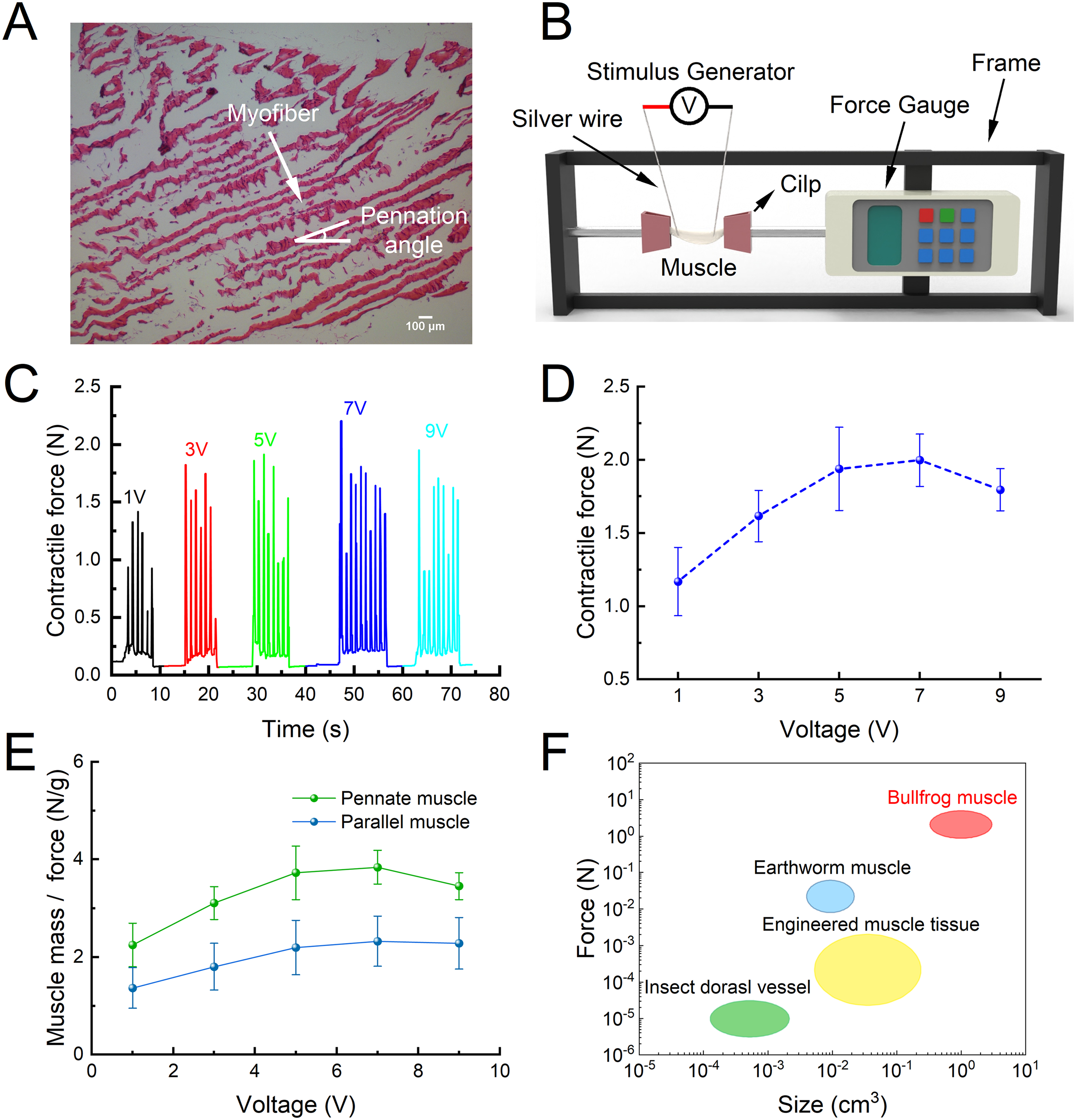
Structure and contractile force of the posterior triceps femoris muscle from the bullfrog.
We then constructed an experimental platform to analyze muscle contraction behaviors under different electrical stimuli (Fig. 3A). We applied two different electrical stimuli, pulsed electrical stimulation and square wave electrical stimulation, and the difference in waveforms between them is shown in Supplementary Fig. S3. Specifically, the duty cycle of pulsed electrical stimulation was only 1%, while the duty cycle of square wave electrical stimulation was 50%. First, we glued five green wooden pieces onto the muscle to divide it into four sections, allowing us to accurately and finely analyze the muscle contraction behavior based on the contraction parameters of different segments (Fig. 3B). In detail, we used our developed tracking software (Supplementary Fig. S4) to track the changes in the distance between round wooden pieces and the angle between different segments during muscle contraction and obtained corresponding strains (Δ) and angles (θ). Through a time series of muscle contractions under different electrical stimuli, we observed that the muscle produced twice contraction in different directions under square wave stimulation (muscle deflected to one side at 0.22 s and to the other side at 0.68 s) (Fig. 3Ci, Supplementary Movie S1), whereas only once contraction under pulse stimulation (muscle deflected to one side at 0.22 s) (Fig. 3Cii, Supplementary Movie S1). This result suggested that the muscle contraction behavior varies with different types of stimulus signals. Because of the difference in width between pulse wave signals and square wave signals, the number of times the electrical signal activates the muscle is very different, making a big difference in muscle contraction. Specifically, pulse signals have a duty cycle of only 1%. The activation of the muscle is more like a transient stimulus, so the muscle will only respond quickly once. Square wave signals have a 50% duty cycle. When the frequency of the signal is 1 Hz, the muscle responds once to a voltage rise in 0 s–0.5 s, and then again to a voltage fall in 0.5 s–1 s. This is why the tissue seems to be behaving erratically, with strain all over this period with square wave stimulation, while the contraction is cleaner with pulse signal stimulation.
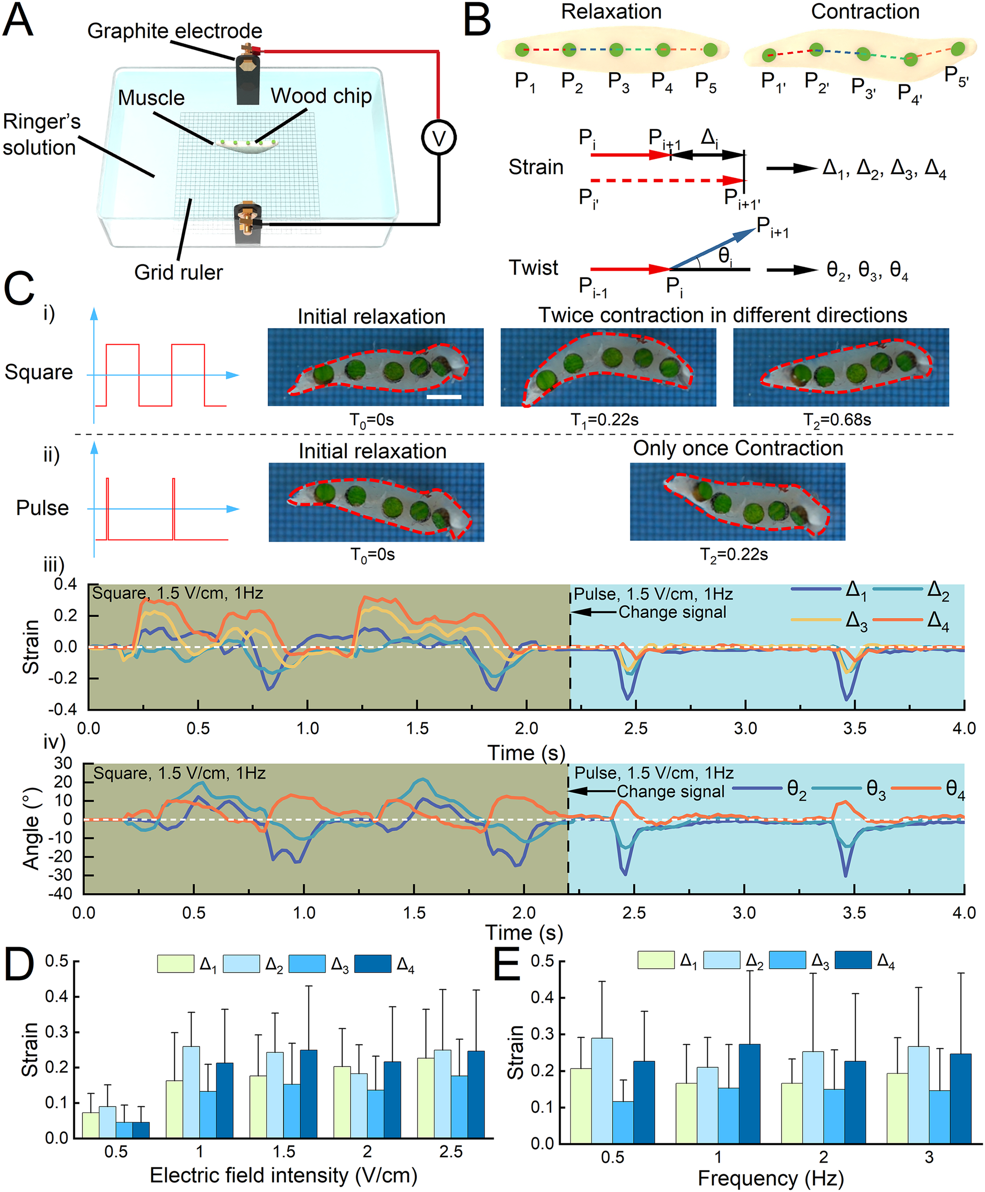
Contractile performance of the triceps femoris tissue under electrical stimulation.
Subsequently, by quantitative analysis of strain and angle (Fig. 3Ciii and iv), we found that the twice contraction of the muscle under square wave stimulation was not symmetrical, and there were significant differences in strain and angle. Next, we stimulated the muscle with a square wave of different electric field intensities and frequencies and analyzed the strain magnitude to determine the optimal stimulation parameters for the muscle in subsequent experiments. We found that the strain gradually increases with the stimulation intensity and the maximum contraction strain saturates to a constant value at 1.5 V/cm (Fig. 3D, Supplementary Movie S2). However, muscle strain did not change significantly at different electrical stimulation frequencies (Fig. 3E, Supplementary Movie S3). It is noteworthy that we observed the contraction of the tissues from 0.5 Hz to 2 Hz was a normal twitch. In contrast, at frequencies higher than 2 Hz, the contraction of the tissues changed to tetanus. Here, the electrical parameters (square, 1.5 V/cm, 1 Hz) were selected for muscle actuation to avoid tetanus generation and improve controllability and long-term activity. Through this part of the experiment, we found that the muscle demonstrated sensitive signal responsiveness and the ability of muscles to contract asymmetrically in two directions under square wave stimulation. Specifically, sensitive signal responsiveness refers to the ability of a muscle to respond quickly to an electrical stimulus signal and demonstrate different contractile behaviors depending on the waveform and parameters of the electrical stimulus signal.
Furthermore, to investigate the impact of electrical stimulation modes on muscle contraction behavior, we used a pair of silver electrodes to perform unilateral square wave stimulation (1.5 V/cm, 1 Hz) on the muscle and record the changes in the angle between the head-tail lines of muscle at the initial and final moments (Fig. 4A). We found through time series diagrams (Fig. 4B, Supplementary Movie S4) that the muscle turned in different directions according to the stimulation mode. In detail, when the electrode was located on the left side of the muscle for stimulation (0–7 s), the muscle turned right. Then we changed the position of the electrode (the right side) at 8 s. The muscle turned left (9–21 s). By analyzing muscle contraction behavior, we found that the reason for muscle turning was that the muscle was subjected to asymmetrical electrical stimulation, and the displacement of bidirectional contraction was different, resulting in a net displacement that caused the muscles to turn away from the electrodes. The turning speed was different due to the asymmetry of the muscle structure. The right turning speed was about 6.4°/s, and the left turning speed was about 3.0°/s (Fig. 4C). These results demonstrated that the distinctive directional contraction characteristic of the tissue under different electrical stimulation modes provided a turning control strategy for robotic steering maneuverability. And we believe that this steering control method can be applied to most kinds of skeletal muscle cells and tissues.
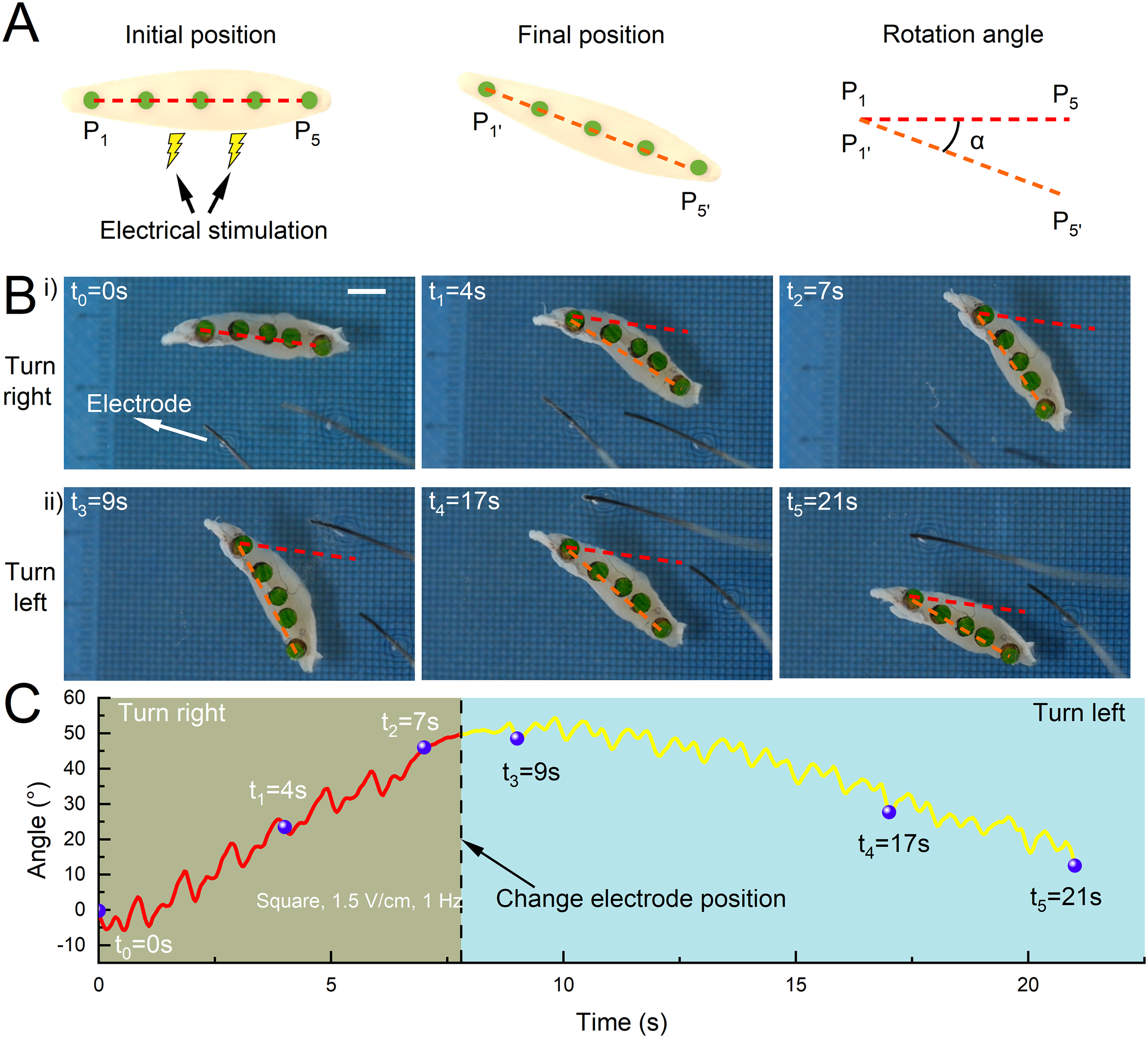
Muscle turning ability under selective unilateral stimulation.
Motion performance of the robots actuated by triceps femoris tissue
We initially designed a swimming robot based on the characteristics of muscle swing contraction. This robot consists of three parts: a muscle, a wooden plate for buoyancy in the head, and a plastic plate for tail swing. However, we found that the swimming robot did not move forward but instead exhibited rotational motion. We believe that there are two reasons for the failure. First, the asymmetry of friction between the head and tail structures of the robot is insufficient, preventing the robot from generating net forward propulsion. Second, bidirectional muscle contractions are not completely symmetrical (Supplementary Movie S1). Consequently, the propulsive forces generated on either side of the tail section of our fish-inspired robot are unequal. This thrust imbalance creates a torque deflection, causing the robot to rotate (Supplementary Movie S5). In addition, we incidentally found that when the tail of the swimming robot touched the bottom of the container, the motion changed significantly and the robot moved forward (Supplementary Movie S6). To further determine the possibility of forward motion of the robot, we replaced the tail of the swimming robot with a counterweighted foot. The results showed that the robot could move forward stably (Supplementary Movie S7). However, this foot structure could not take full advantage of the muscle swing contraction, so we optimized the design of the foot. Inspired by bipedal walking animals, we designed a bionic foot for the robot. The curved detailing of the foot is derived from our group’s previous foot design, which shows good locomotor capabilities. 5 Then we optimized the robot’s head, which was designed as a streamlined hollow head. The hollow head of the robot serves two main functions: the first is to provide friction that is different from that of the foot, and the second is to give buoyancy to the muscle to maintain the robot’s posture. Without the hollow head, the muscle would fall to the bottom of the container and affect the robot’s movement. Because the hollow head of the robot floats in the water without contacting the container, the coefficient of friction between the hollow head and the water is significantly smaller than the coefficient of friction between the foot of the robot and the bottom of the container during the movement. We measured the coefficient of friction between the robot’s foot and the bottom of the container to be 0.466 before we started the experiment.
In short, we designed a crawling robot that contains three parts: muscles, a hollow head and feet. The thinner end of the muscle is fixed to the hollow head, while the thicker end of the muscle is fixed to the feet. The robot is then placed in a container filled with Ringer’s solution. Like muscle testing, we performed bilateral square wave electrical stimulation (square, 1.5 V/cm, 1 Hz) on the crawler (Fig. 5Ai). The motion video (Supplementary Movie S8) showed that the robot can achieve directed forward motion and that the feet with the silver wire are in contact with the ground at all times during the motion. The reason for the robot’s forward motion is that there is a difference in head and foot friction, with head friction being less than foot friction. Specifically, when the muscles contract, the robot’s head retracts and the foot moves forward. In contrast, when the muscles relax, the robot takes the foot, which has more friction, as an anchor point and translates the muscle relaxation into a forward displacement of the head, resulting in an overall forward movement of the robot. From this, we know the macro mechanism that allows the robot to move forward.
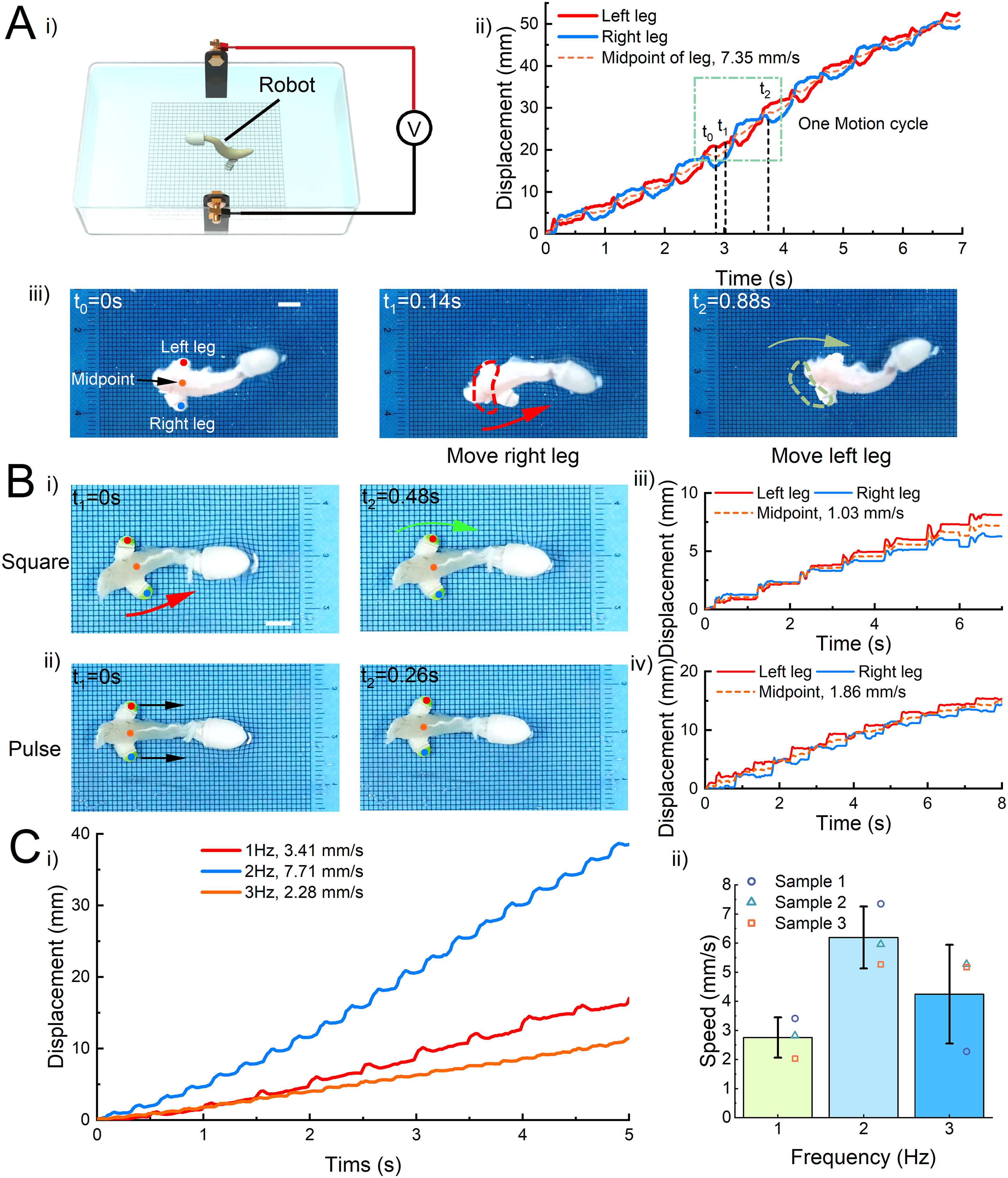
Robot forward ability under bilateral stimulation.
We used the crawler’s left and right feet as marker points for tracking movements to specifically analyze the robot’s more detailed motion mechanisms. Then, the coordinates of the left and right feet points were combined to obtain the midpoint coordinates. In this way, we obtained the motion trajectories and displacement time curves of the crawler’s left foot, right foot, and midpoint (Fig. 5Aii). We found that there is a delay between the left foot curve and the right foot curve, resulting in a sequential gait-like motion. Furthermore, based on the midpoint curve, the average motion speed of the sample crawler is 7.35 mm/s. The timing series diagrams of one motion cycle (Fig. 5Aiii) showed that the bidirectional muscle contraction transforms into the crawler’s alternating left and right forward walking motion. In detail, the crawler remained stationary at 0 s and then applied square wave electrical stimulation. At 0.14 s, the muscle contracts and swings to the right, and the center of gravity of the muscle is shifted to the left foot. An asymmetrical pressure is generated in the robot’s feet, with the pressure in the left foot being greater than that in the right foot. Therefore, the right foot will rotate forward with the left foot as the anchor point under the driving force of muscle contraction. Then, at 0.88 s, the muscle contracted and swung to the left, the right foot pressure is greater than the left foot, and the left foot rotates forward using the right foot as an anchor point. In this way, the left and right feet alternated and moved forward, achieving a complete gait cycle of crawler forward motion. The step size of the crawler was approximately 6–8 mm. In addition, because of the asymmetry of the bidirectional contraction of the muscle itself, the overall trajectory of the robot is not a strictly straight line but an oblique straight line with a deviation angle range of about 4.85 ± 1.86°.
Then, to explore the differences in crawler movement under pulse and square wave stimulation, we applied two types of electrical stimulation (square/pulse, 1.5 V/cm, 1 Hz) to the same crawler and observed its gait and movement speed. By comparing the keyframe timing diagrams of the robot motion (Fig. 5Bi and ii, Supplementary Movie S9), we found that the crawler didn’t move forward alternately with their left and right feet under pulse stimulation, but rather moved forward as a whole, like jumping. More intuitively, we can see from the displacement time curves of the crawler motion under pulse stimulation that the crawler’s left and right feet move forward synchronously without delay. Moreover, the motion speed of this sample crawler under square wave stimulation is 1.86 mm/s, while the speed of the robot under pulse electrical stimulation is only 1.03 mm/s (Fig. 5Biii and iv). In other words, the motion speed of the crawler under pulse stimulation is only 55% of that under square wave stimulation. This result indicated that the gait of bipedal walking activated by square wave stimulation can improve the motion speed of the crawler.
Stimulation frequency is a key parameter that affects the speed of crawler movement. Therefore, we changed the frequency (1, 2, and 3 Hz) of square wave electrical stimulation and obtained the displacement curves of the crawler at different frequencies (Supplementary Movie S10). From the motion tracking results of this sample crawler, the crawler has a speed of 3.41 mm/s at 1 Hz, 7.71 mm/s at 2 Hz, and 2.28 mm/s at 3 Hz (Fig. 5Ci). The crawler moved the fastest at a frequency of 2 Hz electrical stimulation. Based on the previous experimental results of muscle contraction and analysis of crawler motion videos, we found that the muscle normally twitches below 2 Hz, and the movement frequency of the crawler increases with the increase of stimulation frequency, thereby improving the movement speed. The contraction of the muscle began to incomplete tetanus over 2 Hz. At this time, the muscles briefly relaxed after the contraction, but before returning to normal relaxation, they began the next contraction. This situation led to a significant reduction in the crawler’s step size, which reduced the crawler’s motion speed. The average speed of the crawler was 2.75 mm/s at 1 Hz, 6.19 mm/s at 2 Hz, and 4.24 mm/s at 3 Hz (Fig. 5Cii).
Then we evaluated the crawler’s turning ability based on the control strategy of unilateral electrical stimulation mode. First, we sequentially performed electrical stimulation on the left and right sides of the crawler, and the position and angle changes of the crawler’s head-tail lines were tracked. We found that the muscle contracted and turned with the foot away from the electrode as the fulcrum (Fig. 6A, Supplementary Movie S11). Therefore, when the electrode stimulation was on the left (right) side of the muscle, the crawler would turn right (left). As shown in this sample crawler, the crawler had a left turn speed of 6.37°/s (Fig. 6Bi) and a right turn speed of 12.75°/s (Fig. 6Bii). This speed difference was highly relevant to the tissue’s unsymmetrical structure and contractile performance. The average left turning speed of the crawler was 14.77°/s, and the average right turning speed was 9.55°/s (Fig. 6C). The high angular velocity displayed exactly superior steering maneuverability of the crawlers. Moreover, by comparison with the original location of the crawler, we can find that the turning radius was close to the leg length (∼12 mm), indicating the agile locomotion capacity of the crawler. It is worth noting that the robot’s ability to turn is greatly disturbed by manual operation, which is less controllable. A better alternative would be to construct an electric field device that enables precise control of the robot’s turning remotely by controlling changes in the electric field.
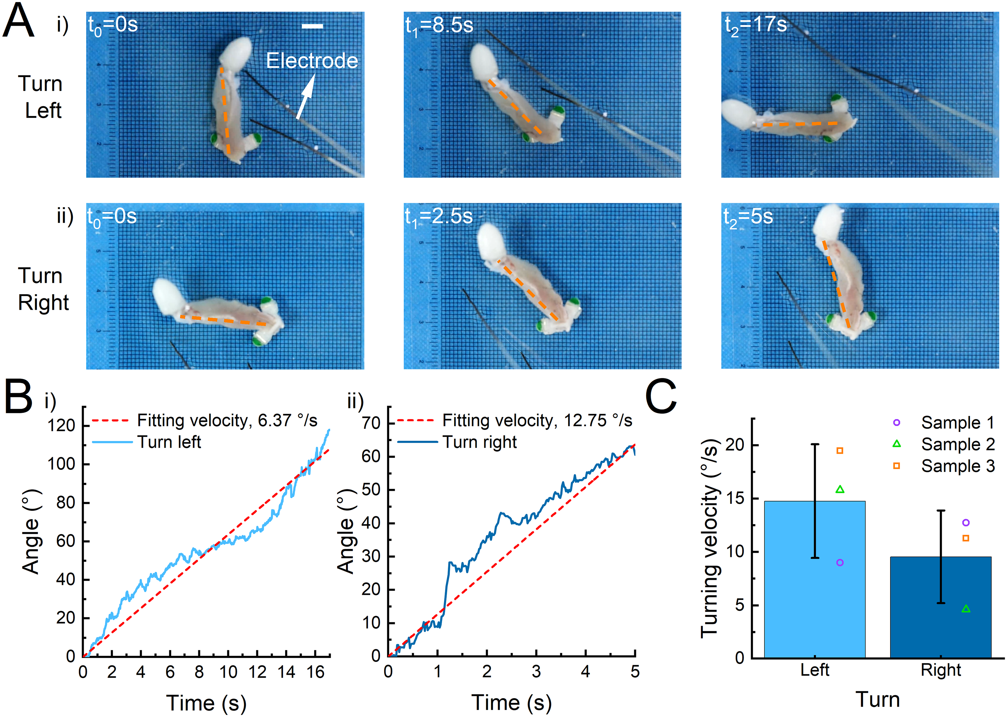
Robot turning ability under selective unilateral stimulation.
Finally, to further validate the crawler’s ability to maneuver, we challenged it to traverse an obstacle course. We constructed an area with multiple obstacles using wooden boards and a chamber (Fig. 7A). Then, we placed the crawler on the lower right side of the obstacle area. We held a silver wire electrode and performed square wave electrical stimulation guidance (square, 1.5 V/cm, 2 Hz) on the crawler. The crawler completed a clockwise turn through obstacles by changing the electrical stimulation mode for about 50 s. The forward and turning stimulation methods of the crawler were the same as before. By tracking the midpoint of the crawler’s foot, we obtained a displacement time curve of the crawler (Fig. 7B). The average speed of the crawler could reach ∼3.17 mm/s over ∼164 mm. In detail, the crawler moved forward in 0–5 s, turned left in 6–11 s, moved forward in 12–20 s, turned left in 21–33 s, moved forward in 34–42 s, turned left in 43–47 s, and moved forward in 48–50 s. Here, we presented a time trajectory diagram of the overall motion of the crawler (Fig. 7C, Supplementary Movie S12).
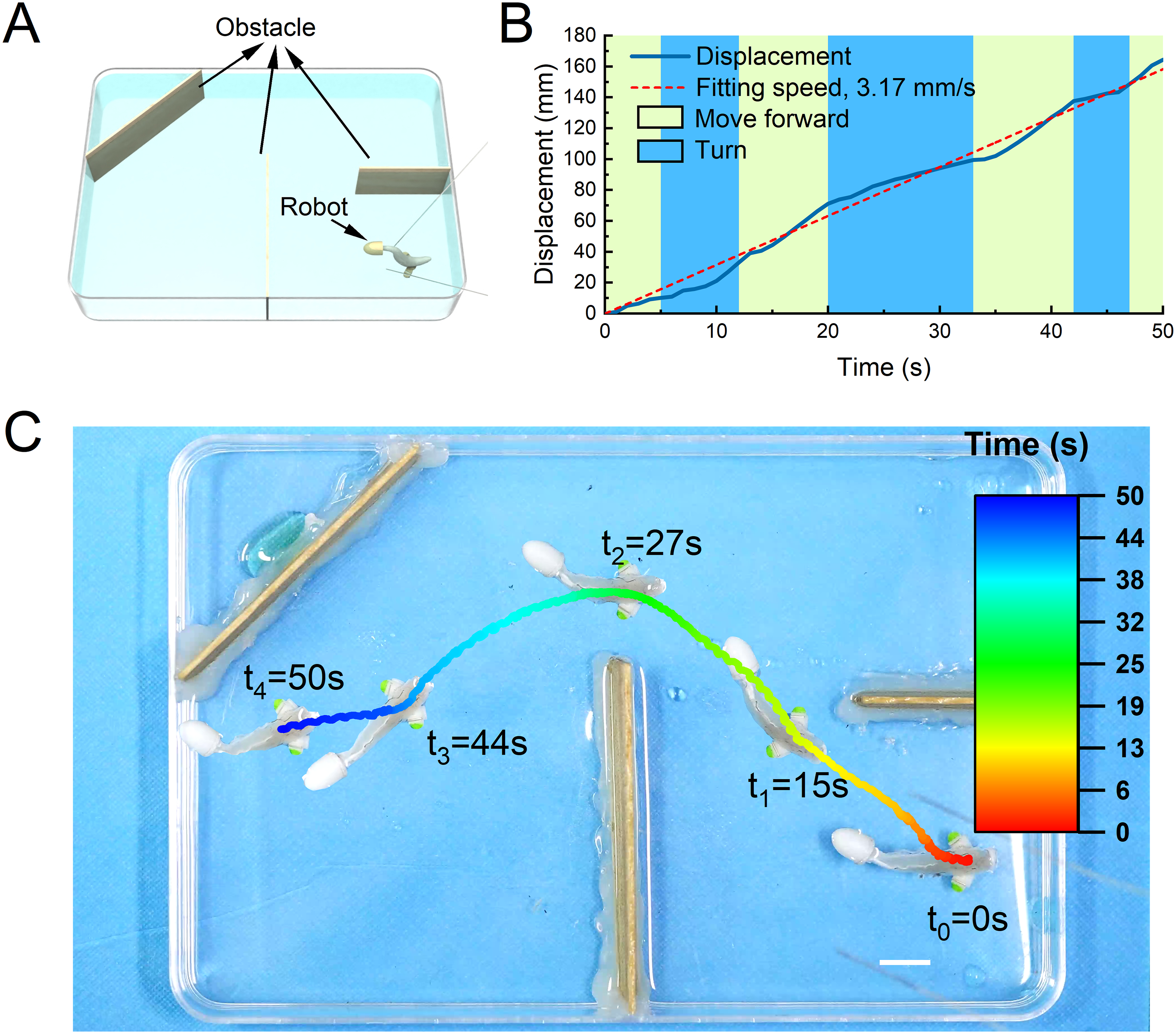
The comprehensive motion ability of the robot crossing multiple obstacles area under electrical stimulation.
Discussion
In this study, we developed a biomimetic crawler actuated by triceps femoris tissue from a bullfrog. The crawler can alternate left and right feet like a bipedal animal to achieve fast forward movement (average speed: ∼6.19 mm/s; maximum speed: ∼7.35 mm/s) and flexible turning movement (14.77°/s and 9.55°/s for left and right turning speed, respectively). Our crawler outperformed existing locomotive biohybrid crawling robots actuated by cardiomyocytes,12,31–33 insect dorsal vessel tissues, 27 and skeletal muscles13–17,19,26,34,35 in terms of motion speed (∼11.25 body-length/min, Fig. 8A). For instance, Feinburg et al. constructed a myocardial film, which was folded to obtain a crawling robot with a movement speed of 8 mm/min (∼2.7 body-length/min). Sun et al. were inspired by the crawling mechanism of caterpillars and constructed a myocardium-driven crawling robot, which moved at a speed of 20 μm/s. Zhang et al. were inspired by musculoskeletal structures and developed a bionic bipedal steerable crawling robot with a crawling speed of 80 μm/s. Kim et al. constructed a crawling robot that can be remotely controlled at speeds of 0.83 mm/s, which is also equipped with a steering function. Akiyama et al. constructed a novel autonomously contracting crawling robot using insect dorsal vascular tissue that can reach speeds up to 257 μm/s. Moreover, our crawler also had a simpler turning structure (compared with a robot structure driven by multiple muscles), the fastest turning speed (14.77°/s and 9.55°/s for left and right turning speed respectively), and a smaller turning radius (Fig. 8B).
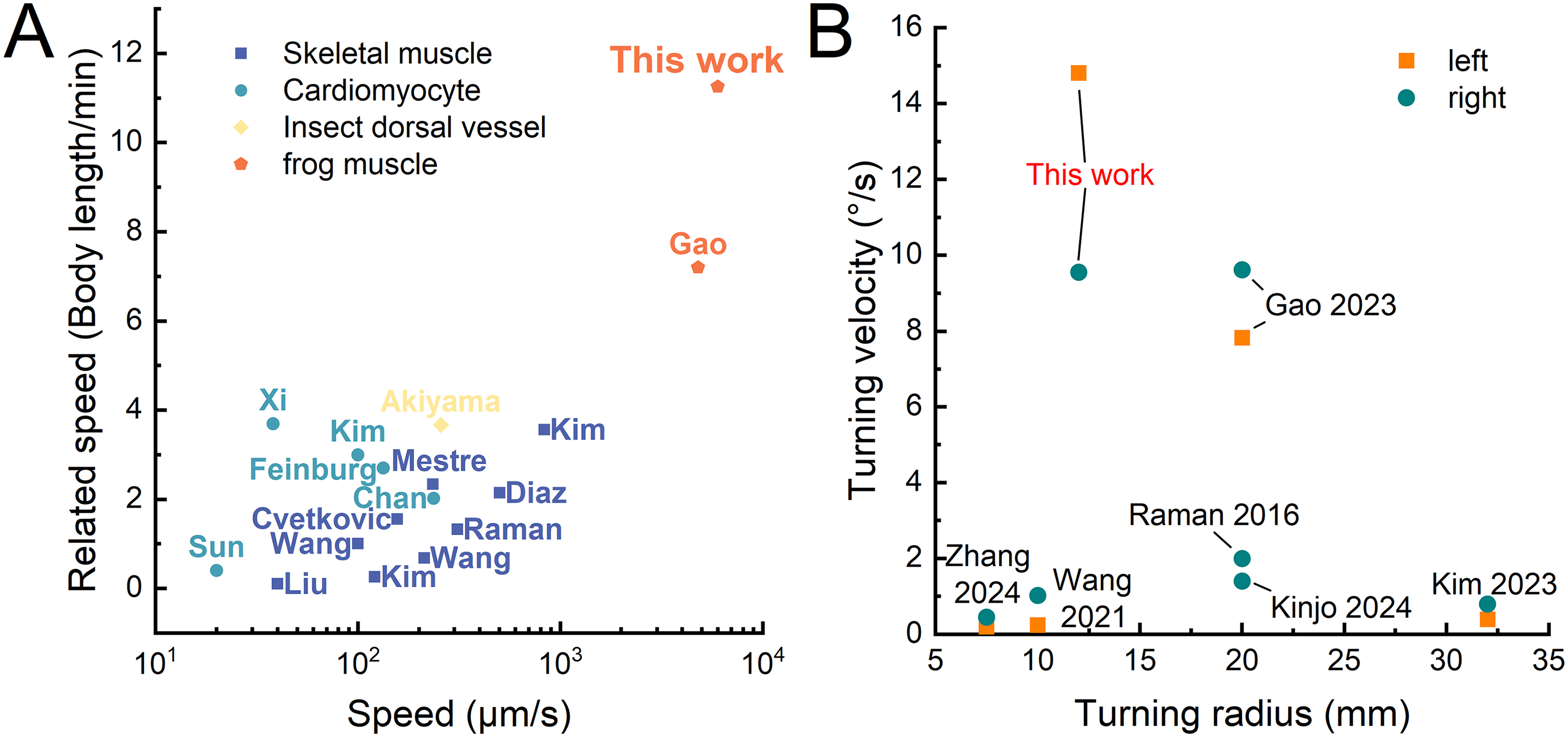
Comparison of actuation performance for biohybrid crawling robots.
There are three main reasons for the crawler’s superior performance: powerful muscle tissue, new stimulus control methods, and matched mechanical design. First, we used a frog muscle as the driving material. Frogs are famous for their explosive jumping movements in nature, and their muscle tissues have excellent performance. 36 The muscles of the hind limbs, which are responsible for jumping, are particularly well-developed. The triceps femoris is the largest muscle in the frog’s thigh (accounting for about 2% of the body weight), and it is the key part of the hind limb muscles for force generation. Meanwhile, it plays an extremely important role in jumping for the anterior extension and adduction of the calf. 37 Staining of this muscle showed that the myofibers exhibited the structural feature of a feathery arrangement. It has been demonstrated that the contractile force produced by a muscle is determined by the physiological cross-sectional area. 38 The larger the physiological cross-sectional area of a muscle, the greater the muscle force. The pennate structure allows the physiological cross-sectional area of the pennate muscle to be larger than that of the parallel muscle for the same muscle volume, which allows the pennate muscle to produce greater force. 39 Therefore, we used this muscle as an actuator to ensure ample power for the crawler.
Second, we used a new stimulus control method that allowed the muscle to exhibit a new mode of bidirectional swing contraction in response to square-wave stimulation. Previously, researchers usually stimulated muscle tissue only with pulses in the range of 1–50 ms in an attempt to match the effect of neuronal stimulation, while neglecting the study of stimulation with other signals. 40 Our study used a square wave signal with a duty cycle of 50% instead of the pulse signal with a duty cycle of 1% commonly used in previous studies. These two signals cause very different muscle contraction modes. Specifically, in a stimulation cycle, the pulse signal causes the muscle to produce a single unidirectional contraction, while the square wave signal causes the muscle to produce two bidirectional contractions. Our study showed that square wave stimulation is more effective for muscle stimulation compared with pulse stimulation of the same amplitude and frequency. Due to the difference in pulse width, the effective voltage of the square wave was greater than that of the pulse, resulting in a fuller muscle contraction and a greater swing amplitude. Furthermore, we believe that muscles had different contractile responses to the rising and falling edges of the signal. Because the interval between the rising and falling edges of the pulse signal was too short, the muscles with low-frequency response characteristics cannot adequately respond to such a rapid voltage change and perform contraction behavior accordingly. In contrast, the interval between the rising and falling edges of the square wave signal was long enough to allow the muscle to respond adequately to the voltage change and show two contraction behaviors with different directions within one stimulation cycle. Therefore, under square wave stimulation, the full, fast, and bidirectional contraction behavior of the muscles allowed the crawler to achieve fast bipedal forward movement.
Finally, we designed a novel mechanical body structure that matches the muscle contraction characteristics. Most of the traditional crawling robot structures were based on the classical structure of the skeletal muscle system and its iterative upgrading, with the same basic motion principle and the same problems.13,15,26 The motion principle of the structure was similar to that of an inchworm, which realized directional motion through front and rear feet with different friction coefficients. We believe that there were two key problems with this structure: first, the difference in friction coefficient between the front and rear legs was realized by changing the length and contact areas of the legs, and the difference in friction coefficient is limited. Second, the front and rear feet of the crawler were in contact with the ground over a large area, which resulted in a large overall resistance to motion. The above problems limited the motion speed of the crawler. In response to the problems of the traditional robot structure, and combined with the new bidirectional muscle contraction characteristics, we matched the design of a new mechanical body structure and movement principle, so that the crawler can be like a bipedal animal for foot alternation and forward movement. The bipedal motion itself has natural advantages in terms of energy consumption and environmental adaptability, which lays a theoretical foundation for the rapid motion of robots. 41
In addition, our robot is designed for underwater environmental exploration. In the fields of near-bottom sampling or observation, crawling robots demonstrate superior stability and operational accuracy. This advantage stems from their direct contact with the seabed, which minimizes disturbance from ambient currents—a critical limitation for swimming robots that rely on floating, paddling, or jet propulsion. We hope to apply this small, low-cost (about $1 per robot), low-drive-voltage, environmentally friendly robot cluster for underwater environmental exploration and detection in uncharted areas. Unfortunately, our robot has not yet been successfully applied, and there are still many problems to overcome. To realize the real application, we believe that we still need to work on at least two aspects. The first is to integrate a small remote-control system that will allow the robot to be operated remotely underwater. The second is to explore muscle protection methods to keep the robot free from bacterial contamination, thus extending its lifespan. We will continue our research toward these two areas in the future.
We believe that the results provide novel and valuable references for the development of soft robots driven by muscle tissues and pave the way to fulfill lifelike motions to break through limitations in conventional biohybrid robots. Specifically, many movements in nature are dominated by swinging and contracting patterns, especially fish swimming. Based on the above results, we may develop more diverse robot models, such as fish-like swimming robots.
However, our research still has two main limitations. First, using natural bullfrog muscles has limitations in terms of robot structure and size, resulting in low design degrees of freedom. The second issue is that the electrical stimulation device was not integrated into the robot, and remote control was not achieved. In response to the above issues, our idea is to develop extraction and cultivation techniques for primary bullfrog skeletal muscle cells, and further integrate wireless electrical control technology into robots to make them more potential for application.
Authors’ Contributions
L.G.: Supervision, conceptualization, writing—review and editing, project administration, and funding acquisition. W.W.: Investigation, methodology, visualization, and writing—original draft preparation. W.C.: Investigation and methodology. Z.L.: Visualization. X.X.: Investigation. L.L.: Writing—review and editing. Q.L.: Investigation, writing—review and editing. Y.W.: Writing—review and editing. J.F.: Visualization. J.H.: Supervision. D.L.: Supervision.
Footnotes
Author Disclosure Statement
No competing financial interests exist.
Funding Information
This work was supported in part by the National Natural Science Foundation of China (grant number 52175276), the Program for Innovation Team of Shaanxi Province (2023-CX-TD-17).
Supplemental Material
Supplemental Material
Supplemental Material
Supplemental Material
Supplemental Material
Supplemental Material
Supplemental Material
Supplemental Material
Supplemental Material
Supplemental Material
Supplemental Material
Supplemental Material
Supplemental Material
References
Supplementary Material
Please find the following supplemental material available below.
For Open Access articles published under a Creative Commons License, all supplemental material carries the same license as the article it is associated with.
For non-Open Access articles published, all supplemental material carries a non-exclusive license, and permission requests for re-use of supplemental material or any part of supplemental material shall be sent directly to the copyright owner as specified in the copyright notice associated with the article.