



Abstract
Soft growing robots, commonly referred to as vine robots, have demonstrated a remarkable ability to interact safely and robustly with unstructured and dynamic environments. It is therefore natural to exploit contact with the environment for planning and design optimization tasks. Previous research has focused on planning under contact for passively deforming robots with preformed bends. However, adding active steering to these soft growing robots is necessary for successful navigation in more complex environments. To this end, we develop a unified modeling framework that integrates vine robot growth, bending, actuation, and obstacle contact. We extend the beam moment model to include the effects of actuation on kinematics under growth and then use these models to develop a fast parallel simulation framework. We validate our model and simulator with real robot experiments. To showcase the capabilities of our framework, we apply our model in a design optimization task to find designs for vine robots navigating through cluttered environments, identifying designs that minimize the number of required actuators by exploiting environmental contacts. We show the robustness of the designs to environmental and manufacturing uncertainties. Finally, we fabricate an optimized design and successfully deploy it in an obstacle-rich environment.
Introduction
Soft growing robots, also known as vine robots, are a class of continuum robots that extend from the tip by pressure-driven eversion. 1 Since growth isolates the robot from the environment, vine robots have shown significant beneficial behaviors in tasks with natural pathways to follow, such as medical procedures,2–4 especially for colonoscopies and endoscopies,5–7 pipe inspection, 8 and archaeology. 9 These behaviors arise from the passive buckling of thin inflated tubes,10,11 a challenging feature to accurately model.
Multiple works have examined kinematic models to predict and use this passive deformation.12,13 However, the heuristic models in these works have been limited to purely passive behavior, primarily due to the increased difficulty of modeling the effects of active steering. Other works have also addressed the general simulation of vine robot growth with at most some preformed deformations, including fast, kinematic-only models 14 and dynamic simulations.15,16 While slow and accurate Finite Element Method (FEM) simulators 17 have been used to model actuated vine robots, 18 these are inefficient for downstream tasks such as planning, control, and design that require high-throughput simulation. Recent work has addressed fast parallel simulation of these robots that accurately captures the bending and buckling behavior intrinsic to vine robots. 19 However, no simulation framework has addressed efficient modeling of actuated vine robots under contact forces.
While previous studies have captured the obstacle interactions of vine robots under passive deformation, this work achieves the integration of all key capabilities, including growth, pneumatic actuation, beam mechanics, and environmental contact. In this work, we provide for the first time the tools to design, model, control, and plan actuation for vine robots in contact-rich, complex environments. To validate our framework, we deploy the optimized designs in real environments and compare the performance with simulated predictions. Our major contributions include:
In summary, our work presents a unified computational framework to optimize the design of vine robots. These advances enable the implementation of simulation tools to deploy optimized designs in real, cluttered environments. We release our simulator and design optimization tool as open source: https://github.com/CoMMALab/ActVineSimPy.
Related Work
The flexible, yet inextensible material used in vine robots necessitates the use of novel approaches for modeling and simulation of vine robot behavior. While early modeling focused primarily on describing the growth, 22 first-principles models for vine robot buckling have been built on inflated thin-shelled beam models.10,23 Discrete buckling models, which predict restoring moment independent of bend angle,11,24 led to kinematic models for contact-induced bending, 13 tip localization, 25 and obstacle mapping. 12 Recent work has further strengthened this model by considering partial buckling. 21
For distributed surface wrinkling, these constant moment models are not as accurate, so heuristic models have been developed instead, using experimental parameter fitting to create kinematic models, 26 or geometrically relating surface strain to resulting general curves.27,28 The geometric mappings are generally limited to quasi-static behaviors, though data-driven approaches with Koopman operators have shown that dynamic behaviors can also be empirically modeled. 29 While combined system models have been primarily heuristic, some first-principles actuator models have been developed for series pneumatic artificial muscles (sPAMs) 26 and a range of other common and vine robot-specific actuators. 30
While actuator-beam models describe free-space actuated vine robots, incorporating contact with the environment is challenging. Finite element models built on frameworks like SOFA 17 have been used to successfully model vine robots.16,18,31,32 However, these approaches are computationally expensive and ill-suited for real-time, at-scale simulation. Other work has simplified the simulations to rigid body models, either using minimal coordinates through virtual joint angles 33 or maximal coordinates with poses of frames in a global reference with implicit constraints. 15 Previous work has proposed more realistic models for computing strain that respect geometric design parameters28,34 and has made these scalable using GPU-accelerated computation frameworks. 19 Overall, our work fills a gap for efficient models that generalize to external and internal forces.
Our design optimization approach is built upon sampling-based kinodynamic planning (SBKP),35–37 which addresses the general problem of finding a sequence of controls that, when applied to a robot, achieves a goal state. Unlike previous works that use planning to design a vine robot 38 , we are given only a black-box forward dynamic simulation that captures the vine robot evolution given actuation and environment interactions. Some planners, such as Kinodynamic-RRT* for linear dynamics, 39 arbitrary kinodynamic planning in combination with the AO-X meta algorithm, 40 and Stable Sparse RRT (SST), 37 provide asymptotic optimality guarantees, but with no guarantee on when high-quality solutions will be found. Thus, in practice, accelerating the speed of dynamic simulation, the bottleneck of SBKPs, helps them find better solutions faster. Recent work such as Kino-PAX 41 has focused on highly parallel implementations to address these computational challenges. Our approach also leverages the large-scale batch GPU computation of our proposed simulator to improve performance.
Modeling of Combined Actuation and Growth
Accurately modeling actuated soft growing robots under environmental contact presents a challenge due to the nonlinear coupling between actuator force and displacement, beam stiffness or restoring moment, and contact forces. While an actuated robot deployed in free space can be modeled heuristically as one or more constant curvature segments with radius of curvature inversely proportional to actuator pressure, 26 and the path of an unactuated vine robot under environmental contact can be robustly predicted based on the visibility graph of the obstacles, 14 these heuristic models do not obviously or easily combine. To address this complexity, we develop a unified modeling approach that builds on analytical models of each component separately and then discretizes the vine robot along its length to locally capture the effects of contact and actuation. With this model, the vine robot’s dynamics can be simulated in cluttered environments, where contact interactions significantly influence robot behavior and thus can be exploited for improved navigation performance. In this section, we present each component model separately and then discuss the method to combine the models to accurately predict both actuation and contact with the environment.
Serial pneumatic artificial muscles
We employ serial pneumatic artificial muscles (sPAMs) to apply distributed actuation along the robot body. A sPAM can be fabricated using a pliable thin-film tube, which has an inflated radius

To make an actuator component model, we build upon the refined sPAM model in study by Wang and Blumenschein,
34
which adapts the ideal PPAM (Pleated Pneumatic Artificial Muscle) model in study by Daerden.
42
The ideal PPAM model does not account for the saturation based on the tube radius, only predicting the cross-section profile, which maintains the material length and maximizes volume. The improved sPAM model incorporates actuator saturation by moving the saturated length to shrink the effective length of the actuator when predicting the force–strain output. For a given set of actuator design parameters and pressure inputs:




Here,
Wrinkling-based restoring moment model
The body of the vine robot is made of a pressurized thin-film tube, which we can treat as an inflated beam. An inflated beam model developed by Comer and Levy
10
demonstrates that the restoring moment of a bent inflated beam increases with surface wrinkling development at bending locations. Previous implementations of this model have focused on the maximum restoring moment when the surface is fully wrinkled, especially in works that discuss the buckling of the vine robot under environmental forces.
13
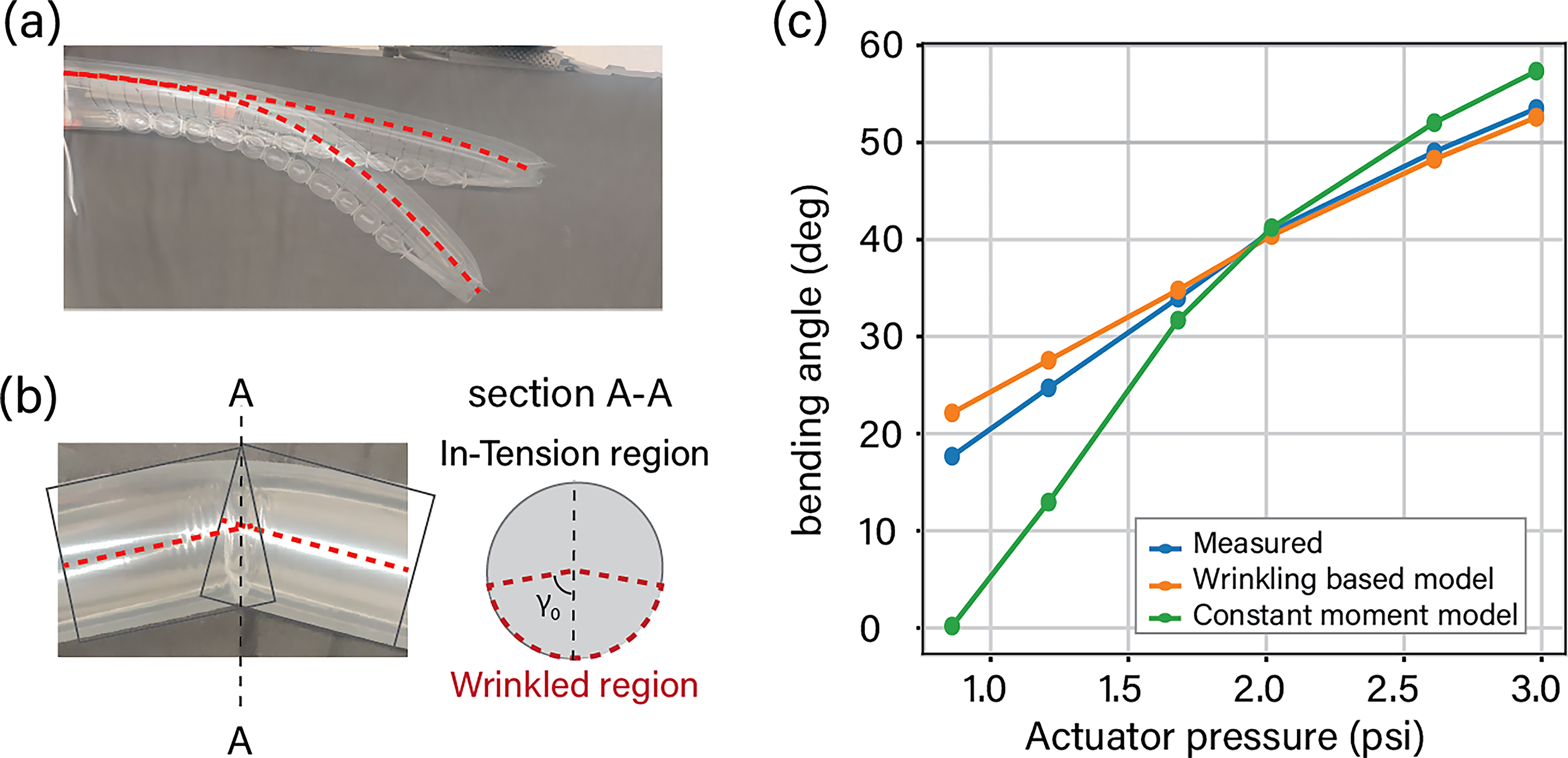
However, for small deflection angles (≲10 degrees), like those seen in steering (Fig. 2a), this significantly overestimates the restoring moment. A wrinkling-based model described in study by Chen
19
captures this angle-to-moment relationship by introducing a critical surface strain


Here,
Combined actuation and contact model
To combine the component models, we can recognize that the moments exerted by the sPAMs and by the bending of the vine robot segment should balance in free space and combine to produce a net restoring moment under dynamic conditions. Without external contact, this equilibrium relationship enables the determination of both the strain produced in the vine segment and the radius of curvature in free space. Compared with previous approaches, the wrinkling-based model improves the accuracy of curvature determination, as shown in Figure 2c.
For developing the forward dynamics simulation that includes contact with the environment, the vine robot is discretized into rigid, serially connected segments. This allows the bending behavior of each segment to be considered separately. The segments have a length of
If the relative bending angle between any two consecutive segments of the vine robot is


Here, the restoring moment of the vine robot segment
Simulation of Actuation and Growth
Although the individual bending, growth, and contact behaviors are well defined, producing a realistic simulation requires unifying these forces into a single forward function. We combine these forces in a cost-minimization problem, which we use to solve for the next state with a position-based dynamics (PBD) 43 simulation method, which has shown success for rigid and soft body simulations alike. 44 The pipeline leverages GPU-accelerated batch processing to achieve the throughput requirements necessary for effective design optimization in complex environments. Algorithm 1 details the single simulation step that updates the vine robot position forward in time. This step essentially combines the effects of vine robot growth, bending, actuation, and obstacle contact to generate the next state of the vine robot.
Position-Based dynamic simulation
As described in Sec. 3.3, we chose to discretize the vine into a chain of bodies to produce a finite parameterization. We aim to find the dynamics

Equation (4) is highly nonlinear, and the relative magnitudes of each force can change rapidly. We use a penalty-based gradient method, which iteratively searches for the minimization of Eq. (4). We compute gradients using JAX autodifferentiation 45 and found 50 steps to be sufficient for convergence in all environments. The details of the implementation are presented in Algorithm 1.
1:
neural surrogate parameters
2: Initial vine state:
3:
4: Actuator force
5:
6:
7: Restoring moment
8: Total moment
9: Optimization Objective:
10: Gradient:
11: Gradient descent step:
12:
13:
Actuator design synthesis
Although it is desirable to parameterize actuators along the vine in terms of their produced turning angle
To resolve redundancies, we impose a cost function that favors higher pressure
Neural surrogate
As detailed in Sec. 4.2, actuator design parameter generation requires precise solutions to the sPAM model in Eq. (1). While numerical methods provide reasonable performance for individual solutions (requiring only milliseconds), we wish to use our actuator model in a design optimization task, which demands hundreds of thousands of simulation steps, corresponding to millions of individual sPAM model evaluations. In this high-throughput regime, numerical methods become computationally prohibitive. We instead approximate the sPAM model using a neural network surrogate. Analysis of the function reveals smooth and monotonic behavior of the output with respect to input parameters. The absence of high-frequency features and the single-mode nature of the function make accurate approximation by a neural surrogate possible, as such networks excel at fitting smooth, well-behaved data. Furthermore, neural networks can be evaluated efficiently in parallel.
The input parameters for the neural surrogate are sPAM actuator strain ϵ and actuator length
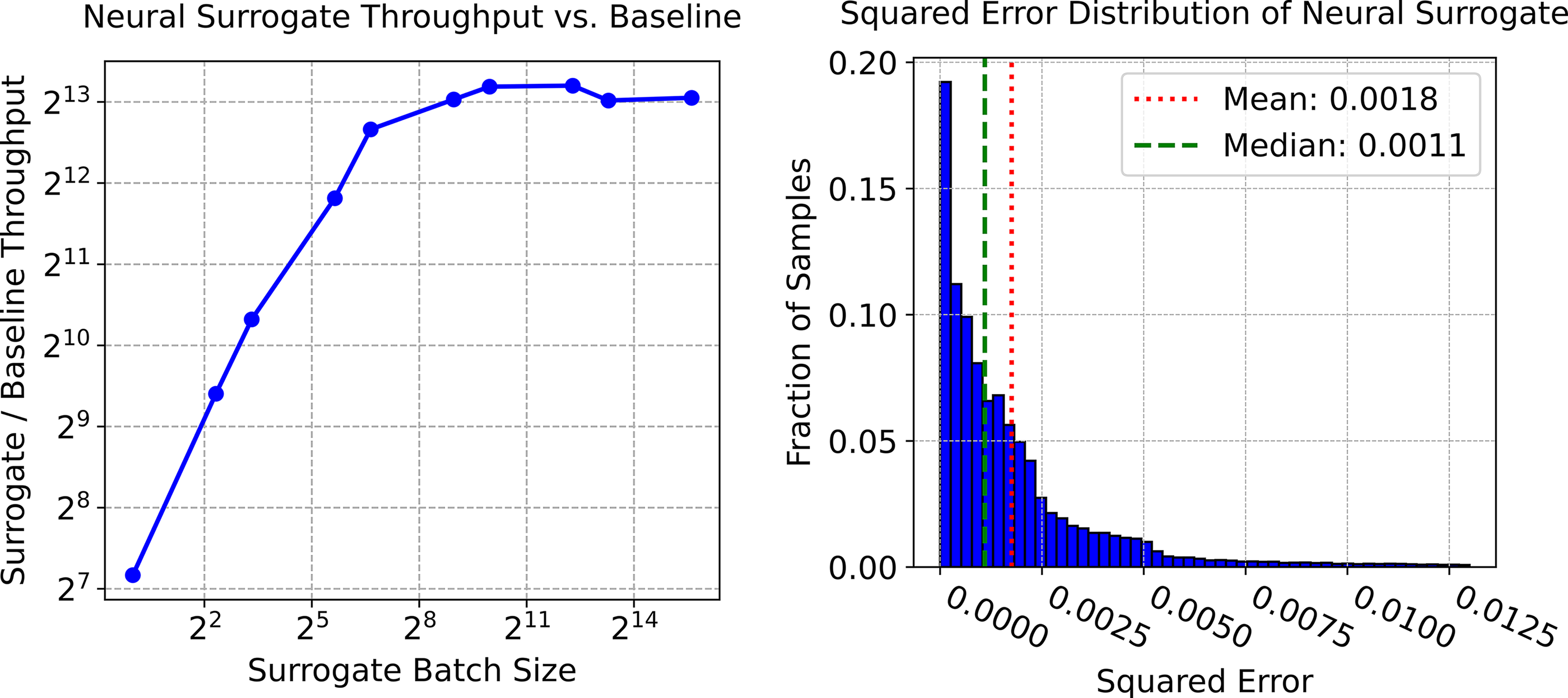
Left: The neural surrogate demonstrates a major speedup over the baseline unbatched method, especially as the batch size increases. Batched GPU processing can greatly accelerate parallelizable simulation tasks. Right: Distribution of neural surrogate squared error as compared with ground truth numeric method. We uniformly sampled 40,000 values over the surrogate’s input space and normalized the outputs.
Long-Horizon Design Optimization
In contact-rich environment navigation problems, contacts, nonlinear bending mechanics, and growth dynamics jointly determine vine behavior. Analytical or inverse numerical solutions for vine design under these coupled effects are either intractable or computationally challenging, necessitating approaches that use forward simulation. We formulate the design optimization problem for soft growing robots as a sampling-based kinodynamic planning (SBKP) problem. 36 SBKPs provide a framework for solving problems that can only be explored with forward dynamic simulation—in our problem, we simulate the vine robot under varying actuator design parameters and propagate the vine robot forward in time by simulating constant growth with sampled actuator designs.
Specifically, we use a modification to the Stable Sparse RRT* (SST*)
37
algorithm, which provides asymptotic near-optimality guarantees for finding dynamic paths between points given a cost. That is, as the number of samples drawn goes to infinity, the cost of the solution converges to
We modify SST* to make use of the simulation framework from Sec. 4 to provide batch simulation capabilities for the planner, expanding many nodes simultaneously, rather than one at a time. At each iteration, the planner chooses a varying time of execution and actuation parameters to propagate, sampling from existing nodes in the search tree to grow from—the nodes in the search tree are parameterized by the pose of the tip of the vine in space. An example of how the planner progresses its search with these batch rollouts is shown in Figure 4.

Progression of planning in the long environment, illustrating rapid initial exploration followed by convergent optimization. The planner identifies an initial solution by iteration 5, then refines the design through exploration of alternative contact-exploitation strategies. The colorbar on the right represents the number of actuated segments.
Reverse tree heuristic
To reduce SST*’s computational cost, we incorporate a reverse tree search heuristic that uses geometric (not dynamic) rollouts of designs to guide exploration toward goal-reaching areas. Cost-to-go heuristics improve search efficiency in methods like AIT*
49
and GBRRT,
50
which employ bidirectional trees where the reverse tree provides guidance rather than a direct connection. Our reverse tree uses RRT*
51
in OMPL
52
with biarc interpolation, providing asymptotic optimality. Biarcs are two tangentially continuous circular arcs and align well with the piecewise constant curvature behavior of actuated vine segments.
28
We modify SST*’s cost function to include both cost-to-come and estimated cost-to-go from the reverse geometric tree, which establishes upper bounds on path costs used by the kinodynamic planner. The objective function minimizes the number of curved segments (actuator count) with path length as a tie-breaker. For state validity checking, we verify that the curvature of sampled biarcs
Planner algorithm
The details of the planner are shown in Algorithm 2. The planner is initialized with an empty tree data structure
Once the goal has been reached, the solution path can be found by following the parents of the leaf up to the root of the tree, which is the start state. Because the edges of the tree represent actions taken to go from the parent to child state, we can always find the series of actions needed to traverse from the starting state to any other state in the tree.
1:
2:
3:
4: next_update_iter ← sst_iter0
5:
6:
7:
8:
9:
10:
11:
12:
13:
14:
15:
16: next_update_iter
17:
18:
19:
20:
21:
Experimental Results
With our simulation framework established, we now seek to evaluate the model and simulator against physical vine robot behavior and assess the effectiveness of the simulator in enabling the design optimization framework across a number of challenging environments. In addition, inspired by the previous analysis of vine robot planning using contact to navigate environments, 13 we use the simulator to evaluate how contact with the environment affects the robustness of planned robot designs and how it reduces down the variation in vine robot states after obstacle contacts.
Physical validation of simulator and planner
For initial validation, we constructed a single-obstacle environment to evaluate the accuracy of our contact and actuation models under well-defined conditions. We prepared three distinct contact interaction configurations: (1) an acute angle of contact, designed to bend into the contact normal (increasing curvature under contact); (2) an obtuse angle of contact, designed to bend away from the contact normal (decreasing curvature under contact); and (3) a head-on contact, which leads to buckling behavior as the beam bends away from the contact normal (Fig. 5). We calculate the root-mean-square error (RMSE) at each video frame compared to the corresponding simulator step, using the vine robot radius (

Single-obstacle environment experiment comparing simulated predictions for different obstacle contact conditions.
Additionally, to evaluate the physical match of the designs produced by our design optimization approach, we constructed a multiobstacle environment with many potential solutions that required the exploitation of contacts for successful navigation. First, we applied our design optimization framework to find a vine robot actuator design that would navigate the robot from a specified start pose to a target goal region. Second, we fabricated the generated designs. Third, we deployed these physical robots and compared their behavior against the simulator’s predictions. The design optimization framework was able to find multiple feasible paths for our real-life demonstrations. The simulated predictions superimposed on the deployed robot in Figure 6 demonstrate that our simulator accurately models both contact mechanics and bending behavior and that our generated designs translate effectively to physical implementations. Quantitative analysis of the deviation between simulated predictions and deployed robots shows RMSE of 29.8 ± 4.1 mm for solution 1 and 23.8 ± 5.5 mm for solution 2.

Physical validation experiment comparing simulated predictions (green) with real vine robot behavior in a complex multiobstacle environment. The designed actuator configuration successfully navigates the cluttered environment in both simulation and reality, with the mean RMSE of 29.8 ± 4.1 mm for solution 1 and 23.8 ± 5.5 mm for solution 2. The scale bar in the figure is equal to 100 mm. RMSE, root-mean-square error.
Figure 7 shows the frame-by-frame deviation between simulated predictions and deployed robot behavior for single-obstacle and multiobstacle environments, and Table 1 summarizes the results.

Mean and Standard Deviation (Std) of RMSE Between Simulated Predictions and Deployed Robot Behavior for Single-Obstacle and Physical Validation Environments (Note:
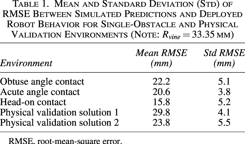
RMSE, root-mean-square error.
Long-horizon design optimization
We assess the effectiveness of our design optimization framework across six different environments, each designed to test specific aspects of the planning approach and environmental interaction capabilities. The evaluation environments, illustrated in Figure 8, span a range of planning challenges:
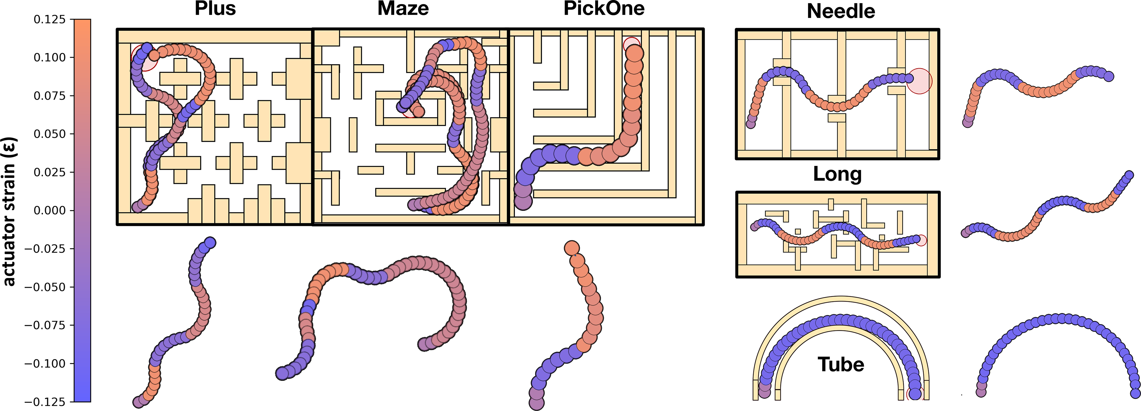
Multiple solutions found for the six evaluation environments by our design optimization approach. Our approach successfully identified solutions for: complex navigation through clutter (Plus, Maze, and Pickone), navigation through tight constraints (Needle), precise contact exploitation (Long), and trivial solutions when they exist (Tube). Free-floating images display the final actuated vine shape in free space.
Our design optimization framework successfully identified feasible solutions for all evaluation environments, as demonstrated in Figure 8. Even in the more difficult environments such as Maze, Long, and Needle, which are cluttered, full of dead ends, and require precise movement, our planner effectively discovered minimum-actuator designs that exploited contact with the environment to achieve the task objective.
We evaluated the planner with and without the reverse tree heuristic over 30 independent runs on each environment; statistics are reported in Table 2. The planner had consistent performance; all environments achieved initial solutions within 60 s on an AMD Ryzen 9 5900 CPU and NVIDIA RTX 3050 GPU, enabling interactive design iteration and deployment with a desktop computer.
Comparison of Planning Performance with (Default) and Without (No Geo) Geometric Heuristic Guidance
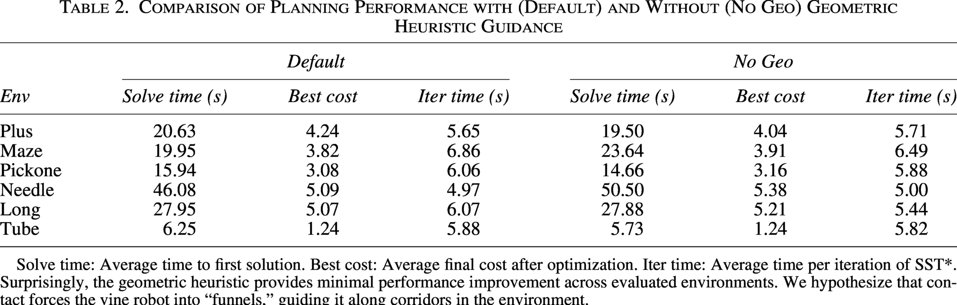
Solve time: Average time to first solution. Best cost: Average final cost after optimization. Iter time: Average time per iteration of SST*. Surprisingly, the geometric heuristic provides minimal performance improvement across evaluated environments. We hypothesize that contact forces the vine robot into “funnels,” guiding it along corridors in the environment.
Robustness of designs
Figure 9 presents the success rate of reaching the goal region as a function of uncertainty in both the environment and actuation parameters, in the same environment as Figure 6. We model environmental uncertainty through Gaussian perturbations of obstacle positions and sizes with gradually increasing variance levels. Similarly, actuation uncertainty is modeled through perturbations of actuator pressure and length parameters. For each level of uncertainty, we evaluate success rates across 1000 trials.
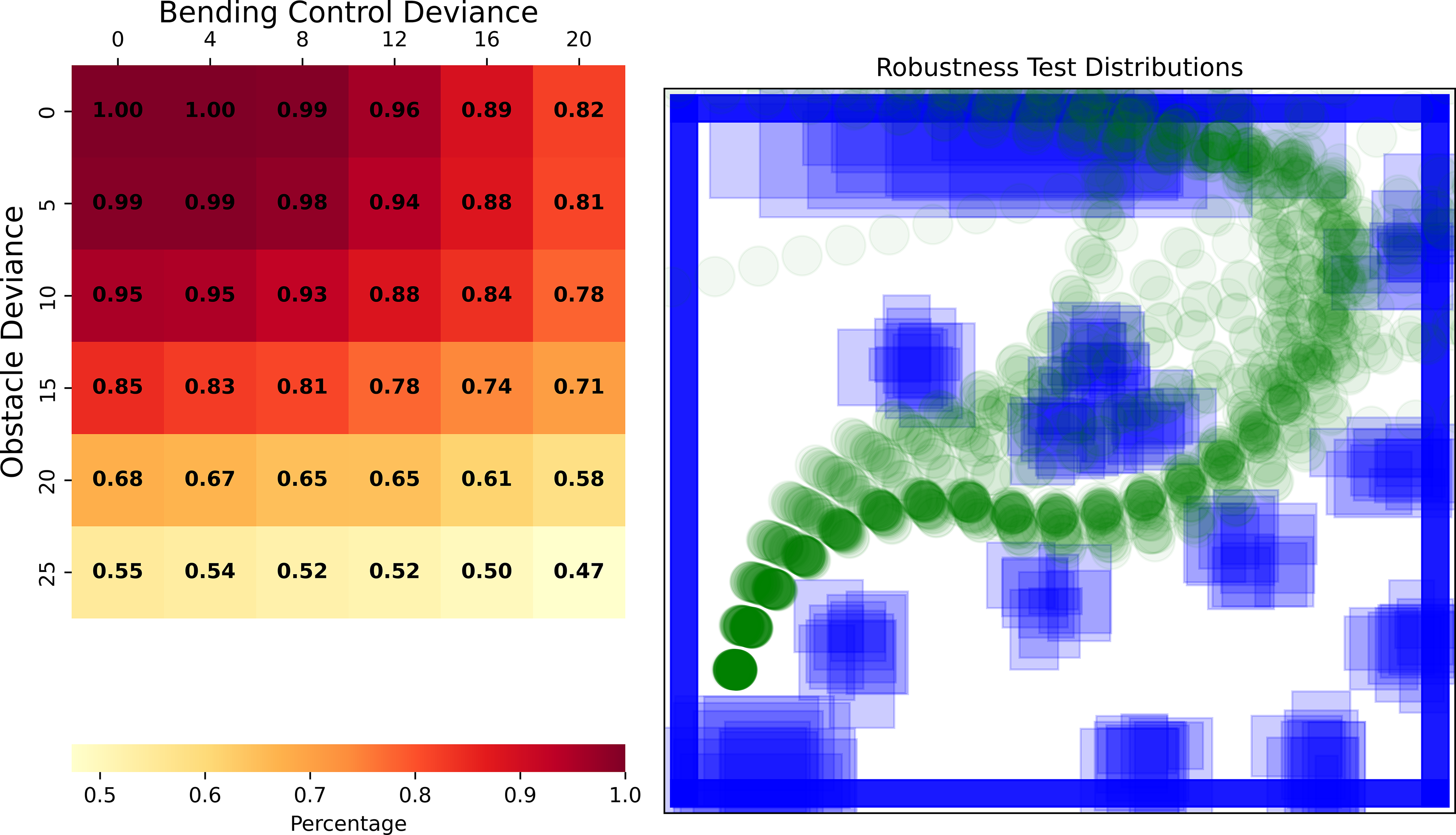
Left: Robustness test of a nominal design over Gaussian noise applied to obstacles and produced design. Scale for obstacle shift is the percent size difference and position change. The scale for bending control shift is the percent change to actuator pressure and actuator length. Each division was run with a sample size of 1000, and the fraction of successes is reported. Right: Examples of 10 sampled environments at the highest obstacle deviation and 60 rollouts with varying bending control deviation from the same nominal design. The “funneling” effects of contacts are clear: even with variations in obstacles and designs, the vine robot is pushed down similar trajectories.
Results show graceful degradation of task satisfaction with increasing uncertainty levels and that designs generated by our framework have inherent tolerance to uncertainties, particularly when contact interactions provide environmental guidance that compensates for actuation variations. This supports the deployment of found designs in real-world environments where the perfect transfer of simulation to reality is unattainable.
Funneling behavior
A separate study was run to investigate the vine robots’ inherent tendency to display funnel-like behaviors after contact with obstacles, which causes trajectories with minor deviations to converge. 13 Figure 10 illustrates 50 vine rollouts with uniformly distributed starting angles in 4 environments as obstacles gradually become denser. Some variance was introduced to the bending controls to bias growth towards the top right corner. Dispersion statistics were run on the endpoints of the trajectories and are displayed in Figure 11.
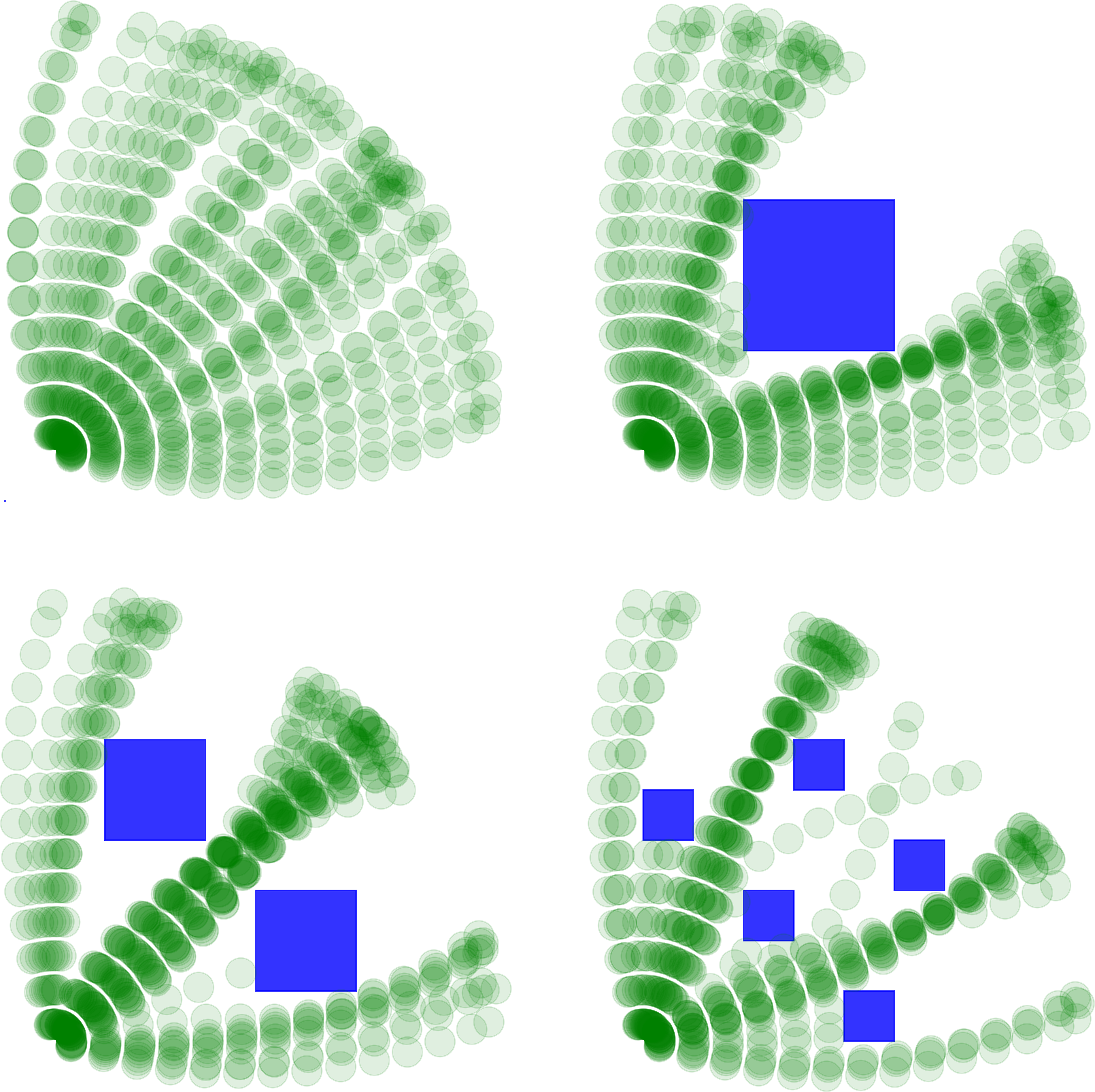
Vine rollouts are run with slight deviations to start angle. The environment with no obstacles shows the even spread of vine trajectories. The other environments show the funneling behavior, forming highways where many trajectories converge.

K-nearest neighbors concentration density ratio across multiple values of k and the four environments shown in Figure 10.
Dispersion analysis was done using the k-nearest neighbor density concentration ratio of the top 10 percent of clusters. Given an endpoint of a vine trajectory 
The larger
Discussion
This work introduces a unified modeling framework for soft growing robots, effectively capturing the interactions between pneumatic actuation, beam mechanics, and environmental contact. The innovative neural surrogate approach allows for efficient simulation of vine robots, achieving a computational speedup of four orders of magnitude compared to traditional methods. This advancement enables faster-than-real-time simulation, which is crucial for developing a contact-aware design optimization framework. In this section, we discuss the performance and limitations of our framework and highlight major advances.
Capturing actuator–contact interactions
The single-obstacle environment experiments in Sec. 6.1 demonstrate that our simulator captures the fundamental contact-actuation coupling accurately across the range of contact conditions. The simulator is able to capture both the constant curvature bends produced by free space actuation or contact in a direction of bending and the discrete buckling when actuation and contact direction are opposed. Due to the nonlinearity of the sPAM bending model and contact mechanics, these configurations exhibit asymmetrical behaviors and yield substantially different final robot configurations. This match is maintained for multiobject interactions, with only a slight increase in RMSE, likely due to the longer length between contact events.
It should be noted that small deviations in the simulator before obstacle contact, such as start position and heading angle, can cause divergence on contact, as contact direction and force often dominate and can “funnel” the robot into different homotopy classes of motion through the environment (e.g., hitting on one side of an obstacle vs. another). This sensitivity is underscored by our funneling behavior evaluation in Sec. 6.4. While many neighboring trajectories seen in Figure 10 clumped up in final tip position, starting angles hitting on either side of an obstacle corner ended up further apart after contact.
Application to long-horizon design optimization task
To assess the performance of the design optimization framework, we selected six different simulated environments. These environments were explicitly designed to capture important aspects of the planner’s ability, such as (1) picking a better solution from multiple alternatives, (2) handling tight geometric constraints, and (3) identifying trivial solutions.
The Long environment validates the core hypothesis of our approach: the planner successfully identified designs that exploit deliberate contact interactions to navigate passages that would be inaccessible without environmental support. This demonstrates the practical advantage of contact-aware design optimization over traditional collision-avoidance approaches. This is also evidenced in the Tube environment, where the planner consistently produced near-optimal solutions with only one or two segments, indicating successful identification of minimal-actuation designs despite the availability of more complex alternatives. For environments with multiple viable solution paths (e.g., Plus and Maze), the planner demonstrated breadth of exploration, identifying diverse design alternatives that utilize different environmental corridors. This capability provides designers with multiple implementation options with different potential robustness against environmental variations.
Surprisingly, the reverse tree heuristic did not provide substantial performance improvements across the evaluated environments, even for more complex scenarios like Pickone and Maze that feature dead-ends and branching passages where heuristic guidance would be expected to provide benefit. We hypothesize that the natural funnel-like behavior exhibited by vine robot dynamics—particularly the tendency for contact interactions to guide the robot toward feasible solutions—reduces the need for explicit guidance in environments of the scale we evaluated. This observation suggests that the inherent physics of vine robots implicitly guides the system, obviating the need for other heuristics.
The real-world multiobstacle environment in Figure 6 shows a concrete example of the practical applications of our fast simulation framework in a contact-aware design optimization task. The planner finds designs of vine robots with minimal numbers of actuators within the constraints of feasible actuator fabrication and control. This example specifically highlights the ability to navigate through inaccessible passages (due to limits in actuator strain) by leveraging environmental contact. The validation of the model and simulator through real robot experiments highlights their robustness, with results indicating that the mean RMSE is of the same order as the vine robot radius. Deviations of this magnitude are within acceptable tolerance for the navigation tasks considered, particularly given the inherent uncertainties in fabrication, deployment, and measurement.
Effects of contact on robustness through funneling
The robustness tests (Sec. 6.3) quantified the effect of uncertainties in the environment, such as obstacle positioning, and vine robot actuation parameters. The results from the robustness tests indicate that the vine robot’s behavior in an obstacle-rich environment is highly robust to these uncertainties. Only with greater than 10% variation in obstacle or 12% variation in bending control does the success rate drop below 90%. Eventually, greater deviance in either environment or design will cause more significant failures, as the deviance in rollout becomes more likely to change the initial wall contacted, leading to a different homotopy of the final path. The funneling behavior tests (Sec. 6.4) showed that the vine robots indeed display funnel-like behavior that creates concentrated trajectories after contact with obstacles. These results together show that minor deviations in vine bending control have little effect on overall vine trajectory due to effects from contact forces, though this behavior shifts dramatically after a certain point.
These evaluations also reinforce our earlier observation that contact-guided navigation provides natural error correction that maintains overall success despite small deviations in behavior. An interesting direction for future work would be to explicitly target designs that exploit behaviors that are inherently more robust to uncertainty due to this effect.
Generalizing to different actuator and control models
While we used sPAMs as active steering actuators, other actuation methods,18,30 such as the serial pouch motor, the cylindrical pneumatic artificial muscle (cPAM), the fabric PAM, and tip steering, can be used in our simulator due to the modular feature of our framework. The neural surrogate approach used for sPAM model integration can be easily replaced with similar neural surrogate or first principle models for cPAMs and pouch motors.
The current framework is also implemented as an open-loop control task, where the vine robot design (vine robot length, actuator placement, and actuation pressures) is selected during fabrication and remains fixed throughout the deployment. However, this can be easily extended to enable time-dependent or position-dependent steering change. Through initial simulation examples in the Supplementary Data, we showed how tip steering could be added to the modeling framework by temporarily penalizing growth and changing steering command.
Limitations
Despite these promising results, the current simulator and planner have limitations. It is confined to planar environments and relies on several assumptions about pressure dynamics, which become less realistic with longer robot growth. The current framework does not take into account the mass and inertia of the vine robot, thus limiting its use for vine robots without a tip mass or tip-based retraction mechanism. 53 For the planner, due to its planning-as-design approach, it is currently unable to generate solution that generalize to multiple environments. While this is not an inherent limit, more work would likely be needed to expand the actuator design space to perform multiobjective design optimization. Additionally, the design framework was tested in relatively simple scenarios due to constraints on the total length of the robot in the physical experiment in order to maintain a consistent tail tension and therefore growth pressure, limiting its ability to demonstrate long-horizon guidance through geometric heuristics. Longer lengths of vine robots tend to have internal friction, not currently addressed by the constant growth pressure assumption. 22 In practice, pressurized base stations offer better control over vine robot pressure over long lengths, so future work will look to integrate the planner designs with the closed-loop control of growth rate enabled by a pressurized base station. A future model would need to consider the effect of tail tension to simulate controlled growth and retraction.
Conclusion
The unified modeling framework and fast simulation approach introduced in this work significantly advance the field of soft growing robots, allowing for fast, efficient, and accurate simulations. The contact-aware design optimization framework provides a novel method for creating robust vine robot designs to navigate a known environment. More research is needed to address the current limitations, such as the model’s restriction to planar environments and the simplicity of the tested scenarios. Additionally, exploring cost functions that utilize the characterized funneling effects of contact forces could enhance robustness and reduce uncertainty. Another interesting area for research could be the integration of sensing modules in the simulation framework to enable real-time feedback-based closed-loop control of vine robots.
Our work opens new avenues for exploration in addressing the challenges of soft robot path planning and control. A natural extension of this framework is to tackle multiobjective optimization tasks involving high-level reasoning and long-horizon navigation, such as payload deployment, manipulation of objects, and navigation in unknown environments. Ultimately, the advances in simulation frameworks will be the basis on which intelligent, autonomous vine robots are built.
Authors’ Contributions
Y.G. and L.C. developed and evaluated the simulation and planning framework and assisted in physical validation. P.B. and S.W. developed the combined actuation and contact moment model and physically validated the approach. Z.K. and L.H.B. supervised the project. All authors discussed the results and contributed to the final article.
Footnotes
Acknowledgment
The authors thank Gilbert Chang for feedback on this article.
Author Disclosure Statement
The authors have no conflicts of interest to declare.
Funding Information
This work was supported in part by NSF FRR 2308653. This material is based upon work supported by the United States Air Force (AFMC AFRL/RXNW) under Air Force Contract No. FA2394-24-C-B060.
Supplemental Material
Supplemental Material
Supplemental Material
Supplemental Material
References
Supplementary Material
Please find the following supplemental material available below.
For Open Access articles published under a Creative Commons License, all supplemental material carries the same license as the article it is associated with.
For non-Open Access articles published, all supplemental material carries a non-exclusive license, and permission requests for re-use of supplemental material or any part of supplemental material shall be sent directly to the copyright owner as specified in the copyright notice associated with the article.
