
Abstract
Aiming at the finishing machining difficulties of metal parts with internal cavity walls and apertures in the equipment manufacturing industry, the study proposes a polishing method with In21Sn12Bi49Pb18 low-melting-point alloy abrasive. First, the oil-granting nozzle made of 304 stainless steel powder bed fusion technology is taken as the research object, and four key parameters, namely, pressure of inlet, kinematic viscosity, strength of magnetic, and system temperature, are introduced by combining numerical simulation of computational fluid dynamics and orthogonal experiment. The results of the study show that the optimal combination of processing parameters is the kinematic viscosity of 1.5 Pa·s, magnetic field strength of 40 A/m, inlet pressure of 4 MPa, and system temperature of 80°C. Under the optimal processing parameters, the surface roughness in the region for the oil-granting nozzle’s small hole region was reduced to the level of 0.13 μm.
Introduction
In the equipment manufacturing industry, finishing machining of metal parts with complex profile and high surface quality requirements for internal cavity walls and apertures is still a technical challenge.1–3 Abrasive flow precision polishing is the process of deburring, removing flying edges, and rounding corners by flowing an abrasive media under pressure over the surface of the workpiece to be machined. It reduces the corrugation and roughness of the surface to achieve the finish of precision machining.2,4 Selective laser melting (SLM) is currently the hottest technology in metal additive manufacturing. It is used to control the sintering movement of the fiber laser on the powder bed by means of a galvanometer, and the layers are stacked and shaped. The shaping accuracy of SLM technology can reach 0.1 mm, which is suitable for making metal parts with various complex inner runner structures. However, the forming process will produce a lot of metal splash, and the splash cannot be blown away in time to affect the quality of the next layer of forming. Due to the difference in the forming surface of each layer, there is a significant quality uncertainty. SLM technology is used in a variety of applications, one significant use being the manufacture of oil-granting nozzle components for refueling equipment such as petrol pumps at petrol stations. The defects of SLM technology may have a negative impact on the fuel flow and refueling process, such as decreasing the efficiency of the refueling process, increasing the risk of spattering, and even leading to leaks. 5 If the precision of the workpiece is required to be very high, it needs to be achieved later by postprocessing such as finishing. The surface defects of the oil-grain nozzle made by SLM are shown in Figure 1.
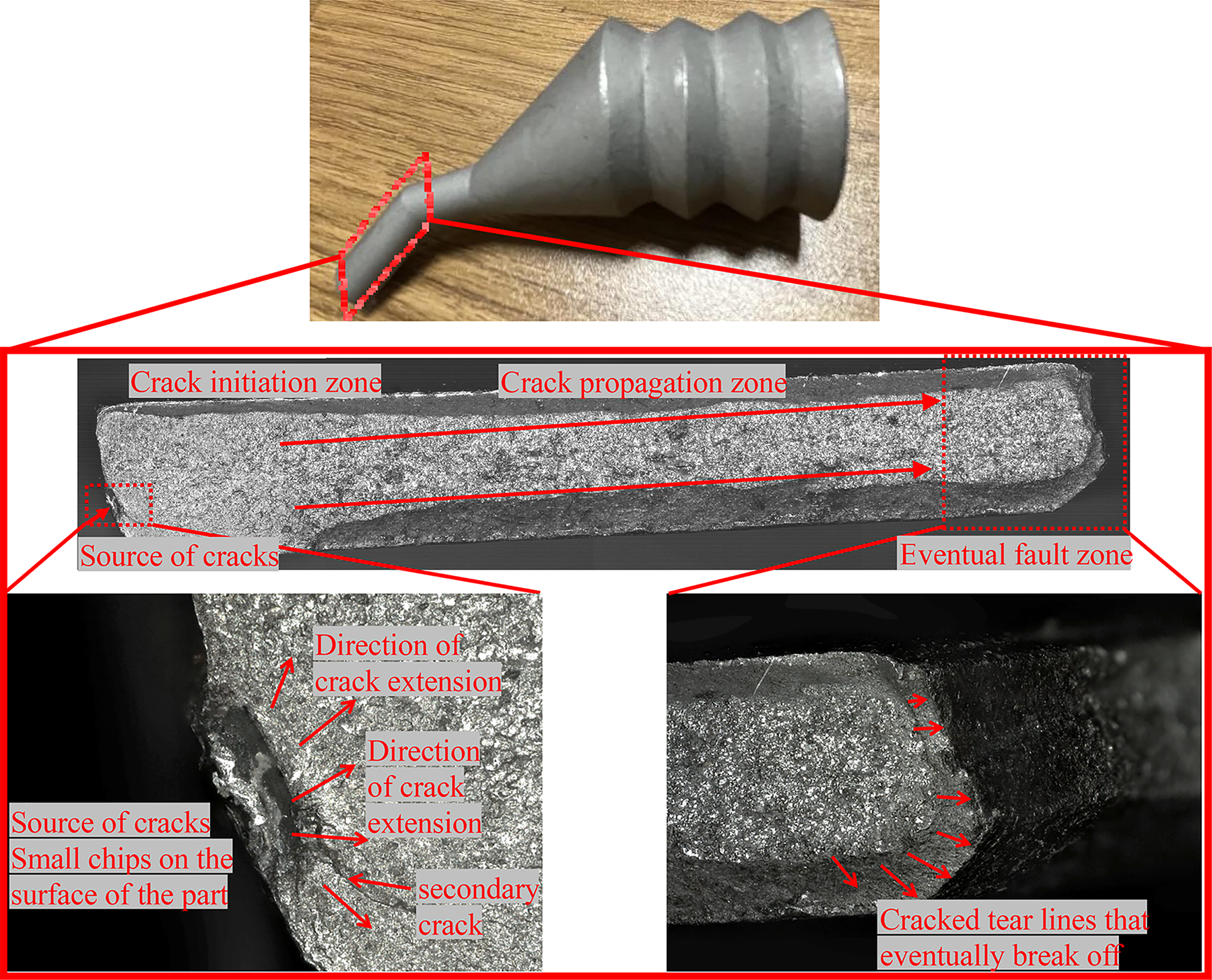
The surface defects for selective laser melting of the oil granting nozzle.
As shown in Figure 1, the donor nozzles made by SLM technology have surface problems in their small hole region. This is due to the fact that the SLM technique is influenced by factors such as temperature and cooling rate. If the temperature gradient or cooling rate is not appropriate, nonuniformity of the material can be triggered, leading to the formation of highly stressed areas at the exit, which may trigger surface defects. Surface defects may have a negative impact on the performance and reliability of the applicator nozzle, leading to oil leakage, reducing the life of the applicator nozzle and even affecting the uniformity and direction of the jet stream. The heat distribution during the SLM manufacturing process is more difficult to control; therefore, the possibility of unmelted powder within the manufactured part exists. 6 In addition, laser energy fluctuations, inconsistencies in powder size, and so on can also create defects in the internal flow path of the impart nozzle by affecting changes in heat distribution.
With the development and application of polishing technology, many scholars at home and abroad have gained a deeper understanding of the process and mechanism of polishing processing. Such as the contact morphology of the abrasive and the material surface in the polishing process, the friction and wear mechanism, and the action mechanism of the liquid polishing agent have become the hot spots of research.7–10 At the same time, more and more studies have begun to explore the use of computer simulation and data analysis and other methods. Thereby, the polishing process is simulated and optimized to achieve a more accurate polishing process.11–14 Li et al. 15 focused on the evolution of surface morphology and transient melt pool dynamics in the overmelt mechanism of laser polished surfaces. A model based on a moving heat source was developed to show the distinctive bulges and depressions of the polished surface. The results of the study show that the surface roughness undergoes a significant decay during the polishing process. However, the scope of the study is more limited and has not been experimentally validated as well as predicted over a wider range of parameters. Li et al. 16 aimed to improve the machinability of metallic materials and proposed a method based on laser integral grinding process. The results of the study showed that the metal material exists at a higher temperature in the region close to the heat source, which has a significant effect on the structure and properties of the metal material and provides a basis for the optimization of the grinding process. Li et al. 17 carried out numerical simulation and experimental study on S-bend pipe with side openings. The results of the study showed that the dynamics of the abrasive flow varied significantly under different inlet conditions. However, the study did not use optimization algorithms to predict the best design configurations to meet specific hydrodynamic demands or to reduce energy losses. Wang et al. 18 proposed a three-dimensional multiscale numerical simulation method in improving chemical mechanical polishing (CMP) for solving the problems of boundary effect-induced boundary layer thickness detection and processing efficiency degradation of wafers. The study provides a theoretical basis for the compensation of boundary signals in the CMP process. Guo et al. 19 explored the effects of collision angle and grinding rate on the polishing effect of shear thickening polishing and proposed a model for the removal rate of materials by shear thickening slurry. The results show that the method can significantly improve the surface finish in a short time.
Zhao et al. 20 addressed the field of electrohydrodynamic fluid-assisted polishing in terms of the feasibility and performance of this technology in the processing on electronic and optical devices. The results of the study show that controlled machining of metal surfaces can be achieved by using miniature needle electrodes. This research provides a new way for high-precision machining. Meng et al. 21 aimed to improve the quality and productivity for rice comminution by proposing a mathematical model based on the prediction of rice abrasion. The study provides a useful tool in agriculture by obtaining the relationship between rotational speed and wear through polynomial fitting method. Jiannan et al. 22 proposed a surface adaptive polishing technique to enhance the surface accuracy of optical free-form surfaces. A multiscale theoretical model is also constructed to accurately predict the generation of surface microforms. The results show that the multiscale theoretical model can accurately predict the surface microforms, which provides important support for optical precision manufacturing. Hashmi et al. 23 reviewed the application of mathematical modeling and simulation techniques in different abrasive machining methods; furthermore, this review literature will be of great value to researchers studying the mathematical modeling of various micron and nanofabrication techniques in different applications. Meng et al. 24 aimed to address the high-precision requirements faced by silicon carbide materials, and the study proposed an innovative ultra-high-precision machining method. The simulation results show that the application of the method can significantly improve the surface morphology, polishing force, and friction coefficient with the increase of groove depth. The study provides an important contribution to meeting the high-precision requirements of silicon carbide materials. Heshmat et al. 25 evaluated the ability of slurry impact to improve the surface roughness of parts manufactured using FDM. Three main factors were introduced: construction direction, layer thickness, and the impact angle of the slurry particles. In the experiment, a test rig was used to evaluate the effect of these factors on surface roughness. Statistically, analysis of variance (ANOVA) and regression analysis were carried out to investigate the effect of each factor on roughness. However, the study is prone to overpolishing of the workpiece, and its polishing stability needs to be further improved. Heshmat et al. 26 explored the effect of hot air jetting on surface roughness improvement by introducing it in the FDM printing process. The research experiments focused on two key factors, airflow temperature and nozzle translation speed, with ANOVA and regression analyses to quantify the effects of these factors on the process response. The results show that the hot air jet can locally melt and smooth the surface steps, resulting in a significant improvement of about 65.3% in the average roughness, demonstrating the important role of these two factors in optimizing the surface quality of FDM printing. However, their selection factors are fewer, and the average roughness enhancement effect is limited.
In this study, we focus on addressing the challenges associated with the finishing machining of metal components featuring internal cavities and apertures in the equipment manufacturing industry. To tackle this issue, we introduce a novel polishing method utilizing In21Sn12Bi49Pb18 low melting point (LMP) alloy abrasives. The primary objective is to enhance the surface quality of metal components, specifically the oil-granting nozzle fabricated through 304 stainless steel SLM technology. In this work, the aim is to introduce and derive the optimal combination of processing critical parameters by combining the computational fluid dynamics (CFD) numerical simulation with orthogonal experiments.
Materials and Methods
The preparation of LMP alloy abrasive
Silicon carbide, cubic boron carbide, diamond powder, and other hard raw materials were used as polishing grits in terms of traditional abrasives, to which avoiding overpolishing is a great technical challenge. This study proposes a system for the finishing process of the oil-granting nozzle made of SLM technology, which is made of 304 stainless steel. Stainless steel 304 is a relatively hard material, and applying soft alloy abrasives with LMP may reduce the potential damage possibility to the surface of the workpiece during the polishing process.27,28 In summary, the study proposes a low melting alloy (LMA) abrasive consisting of tin (Sn), lead (Pb), bismuth (Bi), cadmium (Cd), indium (In), and other elements.29–31 The reason for choosing a LMA is first that its melting point is much lower than that of conventional metal materials, which makes it able to melt and flow at a lower temperature, thus contacting the workpiece surface to achieve precise control of the polishing process. Second, LMAs usually have good fluidity after melting, which helps them to cover the surface of the workpiece evenly and improve the polishing effect. At the same time, the good fluidity also facilitates the adjustment and control of the alloy during processing. Finally, the use of LMAs as polishing abrasives can reduce potential damage to the workpiece surface. Because the alloy can melt and flow at a lower temperature, the thermal effect of high temperature on the workpiece surface can be avoided, thereby reducing adverse factors such as thermal stress and thermal deformation. LMA abrasives have simple component and do not require auxiliary abrasive polymers. They have a LMP, with a melting temperature of 50–80°C. They can efficiently polish and deburr, without producing structural and organizational changes to the polished parts, and they do not overpolish.32,33 In this study, four LMP alloys with appropriate temperature ranges are selected, namely In-Sn-Bi, In-Sn-Bi-Pb, Sn-Bi-Cd-Pb, In-Sn-Bi-Cd-Pb, and In-Sn-Bi-Cd-Pb. The melting points and densities of these four alloys at different composition ratios are compared, and the morphology states at different temperatures are shown in Figure 2.
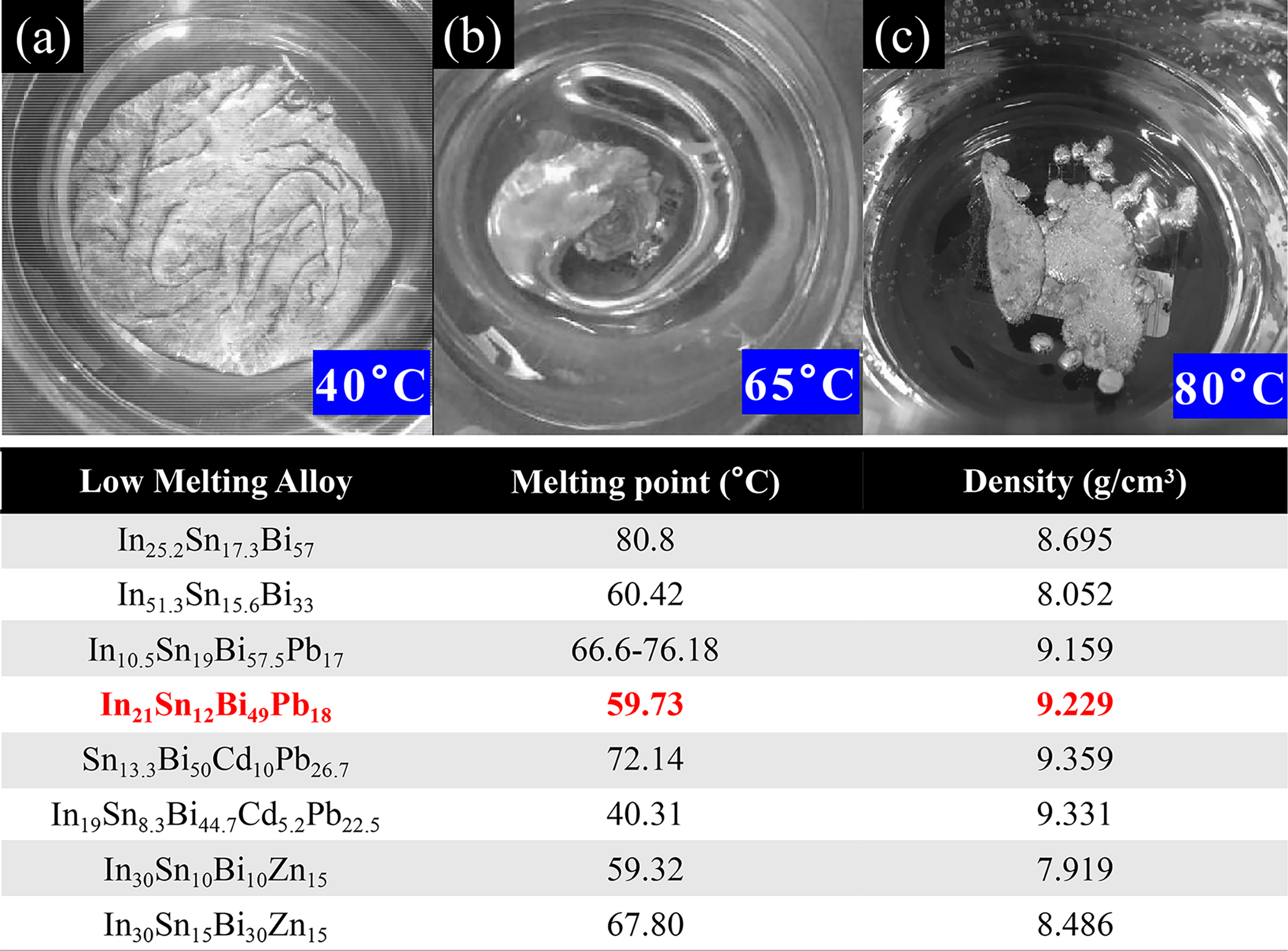
The morphology of In21Sn12Bi49Pb18 alloy at different temperatures
As shown in Figure 2, it is obvious that the In21Sn12Bi49Pb18 alloy has a LMP, specifically 59.73°C. This allows it to flow and contact the surface of the workpiece at a relatively low temperature during the polishing process. It helps precisely control the polishing process. In addition, the density of the alloy is 9.229 g/cm3, which indicates that the alloy abrasive has a high density. It can be used to effectively remove irregularities from the surface of the workpiece and also to avoid overpolishing the workpiece. The composition of the alloy is compatible with 304 stainless steel, helping to reduce the risk of reacting with 304 stainless steel or introducing external impurities during the polishing process. Figure 2a represents the morphology of the alloy abrasive at 40°C, from which it can be clearly seen that the alloy surface is in a solid powder state when the temperature has not reached the melting point, so the system working temperature can be precisely controlled to adjust the degree of polishing of the workpiece. Figure 2b represents the morphology of the alloy abrasive at 65°C. It can be clearly seen that the abrasive becomes molten at this temperature, which indicates that the alloy may start to melt and form a liquid state when the alloy is close to or exceeds the melting point temperature of the alloy. Figure 2c represents the morphology of the alloy at 80°C, from which it can be clearly seen that the alloy is completely in the liquid state. The above morphology situations of the alloy at different temperatures indicate that the alloy will melt and become liquid when it approaches and exceeds its melting point temperature. From the above, it can be seen that in order to achieve the desired polishing results, choosing the right processing temperature is necessary for precise polishing control, ensuring that the alloy starts to flow and comes into contact with the surface of the workpiece only when it is needed.
In summary, the abrasive composition of LMA is single, and no auxiliary abrasive polymer is required. The melting point is low, and the melting point temperature is between 50°C and 80°C. At the same time of efficient polishing and deburring, there will be no structural and organizational changes to the polished parts, and there will be no overthrowing phenomenon.
The principle of processing system
To polish the oil-granting nozzles made of 304 stainless steel with LMP alloy abrasives, a specialized LMP alloy abrasive polishing deburring system for media flow channel was designed. Its aim is to provide a suitable media carrier for this alloy abrasive for the best polishing results. The structure of the system is shown in Figure 2. The system consists of a fluid preparation system, a polishing deburring system, a cleaning system, and a hot air drying system. A cleaning device is connected to the upper end of the cleaning fluid preparation platform, and a hot air drying device and a control device are connected to the middle of the upper end of the rack. A polishing platform is connected to the right side of the upper end in the frame, and an assembly is connected to the upper end of the polishing platform. The polishing device, cleaning device, hot air drying device, and assembly body are connected to each other. The abrasive is mainly LMP alloy abrasive, and the metal parts with complex shape surface and high surface quality requirements of inner cavity wall and aperture are subjected to finishing processing. The system is shown in Figure 3.
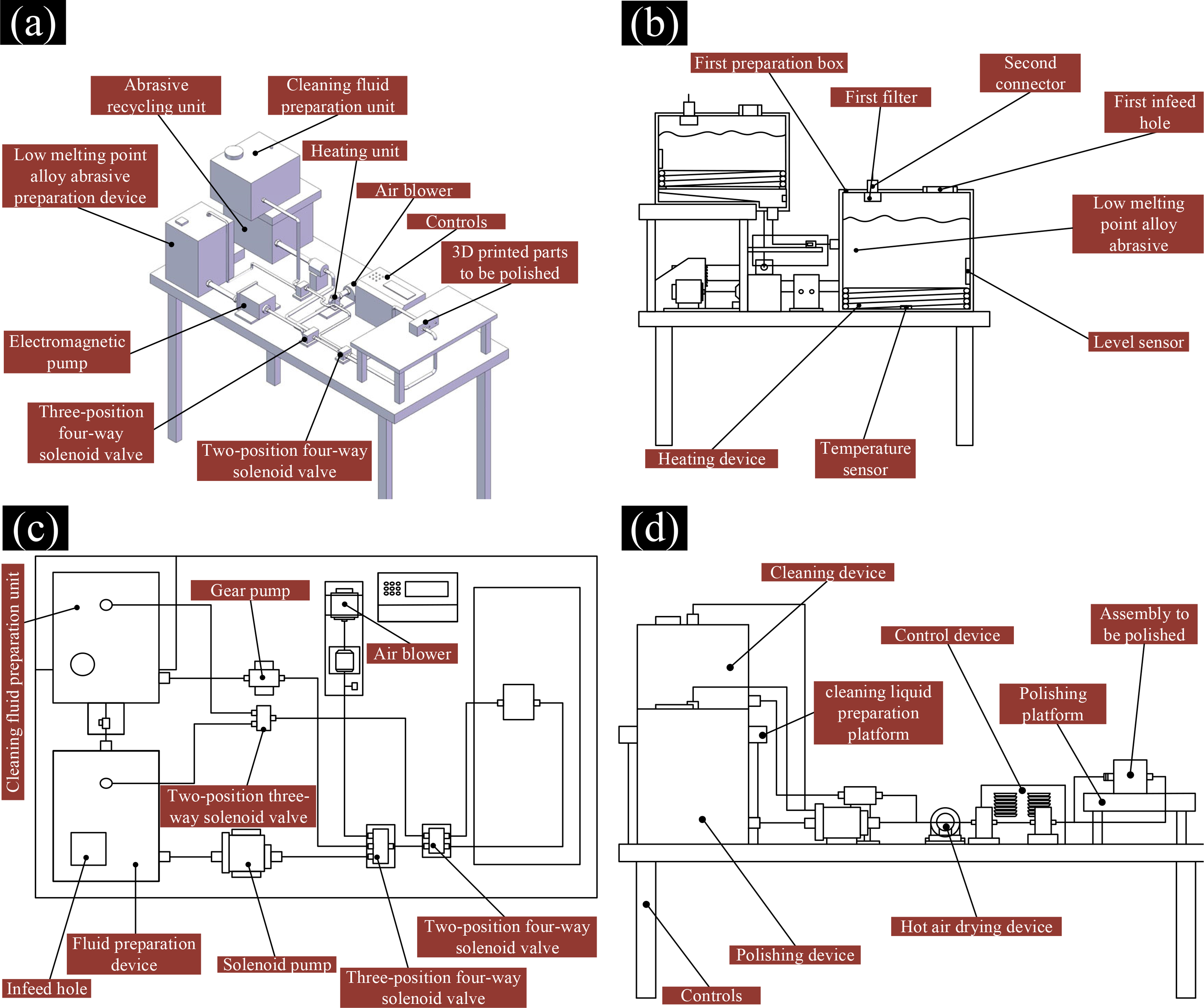
Schematics of
As shown in Figure 3, the media flow channel abrasive flow polishing system mainly includes a LMP alloy abrasive preparation system, a polishing deburring system, a hot air drying system, and a cleaning solution preparation system. Figure 3b represents the principle of LMP alloy abrasive preparation. The process ensures that the LMP alloy is heated to a molten state in the first preparation chamber and monitored by temperature and liquid level sensors to ensure that the temperature and liquid level are in the appropriate range. The system can thus obtain the required LMP alloy fluid in preparation for subsequent polishing and deburring. Figure 3c represents the principle of the polishing deburring and hot air drying system, which works by using the control device to activate the electromagnetic pump. A three-position four-way solenoid valve, a two-position four-way solenoid valve, and a two-position three-way solenoid valve are used to control the flow direction of the LMP alloy. Subsequently, the LMP alloy abrasive will return to the first preparation box. The whole process will continue to complete the workpiece polishing deburring process. Figure 3d represents the working principle of the cleaning system. Pure water is chosen as the cleaning fluid because the LMP alloys’ melting point is between 65°C and 75°C, and the boiling point of pure water is higher than this value, so it can be used as the cleaning fluid for this system. The cleaning solution is injected into the preparation tank through the feed hole. The heater is then activated by a control device to heat the cleaning fluid to a set temperature value of about 80°C, which is higher than the LMP alloys’ melting point. The heating temperature of the cleaning fluid is also monitored using a temperature sensor, and the liquid level of the cleaning fluid is monitored using a liquid level sensor.
The model of polishing with LMP alloy
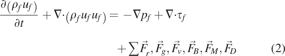
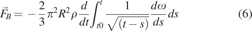
During the whole system processing, repeated collision and friction between the LMP alloy abrasive and the processed material occurs, producing a microscopic grinding effect, which results in the flattening of the processed material’s surface and the improvement of its finish. 34 The abrasive is subjected to a variety of forces in polishing, including gravity, virtual mass force, Basset force, trailing force, buoyancy force, Magnus force, and pressure gradient force. 35 The forces affecting the process are shown in Figure 4.
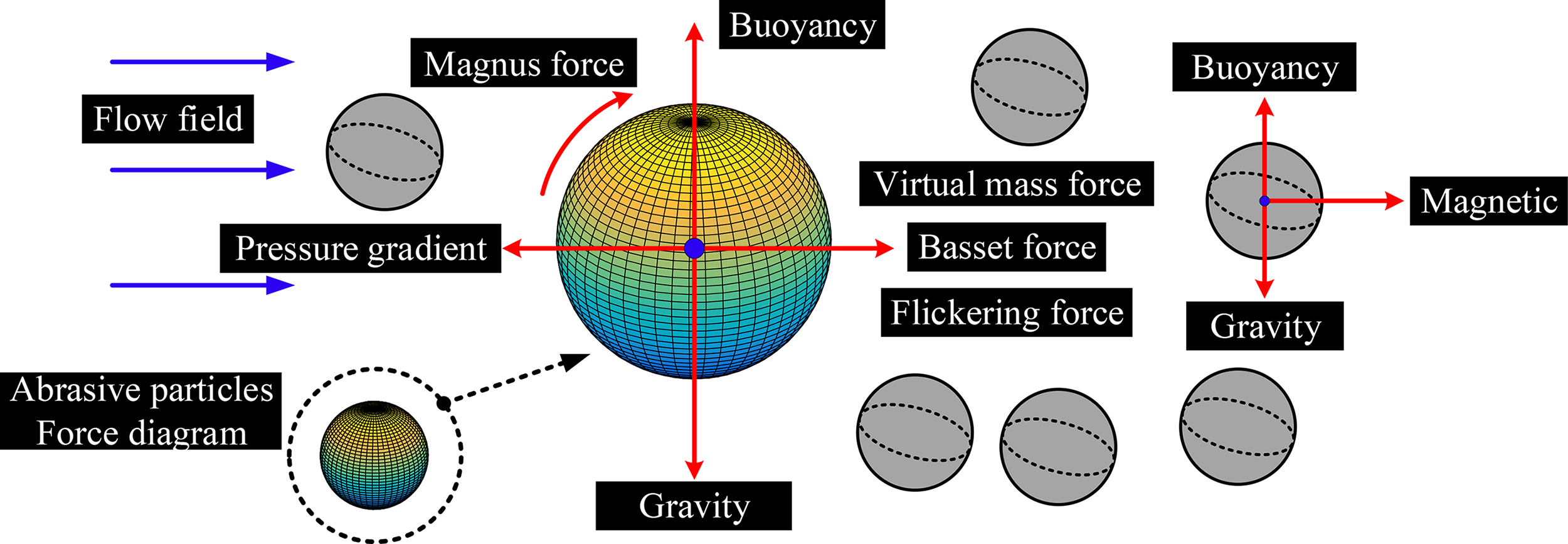
Abrasive polishing process and force analysis.
In the process of fluid polishing workpieces, the velocity and pressure fields of the fluid phase can be obtained by solving the continuous phase control equations to further solve the various forces on the abrasive.
36
In summary, the mass conservation equation and momentum conservation equation are shown in equations (1) and (2).


The model geometry and the boundary conditions
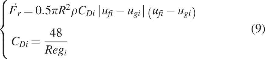
The corrugated region of the actual runner of the nozzle is 20 mm in diameter, the diameter of the small hole region is 2 mm, and the total length is 55 mm. To provide reliable basis and data support for research. This study aims to provide a reliable basis and data support for the research. The mesh partitioning parameters are shown in Table 1.
The Summary of Orthogonal Experimental Parameter Design
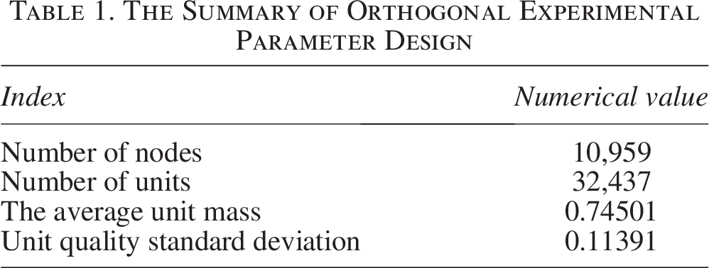
Table 1 shows the division results of the feed nozzle grid flow channels, including the values of related indicators. The number of nodes is 10,959, and the number of units is 32,437. The average cell mass is 0.74501, and the standard deviation of cell mass is 0.11391. The region division and the mesh division of the nozzle are shown in Figure 5.
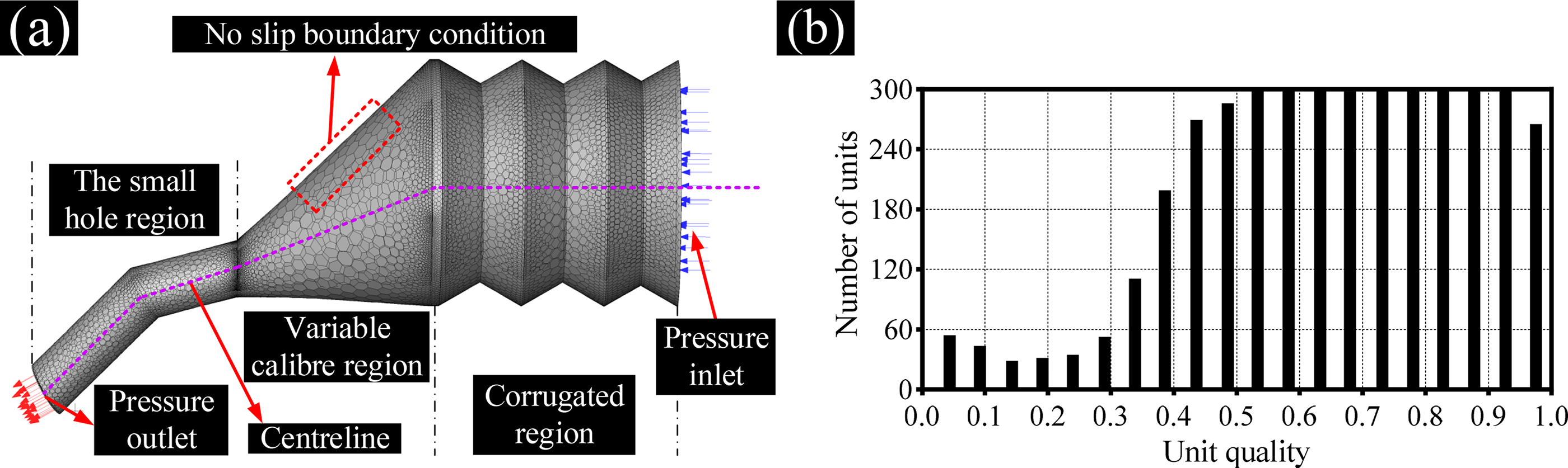
The oil-granting nozzle mesh delineation and quality check.
Figure 5a represents the results of the network delineation of the solid basin of the oil-granting nozzle. The small hole region of the oil-granting nozzle is densely meshed in order to better capture the interaction between the fluid and the geometry. The number of delineated nodes is 10,959, and the number of cells is 32,437. The average cell mass is 0.74501, and the standard deviation of cell mass is 0.11391, which is a good result. Figure 5b represents the results of network quality detection in the oil-granting nozzle. It can be seen that the unit quality index ranges from 0.04361 to 0.97535, and the number of units gradually increases until it reaches the peak. In conclusion, the network quality delineation of the oil-granting nozzle watershed is effective. In this study, the mixture model is chosen as the solution equation for simulating the behavior of solid–liquid two-phase flow.40,41 Calculations are carried out through the Reynolds number equation, which yields that the Reynolds number of the liquid-phase fluid is <2300, which indicates that the liquid-phase fluid does not enter a turbulent state, specifically as shown in equation (10).

The design of orthogonal experiment
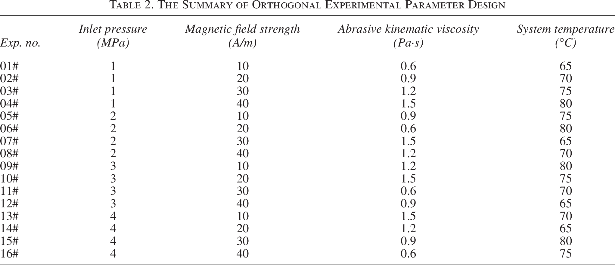
The surface roughness change amount during the actual abrasive flow processing is affected by a combination of factors. Based on the research methodology in the previous section, in order to simplify the experimental steps and to achieve a comprehensive evaluation, the following parts are selected as the system processing parameters for orthogonal tests, which includes the inlet pressure, the magnetic field strength, the kinematic viscosity of the abrasive flow polishing fluid, and the system temperature. The design of the orthogonal tests is shown in Table 2.
The Summary of Orthogonal Experimental Parameter Design
Analysis of Numerical Simulations
The influence of magnetic field strength on the process
The study analyzes the fluid numerical simulation of the oil-graining nozzle to obtain the effect of precise cutting process of LMP alloy abrasive on the small hole region. Through numerical simulation, the effect of four system machining parameters on the machining effect of the oil granting nozzle is analyzed, namely pressure of inlet, kinematic viscosity, strength of magnetic, and system temperature. This is for obtaining a quantitative understanding of the machining technique on the performance of the oil-granting nozzle. The system controls the magnetic field strength by adjusting the system voltage. As the voltage increases, the magnetic field strength increases. The simulation is set with initial conditions of inlet pressure of 1,000,000 Pa and an abrasive kinematic viscosity of 0.8 Pa·s. The numerical simulation results are specifically shown in Figure 6.
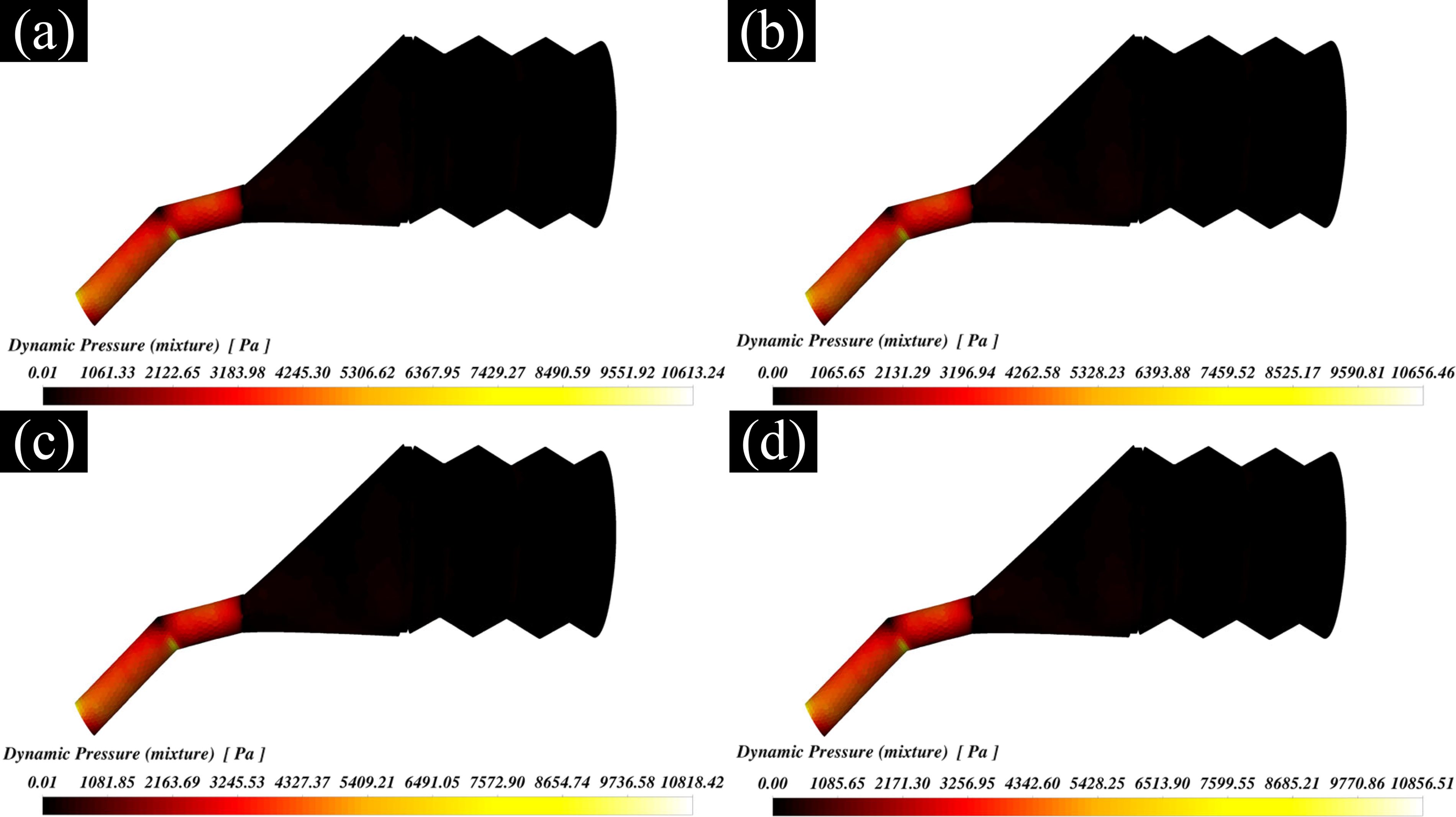
Clouds of dynamic pressure at different magnetic field strengths for the oil-granting nozzles.
Figure 6 represents the dynamic pressure cloud of the oil-granting nozzle under different magnetic field strengths. Under different magnetic field strengths, the dynamic pressure in the corrugated region is lower than that in the small hole region, whereas the dynamic pressure change in the corrugated region is relatively flat. The dynamic pressure is maximum near the small hole region of the oil granting nozzle. The dynamic pressure has a strong relationship with the flow rate. The LMP alloy is discharged from the corrugated region before it is discharged from the nozzle’s small hole region, and the total amount of abrasive flowing through the nozzle per unit of time is equal due to the change in the aperture diameter. The increase in flow rate in the small orifice region of the oil-granting nozzle results in an increase in the dynamic pressure in the small hole region. The change in dynamic pressure reflects the intensity of the abrasive movement; as the pressure increases, the flow of abrasive is more intense and the cutting effect on the inner wall surface is more significant. The LMP alloy is used as the power-driven abrasive to ensure effective execution when grinding the workpiece surface at high speeds. Therefore, the proper selection of the inlet pressure is essential in optimizing the effectiveness of the abrasive flow processing. The study provides data on the dynamic pressure in each region for different magnetic field strengths, which can be seen in Table 3.
Dynamic Pressure Table for Each Region of the Nozzle at Different Magnetic Field Strengths

The study can draw the following conclusions by analyzing the data in Table 3: First, under the same magnetic field conditions, the values of the dynamic pressure strength at the three regions are, according to order, corrugated pipe region, variable aperture region, small aperture region, and the value of the dynamic pressure strength increases with the decrease of the aperture diameter. The larger the dynamic pressure, the more intense the flow and the more times it hits the wall. Thus, it makes the processing effect of the abrasive flow better. When the voltage condition is 40 V, the small hole region shows the maximum value of dynamic pressure intensity under the generated magnetic field strength, which indicates that the best machining effect is obtained at the nozzle of the oil-granting nozzle processed by the abrasive flow.
Inlet pressure’s impact on the process
The study is conducted with different inlet pressures as variables, which are set to 1, 2, 3, and 4 MPa, respectively, and the initial conditions include a magnetic field strength of 40 A/m and an 0.7 Pa·s abrasive kinematic viscosity. The study is conducted through numerical simulation analyses of the internal flow paths of the nozzle, and the cloud diagrams of the velocity variations under different inlet pressures are obtained, which are shown in Figure 7.
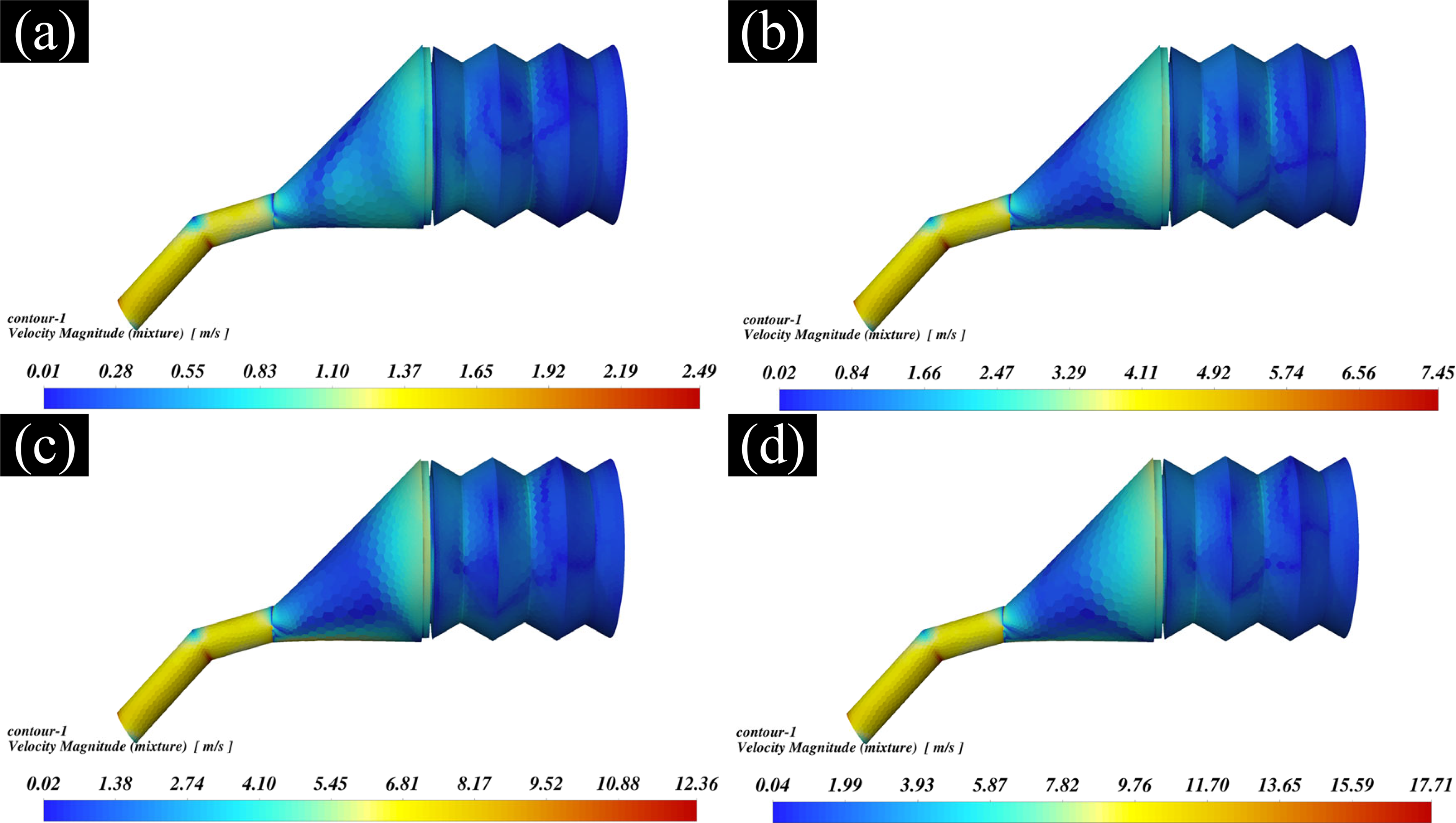
Clouds of velocity magnitude at different inlet pressures for the oil-granting nozzles.
Figure 7 represents the similarity of the fluid movement characteristics of this authorized nozzle under different inlet pressure conditions. No matter how the inlet pressure varies, the abrasive flow rate in the other regions is significantly smaller than the flow rate in the small hole region. In the corrugated region, the distribution law of the flow field is relatively weak, which may be due to the fact that in the corrugated region, the large inner diameter of the oil-granting nozzle, according to the principle of energy conservation, results in the small conversion energy between the abrasives. So, the overall flow rate is relatively smooth. However, during the abrasive polishing process, the abrasive will be squeezed due to the reduction of the pore size, thus enhancing the cutting effect of the abrasive on the inner wall of the oil-granting nozzle. The change in abrasive rate reflects the change in shear force between the fluid and the wall. The higher the velocity, the higher the shear force of the abrasive on the wall, thus achieving better surface polishing. The velocity data for each region at different inlet pressure conditions are presented in Table 4.
Velocity Table for Each Region of the Nozzle at Different Inlet Pressures
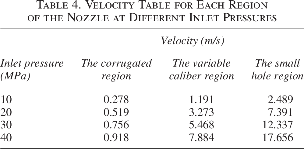
As shown in Table 4, under the conditions of different inlet pressures, the change of velocity in the bellows region is not obvious, whereas the change of velocity in the variable diameter region and the small hole region is significant and has an increasing trend. Especially, the velocity in the small hole region reaches the maximum value at an inlet pressure of 4 MPa, specifically 17.656 m/s. Therefore, based on the results of the numerical analysis, the trend of the velocity change in different regions and the maximum velocity in the small hole region at a specific inlet pressure can be derived.
The influence of kinematic viscosity on the process
Kinematic viscosity is one of the important parameters, which affects the processing of the oil-granting nozzle, and its value depends on the composition and proportion for the components of the polishing fluid. The kinematic viscosity of LMP alloy abrasive is used as a variable, which is set to 0.6, 0.9, 1.2, and 1.5 Pa·s, whereas other initial conditions are fixed at a magnetic field strength of 40 A/m and an inlet pressure of 4 MPa. Through numerical simulation and analysis of the internal flow channel of the nozzle, the wall shear force maps are obtained under different kinematic viscosities, which are shown in Figure 8.
Clouds of wall shear stress at different kinematic viscosity for the oil-granting nozzles.
Figure 8 shows that the shear force in the corrugated region is much less than that in the small bore region under different kinematic viscosity conditions for this nozzle. As the kinematic viscosity increases, there is a decreasing trend in the wall shear in the corrugated region, the variable caliber region, and the small hole region. This indicates that the increase in kinematic viscosity decreases the wall shear force, which reduces the polishing effect of the system on the oil-granting nozzle, which in turns provides some control over the oil-granting nozzle internal wall grinding. In this study, various wall shear stress data will be presented in Table 5 under different flow viscosity conditions.
Wall Shear Stress Table for Each Region of the Nozzle at Different Kinematic Viscosity
As shown in Table 5, under the same region, the wall shear tends to decrease in the bellows region, the variable bore region, and the small bore region with the increase of kinematic viscosity. This shows that the increase in kinematic viscosity may reduce the wall shear force, which has an effect on the machining results and has some control over the grinding process. At 0.6 Pa·s kinematic viscosity, the maximum wall shear was observed in the small bore region. This indicates that the best machining results were obtained in the orifice region for the grant nozzle processed by the abrasive grain flow. These findings are important for processing optimization and in-depth understanding of the hydrodynamic properties.
The influence of temperature on the process
Temperature is one of the parameters that have a significant effect on the processing results of the oil granting nozzle, and its exact value depends on the operating and environmental conditions of the system. In the study, the temperature of the LMP alloy abrasive is set as a variable, which is set to 65°C, 70°C, 75°C, and 80°C, respectively, whereas other initial conditions are fixed as inlet pressure of 4 MPa, kinematic viscosity of 0.6 Pa·s, and magnetic field strength of 40 A/m as initial conditions for numerical analysis. The abrasive density at different system temperatures is shown in Figure 9.
Clouds of density at different temperatures for the oil-granting nozzles.
Figure 9 represents a cloud view of the abrasive density of this oil granting nozzle at different system temperatures. It can be clearly observed that the change in fluid density exhibits a significant difference at different system temperatures. The difference in density, in turn, reflects the amount of abrasive carried by the fluid. These abrasives will collide with the wall more frequently, which will have an effect on the effectiveness of abrasive grain flow processing. It is due to the fact that the system uses LMP alloys as polishing abrasives, and as the temperature increases, the morphology of the abrasives gradually transitions from a solid to a liquid state, resulting in the number of alloys carried per unit volume increasing with the temperature, which in turn leads to a greater chance of collision of the abrasives with the wall. Therefore, proper selection of the temperature is crucial in terms of system processing results. To analyze the effect of different temperatures on the fluid density in more detail, the study presents a table of density data at different temperatures as shown in Table 6. The table provides the values of fluid density corresponding to each temperature for further study and comparison.
Density Table for Each Region of the Nozzle at Different Temperature
As shown in Table 6, under different system temperature conditions, the maximum value of density tends to decrease with increasing temperature and reaches a maximum value at 65°C. At the same time, there is a tendency for the density difference between the particles to decrease, and at 80°C, the density difference between the particles is maximum. It can be concluded that the abrasive particles of 65°C have the best cutting performance, and the abrasive particles of 80°C have uniform cutting performance.
Analysis of orthogonal experiment
The test is carried out in turn according to the processing parameters designed in Table 1. The oiling nozzle surface roughness change curve of the inner wall before and after the processing is obtained. After measurement, the oiling nozzle 16# has the best processing results. The nozzle small hole region’s roughness change before and after processing and the change of surface morphology are shown in Figure 10.
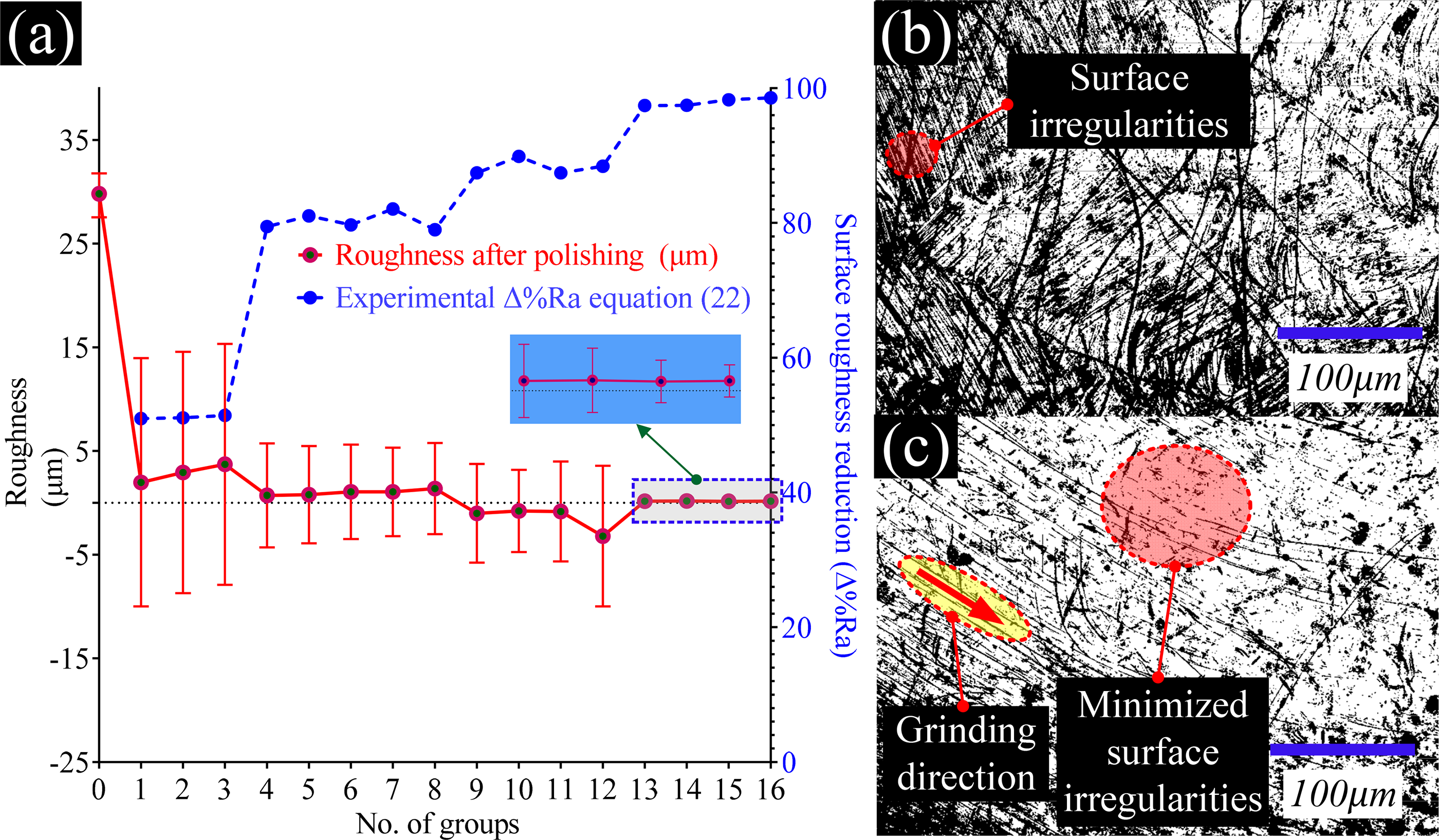
Roughness change after polishing in the small hole region in the first 16 groups of experimentally granting oil nozzles.
Figure 10a shows a clear trend in the change of surface roughness values before and after polishing of the oil granting nozzles under different test conditions. In most of the conditions, the surface roughness values are significantly reduced after polishing, which indicates that the polishing process has a significant effect on improving the surface quality of the oil nozzles. The surface roughness values may have increased slightly after polishing in a very few conditions, but the overall trend still indicates that polishing is effective. Before the polishing process, the nozzle small hole region’s surface roughness is at the range of [27.541,31.789] μm. After the process, this item is reduced to the range of [−0.312,0.508] μm. The above changes in the roughness indicate that nozzle small hole region’s surface roughness is significantly reduced after the polishing and deburring process, which means the feasibility of this study, and to a great extent, it is a good example for the study of the nozzle small hole region surface quality. This implies the feasibility of the study and improves the workpiece surface quality to a great extent. The observations of a spiraling trend in the surface roughness change amount
To further determine the effect of four machining parameters on the oil granting nozzle surface roughness, the polar deviation analysis is carried out on the processing data of the oil granting nozzle in Figure 10a. Through the above steps, finally, the individual factor level mean figure is established, as shown in Figure 11.
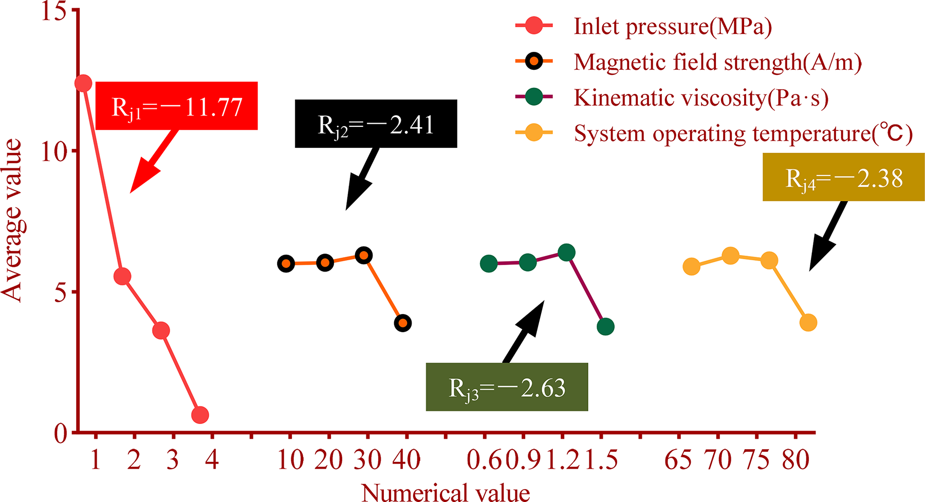
Factor–parameter relationship diagram.
Figure 11 shows the trend of the different factor levels with the values of the corresponding indicators, where the discounted slope expresses the degree of the test influencing factors. When the condition is 40 A/m magnetic field strength, inlet pressure is 4 MPa, kinematic viscosity of the abrasive is 1.5 Pa·s, and the system operating temperature is 80°C, the experimental indicators are at the lowest values. This indicates that the combination has the best processing effect.
The Orthogonal Test ANOVA Table for Grease Nozzle Export Area
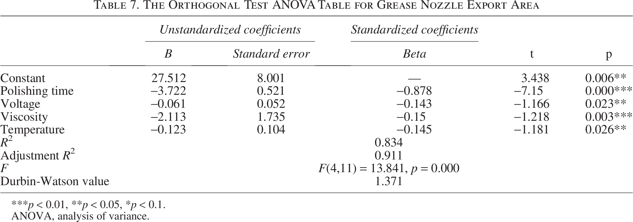
***p < 0.01, **p < 0.05, *p < 0.1.
ANOVA, analysis of variance.
As shown in Table 7, multifactor ANOVA was used to analyze whether different levels of multiple categorical variables had a significant effect on the results. For the variable polishing time, from the analysis of the results of the F-test, it can be obtained that the significance p-value is 0.015**, which shows significance at the level, and there is a significant effect on roughness with a main effect. For the variable viscosity, from the analysis of the results of the F-test, it can be obtained that the significance of p value is 0.042**, which does not present significance at the level, and there is a significant effect on roughness, and there is a main effect. As for the variable voltage and variable temperature, from the analysis of the results of the F-test, it can be obtained that the significance of p-value is 0.166 and 0.172, respectively, which does not present significance at the level, and there is no significant effect on roughness, and there is no main effect. According to the above test results, the order of factors affecting the polishing effect can be summarized as follows: polishing time > abrasive viscosity > voltage > temperature. For surface roughness measurement, a Zeiss Smart Zoom 5 microscope was used in this study. The specific experimental setup is shown in Figure 12.

Roughness acquisition equipment.
Comparative color temperature maps of the roughness change in the oil granting nozzle’s small hole region before and after the machining of sample 17# as well as the change in micromorphology are shown in Figure 13.

Roughness change after polishing in the small hole region of the oil-granting nozzle at experiment 17#.
Figure 13a shows the surface morphology and regional roughness color temperature of the oil granting nozzle before systematic processing for the test 17#. Before processing, its surface texture is complex, and the burr depression situation is obvious, which does not meet the corresponding product process requirements. Figure 13b shows that the small hole region for nozzle’s small hole region surface quality in 17# is significantly improved under the optimal combination of system processing parameters. Through the surface roughness measurement graph, the surface roughness has been reduced to about 0.13 μm after processing. This experiment shows a significant improvement in processing results compared with the 16 sets of orthogonal tests conducted previously.
Conclusion
In the equipment manufacturing industry, the precision machining of metal parts such as inner cavity walls and channels, especially those with complex profiles and high surface quality requirements, remains a technical challenge. To cope with this challenge, the study proposes a processing method with LMP alloy as abrasive. Numerical simulation, parameter optimization, and adaptive prediction are carried out to study a nozzle polishing example, which is made by SLM technology. The main conclusions are as follows:
Based on the characteristics of the media flow channel abrasive flow polishing system and the requirements of the processing object, the study selects In21Sn12Bi49Pb18 LMP alloy abrasive as the system polishing fluid. Based on the temperature characteristics of this abrasive, the appropriate processing temperature is selected to achieve precise polishing control. Aimed at the processing defects and other problems of SLM technology made oil-granting nozzle, the nozzle is used as a media flow channel abrasive flow polishing system processing object. Through CFD numerical simulation, the method of controlling variables is used to add four factors as parameters affecting the processing effect. Aiming at the above four machining parameters, the study designed 16 sets of orthogonal tests on the system for processing the oil-granting nozzle. Before and after the processing of the system, the roughness of the nozzle’s small hole region was reduced from [27.541,31.789] μm to [−0.312,0.508] μm. The processing effect is remarkable. For the orthogonal experimental processing data, the polar analysis method is used. The optimal processing parameters of the system are obtained as inlet pressure of 4MPa, a magnetic field strength of 40 A/m, abrasive kinematic viscosity of 1.5 Pa·s, and system operating temperature of 80°C. The system is then optimized to achieve the optimal processing results. The combination of the above parameters is introduced into experiment 17#. The measurement results showed that the surface roughness is reduced to about 0.13 μm after processing. This process parameter combination has significantly improved the processing effect compared with the 16 orthogonal experiments carried out previously.
Authors’ Contributions
H.P.: Conceptualization, Methodology, Software, Formal analysis, Investigation, Data Curation, Writing—Original Draft, Visualization. Z.Y.: Validation, Resources, Writing—Review & Editing, Supervision, Project administration.
Footnotes
Author Disclosure Statement
No potential conflict of interest was reported by the authors.
Funding Information
No funding was received for this article.
Data Availability Statement
The data that support the findings of this study are available from the corresponding author upon reasonable request.