
Abstract
Sub-nanosecond pulsed electric fields (sub-nsPEFs) present a promising tool for cellular and intracellular electro-manipulation. In this article, we propose a microfluidic device based on a coplanar waveguide (CPW) for high-intensity sub-nsPEF delivery and biomedical investigations. To deliver high-intensity and ultra-short-duration pulses, the CPW device features a miniaturized gap width of 345 µm. Numerical simulations and measurements confirm that this device presents a return loss lower than −10 dB over a wide frequency bandwidth, up to 3.7 GHz. Additionally, the results demonstrate a consistent electric field homogeneity within the CPW channels, particularly in the central area where the biological samples will be exposed. The CPW-based device was characterized under high-voltage sub-nanosecond duration pulse exposure. The results evidenced that the device is suitable for the delivery of ∼18 MV/m intensity and 500 ps duration pulses.
Keywords
Introduction
The bioelectric discipline has seen remarkable growth, particularly in the last century with the discovery of electroporation and its groundbreaking applications in biomedicine for cancer treatment.1,2 Electroporation is a biological phenomenon that induces temporary permeability modification in cell membranes. This phenomenon occurs when applying pulsed electric fields (PEF) of short durations in the microsecond to millisecond range and high intensities around several thousands of V/cm.2–4 Electroporation allows molecules exchange between the extracellular and intracellular environments, opening the way for several potential biomedical applications such as cancer treatment using electrochemotherapy, gene transfer, or pulsed field ablation.5–7
Besides cellular electropermeabilization, exposure of biological cells to pulses with nanosecond and sub-nanosecond duration (nsPEF and sub-nanosecond pulsed electric fields [sub-nsPEFs]), and with electric field intensities reaching tens of MV/m, have induced bio-effects through cellular and intracellular components.8,9 Literature cites effects such as apoptosis, or death, through mitochondrial-mediated pathways and endoplasmic reticulum stress.10,11 The application of sub-nsPEF is thus considered as a promising tool, particularly for intracellular electro-manipulation.12–14 The ability of sub-nsPEF to induce fast and precise effects such as ion channel and protein modulation using intensities below electroporation thresholds is also presently researched. 15 The investigation of nsPEF and sub-nsPEF effects requires specific exposure systems, including high-voltage pulse generators and delivery systems for an optimal transfer to the biological samples. 16 Sub-nanosecond duration pulses with fast rise times are characterized by wide frequency bandwidths attaining large spectra of a few GHz. Consequently, for an optimal pulse exposure, the pulse generator and the delivery system should be impedance-matched over the entire frequency bandwidth. The design of delivery systems with GHz-bandwidth that are compatible with high electric field intensities and direct contact with the biological sample remains challenging.
In literature, only a few devices were developed for in vitro high-voltage nsPEF (∼3 ns) and sub-nsPEF experiments. The classical electroporation cuvette, consisting of two parallel metallic electrodes of rectangular shape and extensively used to apply pulses (microsecond to millisecond range),17–19 was also adapted for the nsPEF and even sub-nsPEF exposure. For instance, an electroporation cuvette with a 4-mm gap distance was employed for the delivery of pulses with 10 ns duration and electric field intensities varying from 5 MV/m to 1.25 MV/m. 20 A similar electroporation cuvette was used to apply, on a low conductance medium, pulses with 600 ps duration and intensity reaching up to 6 MV/m. 21 A common device architecture,22,23 is based on two parallel wire electrodes enclosing the biological sample. This type of device generates a uniform electric field and allows real-time visualization of the samples during exposure. A stainless steel wire electrode pair separated by a 330 µm gap was used to deliver unipolar, bipolar, and delayed bipolar 10 ns pulses with an electric field intensity up to 11.5 MV/m. 22 Thin tungsten wire electrodes separated by a 200 µm gap were used to apply 2.5 ns and 5 ns pulses with an intensity of 10 MV/m. 23 Despite their efficiency for nsPEF delivery, the electroporation cuvette and wire electrodes are limited for sub-nsPEF application due to their bandwidth of a few hundreds of MHz. Microfluidic systems integrating micro-sized channels where fluids or/and cells circulate allow combining high-intensity pulse delivery and miniaturized devices. Indeed, miniaturized structures, typically through small electrode spacing, require lower incident voltage levels to generate a stronger electric field in comparison with classical PEF exposure systems. A grounded coplanar waveguide based on insulated electrodes with capillary tubes separated by a 1 mm gap was reported. 24 The samples contained in capillary tubes were exposed to pulses with 260 ps duration and a rather limited electric field intensity of 0.914 MV/m. 24
In this article, a new microfluidic delivery system based on a coplanar waveguide (CPW) transmission line dedicated to in vitro exposure of biological samples to high-intensity sub-nsPEF is proposed. Previous microfluidic electroporation chambers often exhibited limited bandwidth due to inherent physical constraints. Parasitic capacitance between electrodes and surrounding structures, inductive effects from interconnects, impedance mismatches at interfaces, and dielectric properties frequency variation of biological mediums collectively restrict the efficient transmission of high-frequency pulses. These factors cause signal distortion, attenuation, and reflections, which degrade pulse shape and reduce the effectiveness of ultrafast electroporation protocols. Addressing these limitations is critical for enabling reliable delivery of sub-nanosecond pulses, motivating the design of the present CPW-based microfluidic system. The performance of the CPW-based delivery system was assessed through numerical simulations using 3D electromagnetic software and experimental frequency and time domain characterizations.
Materials and Methods
Coplanar waveguide (CPW)
The aim of this work is to design a wide-band delivery device able to apply high-intensity sub-nsPEF to biological samples. For optimal pulse transmission, impedance matching of the delivery system, typically 50 Ω, within the pulse frequency bandwidth is required (e.g., up to approximately 2 GHz for a 500 ps pulse).
To apply high-intensity and large-bandwidth sub-nsPEF, a coplanar waveguide technology
25
was adopted for the design of the delivery system. Classical CPW transmission lines offer impedance matching over large frequency bandwidths (up to a few GHz). A CPW transmission device is composed of a substrate sustaining a central signal line and two external, grounded lines. Besides supporting microscopic observations, this versatile topology produces higher electric field intensities by reducing the gap between the lines. Indeed, the electric field intensity is proportional to the voltage amplitude and inversely proportional to the gap distance between electrodes in accordance with equation:
Our methodology consisted of designing a CPW that is impedance-matched. While the initial geometry of the CPW was based on existing analytical equations of air-filled channels for first prototyping purposes, subsequent simulations and impedance optimization were conducted assuming the microfluidic channels were filled with the biological culture medium. Given its frequency-dependent high relative permittivity and bulk conductivity, the biological medium significantly influences the electromagnetic properties of the structure, including the characteristic impedance. Incorporating the dielectric loading into the model was essential to ensure proper impedance matching and realistic electric field distributions during operation. This step was critical for achieving efficient pulse delivery and minimizing signal reflection at the interfaces. The CPW dimensions were therefore adapted to maintain the impedance matching in the presence of the culture medium, implying higher characteristic impedance for the air-filled model. Initial dimensions, including the central line width (
CPW-Based delivery ystem design
The designed CPW-based delivery system is shown in (Fig. 1). It consists of a printed circuit board (PCB) composed of a 0.5 mm-thick FR-4 substrate with a dielectric permittivity
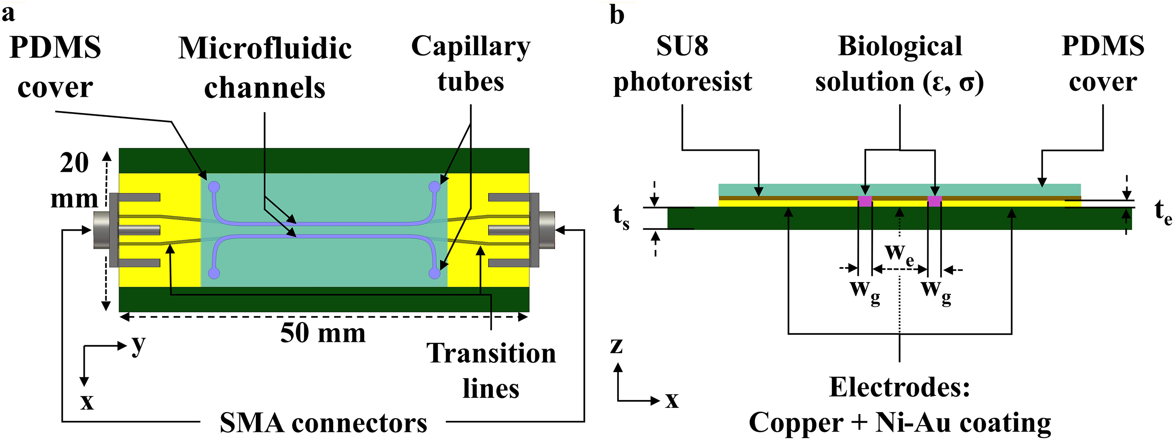
CPW-based delivery system geometry and components.
To guide the biological medium, microfluidic channels were fabricated using a 10 µm-thick SU-8 photoresist resin (
Numerical simulations
Numerical simulations were conducted using full-wave 3D EM software, i.e., CST Microwave Studio with the finite-integration technique (FIT) solver. The CPW delivery system was modeled with the geometrical dimensions, materials, and dielectric parameters indicated in the previous section. SubMiniature Version A (SMA) connectors were modeled with perfect electric conductors and with polytetrafluoroethylene insulator. The feeding input source and the output load were modeled by waveguide ports. The CPW gaps, i.e., the microfluidic channels, were filled with Dulbecco’s Modified Eagle Medium (DMEM), a widely used cell culture medium. 27 DMEM electrical parameters, i.e., permittivity and conductivity, plotted in (Fig. 2), were extracted from experimental measurements performed on a DMEM sample using a dielectric probe (85070E Dielectric probe kit, Agilent, Santa Clara, CA, USA) connected to a vector network analyzer (HP 8753E, Agilent, Santa Clara, CA, USA). For accurate computations, the measured medium’s electrical parameters were implemented in the numerical simulation versus frequency.
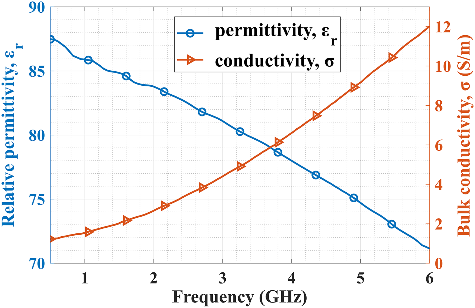
DMEM culture medium measured electric properties: relative permittivity (circle) and bulk conductivity (right-pointing triangle). The electric properties measured data were measured with a VNA over 6 GHz frequency bandwidth and were implemented in the simulation for more accurate computations.
The experimental pulse waveform generated by the high-voltage generator was imported as the FIT solver excitation signal. To ensure a good compromise between accuracy and simulation time, the CPW microfluidic channels containing the biological sample were nonuniformly meshed with a finest and coarsest grid resolution of 1 μm and 440 µm, respectively. A typical simulation volume comprised 833 × 130 × 89 unit cells for a total computing memory size of 7 GB and a simulation time of 29 h on a computer equipped with an Intel Xeon E5-1620 v0 CPU 3.60 GHz and 32 GB of RAM.
Fabricated CPW-based delivery system
The PCB of the fabricated CPW-based delivery device prototype, shown in (Fig. 3), was commercially manufactured. The microfluidic channels were implemented by laser photolithography within the technological platform of our research institute. Capillary tubes, with ∼0.3 mm inner diameter, were inserted into the fluidic inlets of the PDMS cover. Biological samples were injected into the tubes through the inlets using a syringe pump. The medium volume that could be injected in both channels was computed as 0.646 µL. The dead volume associated with the fluidic tubing and connectors was estimated to be 2 µL, minimized by employing short lengths (∼3 cm) of tubing with an inner diameter of ∼0.3 mm.
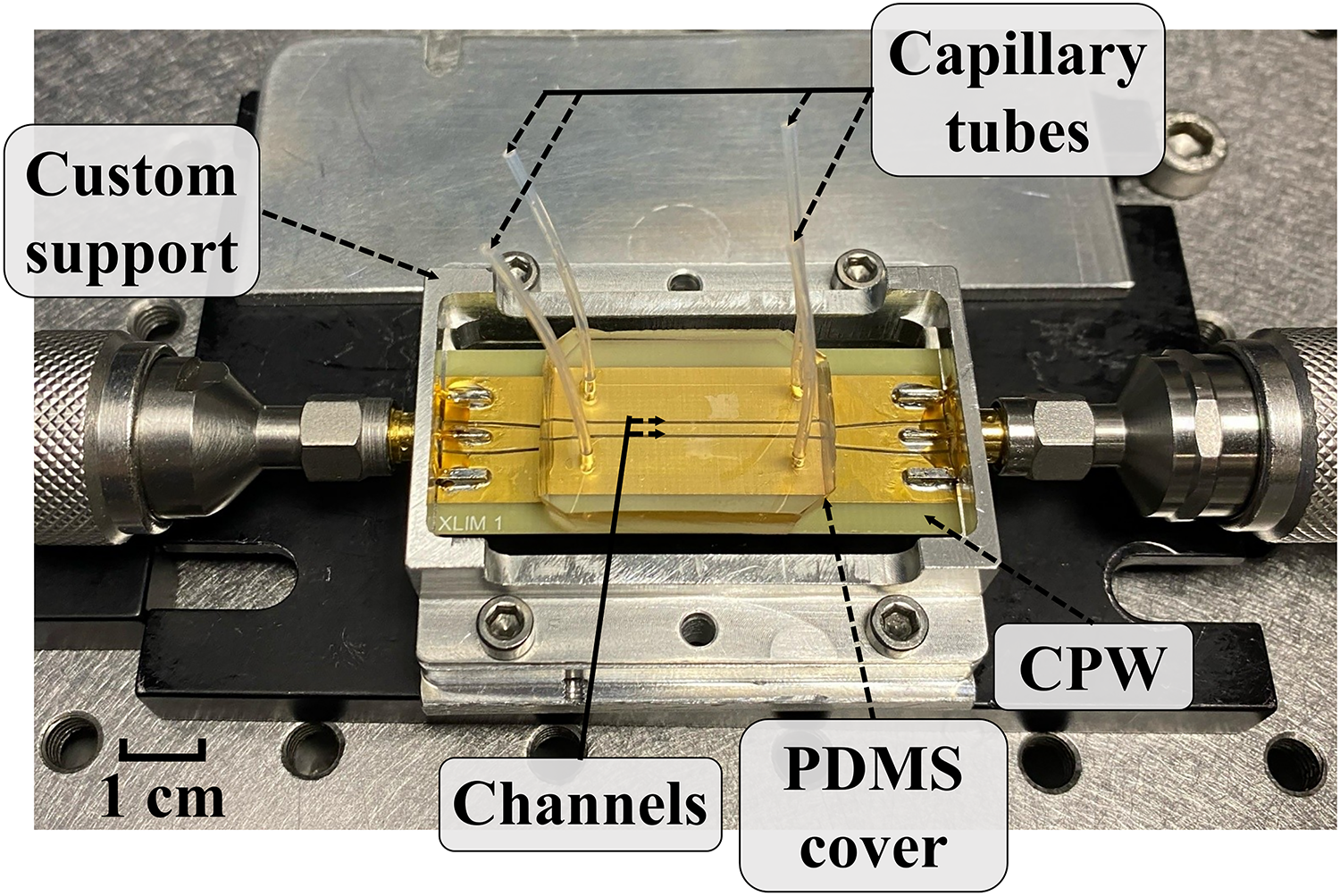
Fabricated CPW-based delivery device connected through SMA connectors to coaxial cables, prototype with PDMS cover on SU-8 photoresist microfluidic channels. Capillary tubes (∼0.3 mm inner diameter) are inserted into the PDMS cover inlets/outlets. A custom support system was fabricated to host the CPW microfluidic device under the microscope and for better monitoring during the experiments.
Frequency electromagnetic characterization setup
The CPW delivery system was frequency characterized through measurements of scattering Sij parameters, i.e., reflection and transmission coefficients. As illustrated in (Fig. 4a), Sij parameters were measured by connecting the CPW delivery system to a vector network analyzer (HP 8722D, Agilent, Santa Clara, CA, USA) presenting a 50 Ω test port impedance. Two configurations were measured up to 5 GHz depending on whether the microfluidic channels of the CPW delivery system were filled or not with the culture medium.

Schematic of measurement setups.
Time domain measurements setup
The high-voltage experimental setup is presented in (Fig. 4b). The setup relies on a custom-built pulse generator based on a pulse-forming network featuring two photoconductive semiconductor switches (PCSS). This type of generator architecture was described in the literature.28–30 The transient photoconductivity within the PCSSs was triggered by a 1064 nm, 35 ps, Q-switch Nd:YAG laser (PL2251A, Ekspla, Vilnius, Lithuania). The generated electrical pulses exhibited a width of 500 ps, a rise-time of about 80 ps, and an amplitude up to 10 kV across 50 Ω, i.e., 20 kV across an open load. A 3-port high-voltage tap (245-NMFFP-100, Barth Electronics, Inc., Boulder City, NV, USA), also denoted as “tap off,” was inserted between the generator and the CPW to observe the incident and reflected waves on a high-speed, 8 GHz, 20 GS/s, oscilloscope (TDS6804B, Tektronix, Beaverton, OR, USA). The transmitted voltage pulses were acquired by the oscilloscope through a 50 Ω high-voltage attenuator (142-GHMFP-26 B, Barth Electronics, Inc., Boulder City, NV, USA).
CPW-Based Delivery System Capabilities
Frequency bandwidth characterization
Reflection (S11) and transmission (S21) coefficients obtained from simulations and measurements are presented in (Fig. 5). A good agreement between simulated and measured results is observed on both Sij parameters. As shown in (Fig. 5a), |S11|dB is lower than −10 dB up to 3.7 GHz. This is a typical threshold used to assess a system frequency bandwidth. Indeed, a −10 dB reflection coefficient level means that 10% of the incident power at the delivery system input is reflected due to impedance mismatch losses. The transmitted power, given by the transmission coefficient (S21), is delivered through the CPW system or dissipated within the dielectric materials, such as the biological sample or the PCB substrate. As shown in (Fig. 5b), the transmission coefficient |S21|dB is higher than −3 dB up to 2.2 GHz, corresponding to 50% transmitted power. Therefore, when combining optimal impedance matching (S11) and transmission (S21) results, the delivery system frequency bandwidth is approximately 2 GHz, which is consistent with the delivery of 500 ps pulses.

Simulated (circles) and measured (right-pointing triangles) S-parameters of the CPW-based delivery system, channels filled with DMEM culture medium.
Further electrical investigations were conducted using time domain reflectometry (TDR). TDR is a standard procedure for characterizing transmission lines, as it allows locating and measuring impedance discontinuities.
31
Its principle relies on observing the reflected voltage waveform
Experimentally,

As a first approximation, without considering the losses, the multiple internal reflections and the transformer effect, one can estimate the transmission line characteristic impedance Zc as a function of y position of the CPW in (Fig. 1):32,33
Electric field distribution
The electric field distribution along the CPW delivery system was extracted from the CST simulation. The excitation signal defined in the simulation corresponds to the experimentally generated pulse waveform shown in (Fig. 6) with 8 kV maximum amplitude. The maximum electric field within the structure is illustrated in (Fig. 7) and (Fig. 8).
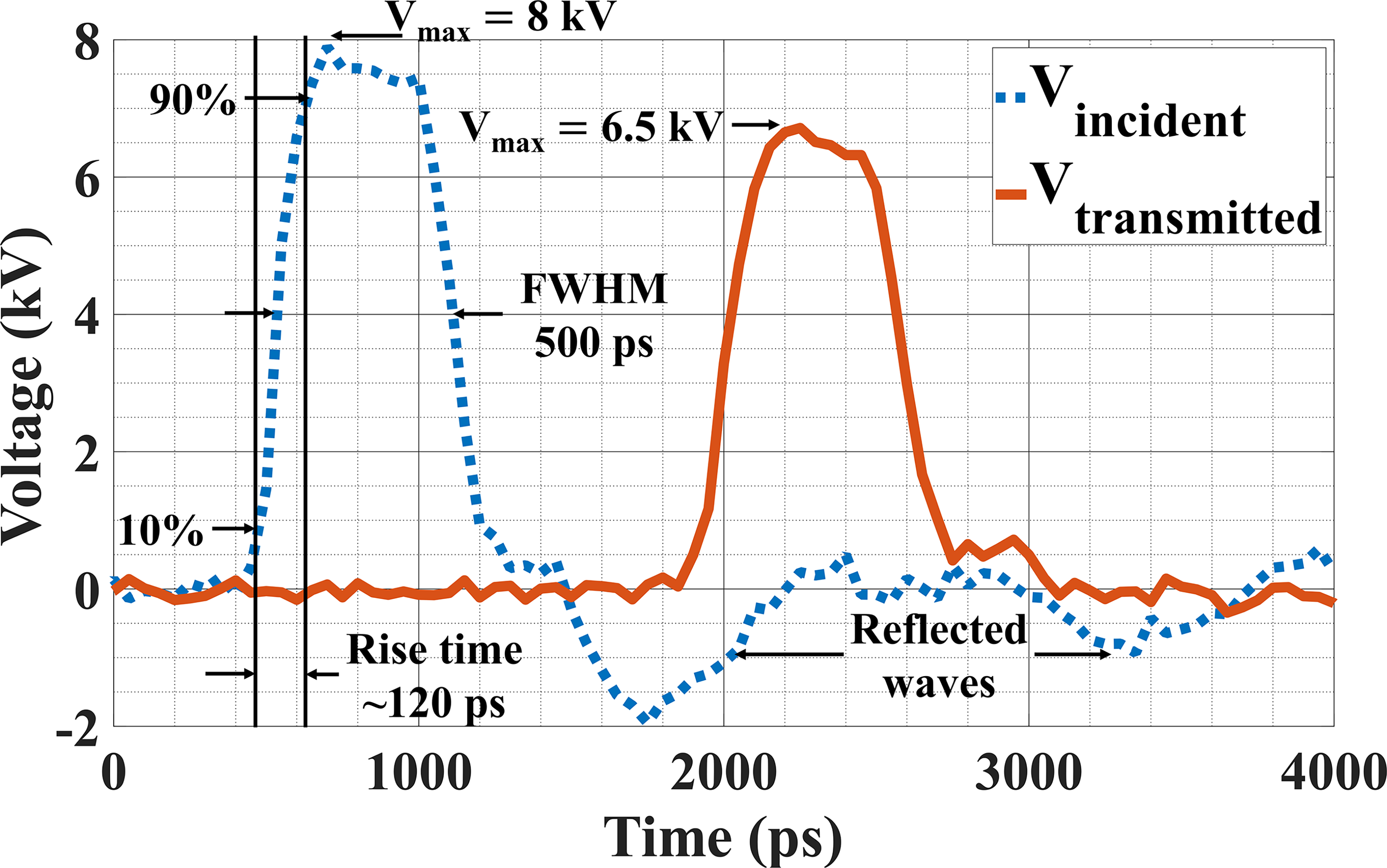
Incident and transmitted voltage pulses measured in the input and output of the CPW-based delivery system containing DMEM culture medium. Measurements were performed using a high-speed, 8 GHz, 20 GS/s, oscilloscope.

Electric field values along the CPW channel width (345 µm) between the electrodes (x axis), filled with DMEM culture medium, extracted at maximum electric field position.

Electric field distribution extracted from numerical simulations along the CPW structure loaded with DMEM culture medium. Top view (XY plane) illustrating the field along the CPW length, cross-sectional view (XZ plane) showing the field across the CPW width, magnified view of the CPW channel region. The color scale represents the electric field magnitude in MV/m. Simulations were performed using an excitation signal corresponding to the experimentally generated pulse waveform (500 ps of duration, 8 kV of voltage magnitude).
The results demonstrate good electric field homogeneity along the width, length, and height of the CPW’s channels. Higher electric field values are observed in the vicinity of the electrodes due to the edge effects. However, a uniform electric field with an approximate intensity of 18 MV/m is obtained in the center area within the channels where the biological sample are exposed through a laminar flow.
High-voltage experimental results
The application of high-voltage sub-nsPEF using the CPW-delivery system was characterized using the experimental setup shown (Fig. 4b). Incident, reflected, and transmitted pulse waveforms measured at the input/output of the CPW-delivery system, containing DMEM culture medium, are presented in (Fig. 6). The incident pulse magnitude, duration and rise time were 8 kV, 500 ps, and 120 ps, respectively. Compared to the incident pulse, the results indicate that although the transmitted pulse duration, and rise time were preserved, the voltage decreased to 6.5 kV. This 18.7% voltage decrease can be attributed to the reflected waves resulting from the mismatch losses and to the power dissipation within the CPW device. In accordance with the numerical results (Figs. 7 and 8) and considering the losses, the biological sample is exposed in this configuration to an approximate 18 MV/m electric field intensity.
To better contextualize the advances of our work, a summary table comparing key performance metrics, including pulse durations, bandwidths, achieved electric field strengths, type of device of our CPW delivery system and literature reported studies21,24,34–37 (Table 1).
Quantitative Comparison Study of Electroporation and Planar Fluidic Nanosecond and Sub-Nanosecond Devices Including Pulse Durations, Bandwidths, Achieved Electric Field Strengths, Type of Device

Discussion
Electrodes biocompatibility and electrochemistry
While gold is generally considered inert and biocompatible, the application of high-voltage monophasic pulses can still induce electrochemical reactions at the electrode–electrolyte interface. These reactions may result in localized pH shifts, generation of reactive species, and the release of metal ions into the surrounding medium. Such effects are typically minimal in macroscale electroporation systems due to the large buffer volume, which dilutes reaction byproducts. However, in microfluidic environments where the electrolyte volume is small relative to the electrode surface area, these side effects can be significantly amplified. This can impact both the local cellular microenvironment and the long-term biocompatibility of the system. Although our current work focuses on system design and pulse delivery performance, these electrochemical considerations are crucial for future biological applications. Potential mitigation strategies may include the use of biphasic pulses, protective electrode coatings, or continuous perfusion of fresh buffer during stimulation. These aspects will be explored in future studies as the system is further adapted for live-cell experiments.
Suitability of the CPW for in vitro cellular studies
Although the present work focuses on the design and electrical characterization of the device, its intended use in future biological experiments may involve suspended or adherent cells. To support robust cell adhesion within the chamber, appropriate surface treatments can be applied. Common strategies include coating the substrate with poly-L-lysine, fibronectin, or Matrigel to promote attachment of specific cell types. 38 The choice of coating will depend on the cell line used and must be optimized to ensure both adhesion and compatibility with the applied electrical fields.
Electric field strengths considerations
Ultrashort pulse electroporation (∼500 ps) typically requires higher electric field strengths. Extrapolations suggest fields near 100 MV/m may be necessary for effective membrane permeabilization at this pulse duration. However, the literature reports 14 that PEFs with durations ranging from 200 to 800 ps and field strengths between 0.914 MV/m and 95 MV/m can still trigger significant cellular responses. Notably, even at the lower end of this range, around 0.914 MV/m, an increase in cytosolic Ca2+ concentration has been observed following PEF exposure. 24 With a 345 µm electrode gap, this corresponds to theoretically applied voltages of approximately 35 kV. Considering dielectric breakdown, the CPW is fabricated on an FR4 substrate with a relative permittivity of 4.4 and a loss tangent of approximately 0.02. These substrate parameters influence the characteristic impedance and the dielectric losses at high frequencies but also set constraints on the maximum voltage and field that can be safely applied before dielectric breakdown occurs. Typical dielectric breakdown strength of FR4 is on the order of 20 MV/m, while that of DMEM solution lies in the range of 20 to 30 MV/m. Therefore, the effect of sub-nsPEF breakdown in dielectrics liquids is an important factor to consider, as it could impose practical limitations. 39 However, this must be considered in light of the pulses duration. To the best of our knowledge, for pulse durations around 500 ps, these effects have not been limiting so far, unless a very large number of pulses are applied at high repetition rates.
Conclusion
A wide-band CPW-based delivery device was designed, fabricated, and characterized under high-voltage sub-nanosecond duration pulse exposure. To deliver high electric fields intensities (>10 MV/m), ultra-short duration pulses (500 ps), a miniaturized gap width (345 µm), and line metallization thickness (21 µm) were considered for the CPW-based microfluidic device. It was demonstrated by frequency measurements that this device presents a 3.5 GHz frequency bandwidth when considering
Time domain measurements evidenced that the device is suitable for the delivery of pulses in direct contact with the biological samples of 18 MV/m intensity, and 500 ps duration. Further investigations with this CPW-based microfluidic device include exploring higher intensities, pulses shapes, and in vitro biological experiments aiming to study effects on cells such as cellular ion-channel modulation under sub-nsPEF.
Authors’ Contributions
Conceptualization: P.L., D.A.-C., and C.D. Methodology: H.T., L.M., and A.N. Software: A.N. Validation: P.L., D.A.-C., and C.D. Formal analysis: H.T. and L.M. Investigation: H.T. and L.M. Resources: P.L., D.A.-C., and C.D. Data curation: P.L., D.A.-C., and C.D. Writing—original draft: H.T. and L.M. Writing—review and Editing: P.L., D.A.-C., and C.D. Visualization: H.T. and L.M. Supervision: P.L., D.A.-C., and C.D. Project administration: P.L., D.A.-C., and C.D. Funding acquisition: P.L., D.A.-C., and C.D. All authors have read and approved the final article.
Footnotes
Acknowledgment
The authors would like to thank the Nouvelle Aquitaine council and the European Union under the PILIM program for funding this work and the Platinom platform for the support.
Author Disclosure Statement
The authors declare having no conflict of interest or competing financial interests.
Funding Information
This work was funded by Region Nouvelle-Aquitaine under contract AAPR2022A-2021.