
Abstract
iLoc is an ultrasound ranging based indoor localization system deployed at the iHomeLab at Lucerne University of Applied Sciences and the Embedded Systems Lab at Stuttgart University of Applied Sciences. The system tracks humans in AAL scenarios which bear an ultrasound transmitter for example in the form of a name badge. The transmitter can be localized with an average accuracy well below 1 meter, by means of wired reference nodes distributed in the lab rooms. A small battery may suffice for several month of transmitter operation. The original deployment consists of wired nodes. Data and power is supplied via the IPoK fieldbus. Configuration data, i.e. node positions, are measured manually and entered in a database. The system participated at the first EvAAL competition 2011 and reached best accuracy score. iLoc+, A modified system comprising battery powered wireless nodes and an automatic configuration procedure was used at the second EvAAL Competition 2012. Both solutions are compared with focus on obtained accuracy and installation effort, using data from the respective competitions. Results of the comparison are discussed and possible optimizations are outlined. The implications may also be relevant for other positioning technologies in the AAL sector.
Keywords
Introduction
Ultrasound time-of-flight measurement is a proven technology for indoor ranging and has already been successfully applied to indoor localization systems in the past. Prominent ultrasound based localization projects are for example the “CRICKET”, “CALAMARI” and “BAT” systems ([1–3]). They provide high and reliable accuracy, achieved with moderate effort. Starting from this proven technology, the iLoc system and its successor, the iLoc+ variant has been developed. The iLoc system successfully competed at the EvAAL Competition 2011 [4,5] on indoor localization. Lessons learned among others at this competition led to a modified setup, referred to as “iLoc+”. The new “iLoc+” system was employed during the localization track of the EvAAL 2012 [6,7] competition. In Sections 2 and 3 an overview on the systems is given. In Sections 4 and 5 the deployment and the results of the systems at the competition are presented and discussed. Section 6 compares the different approaches with respect to the evaluation criteria of the competition and with respect to own findings during competition preparation and negotiation. In the concluding Section 7 influence of the results on further developments of iLoc are outlined and it is discussed if some results have general applicability to indoor localization systems in the AAL field.
The iLoc system
Overview
The iLoc ultrasound ranging based indoor localization system (Fig. 1) comprises badges, detector nodes and a position server, as well as network infrastructure. The badges are carried like name tags by persons and their position is detected and tracked by the system. The system can be installed with moderate effort by a trained person within some hours. The receivers may not be hidden behind walls etc. to allow line-of-sight sound propagation to at least 3 receivers. Besides that the system is not affected for example by a change of the placement of furniture. Also there is no degradation of accuracy over time. Position data can be accessed by other applications via a socket interface.
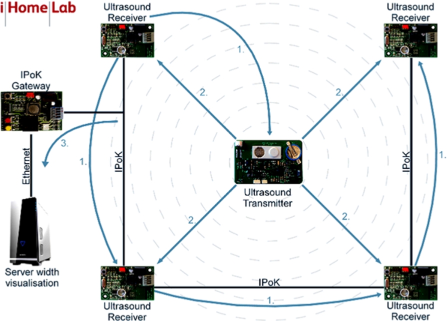
Setup overview: Four reference nodes are shown. The upper left receiver sends out a synchronization signal (arrows labeled “1”) by wire (“IPoK”) to the other reference nodes and by radio to the mobile node (center). The mobile node emits an ultrasound pulse (arrows “2”) and the reference nodes record the reception time.
The name tags (Fig. 2) are equipped with a microcontroller, a radio transceiver and an ultrasound transmitter. They emit ultrasound pulses at a configurable rate, for example 2 Hz, with a duration of 1 ms. These pulses are received by some of the detectors.
The detector nodes, also called reference nodes, are located at known fixed positions. They comprise a microcontroller and an ultrasound receiver as well as a 2-wire network connection to exchange data and time synchronization information. The nodes record the reception times of ultrasound bursts transmitted by the badges and transmit this information to an IP gateway via the 2 wire bus (“IPoK”, [8]). A server calculates position estimates from the received data by multilateration. In the iHomeLab, the position data is used among others for visualization of visitor positions (see Fig. 3). An overview of some iLoc features is described in [9].
A more detailed system layout is sketched in Fig. 4: The detector nodes are combined in groups of 10 .. 15 devices (4 each drawn in the figure) to form one IPoK segment, linked with a “foxboard” embedded linux system to an ethernet infrastructure. Position calculation takes place at the iLoc server, from where the data is accessed by applications, for example the visualization. Synchronization and communication with the interactive badges is decoupled from the iLoc server and performed by a dedicated communication server, to increase reliability of the system.
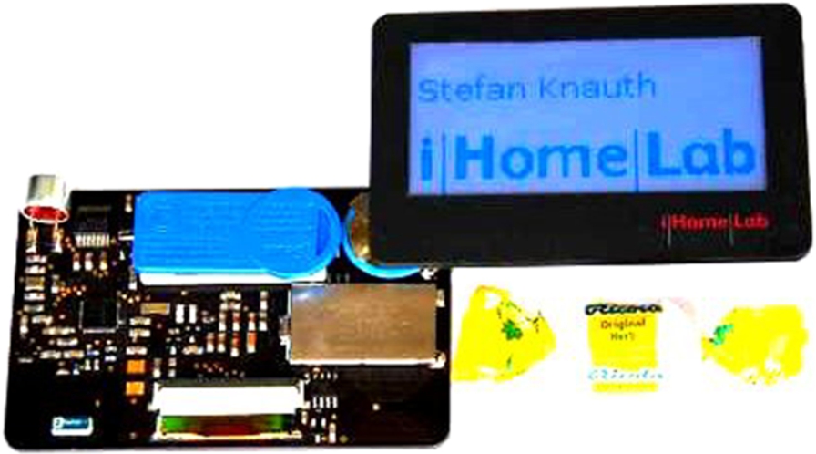
Name badge with IEEE802.15.4 radio transceiver, ultrasound transmitter and LCD.

3D visualization of visitor positions in the iHome Lab. The positions are given as “hovering” cubes indicating the name of the badge bearer, embedded in a 3D visualization of the iHomeLab.
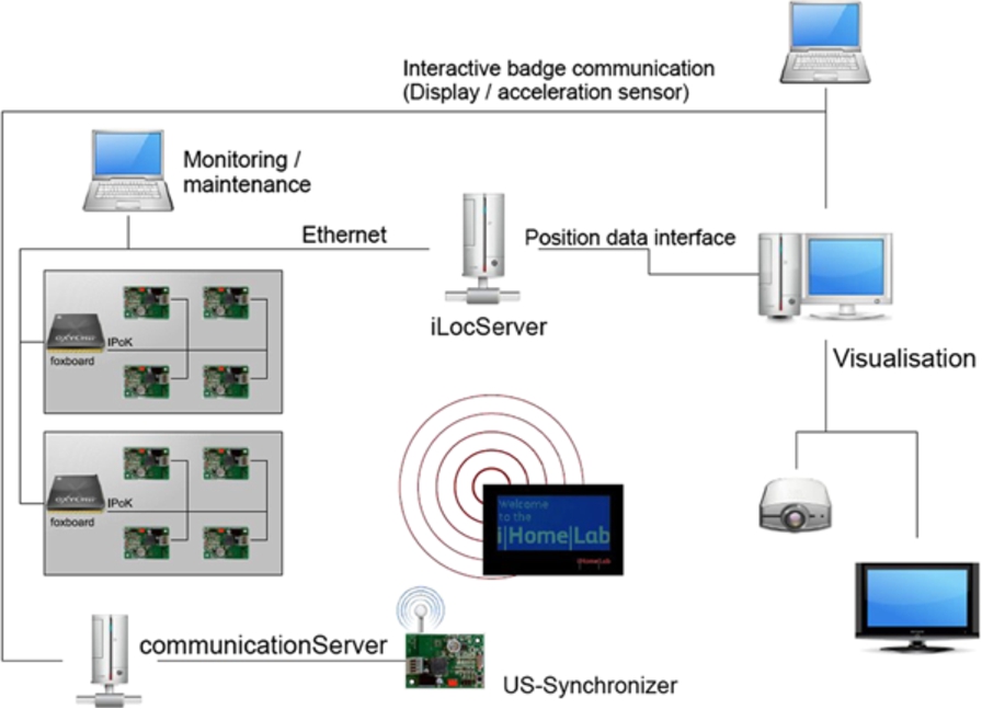
System architecture: a badge, which is carried by the person to be localized, emits an ultrasound burst. Reference nodes measure reception times and send them via IPoK to ethernet gateways labeled “foxboard”. From there they are sent to the iLoc server. The server calculates the badge positions and offers a position data interface, which can be queried by remote applications. In the figure, a visualization client uses this interface. The badges and the receiving nodes are synchronized by the US-Synchronizer. This Synchronizer additionally implements a bidirectional communication link between the badges and interested applications, allowing sending of text to the badges LCD display and reading of acceleration- and battery state from the badge. The link is relayed by the optional communication Server.
Interactive badges
The interactive badge (Fig. 2) comprises the following hardware blocks: a CC2430 Texas Instruments microcontroller including IEEE 802.15.4 radio transceiver, antenna and HF matching network, a Bosch SMB380 triaxial acceleration sensor, a charge pump chip to generate a higher voltage (20 V) to drive the 40 kHz piezoelectric ultrasound transducer, the transducer itself, the LCD unit, a rechargeable 25 mAh lithium battery as well as an inductive charging circuity. The power consumption of the badge hardware is in the range of 1 .. 10 µW in standby mode and raises to about 50 mW in operational mode, with transition times <1 ms. The microcontroller comprises a 32 kHz crystal-based wake up timer.
The LCD carries its own controller and is connected with a serial interface. Power of the display can be switched off by the microcontroller, while the content of the display remains visible. It has been observed that, depending on the environmental conditions (temperature, vibrations), the display content may actually decline. Therefore a display refresh should occur from time to time, for example once a day. Display- and g-sensor related data communication is carried out between the badges and the communication server by listening and answering to synchronization radio packets which are described later.
The badges are equipped with an inductive battery charging circuity, comprising a coil (part of the PCB layout), a rectifier and overvoltage protection. The badges are charged when put into their storage box, without the need to establish any electromechanical connections, for example by plugs or contacts. The storage box comprises two charging coils operating at a frequency of 125 kHz.
Reference nodes
The reference nodes are line-powered and minimal power consumption is not as crucial as for the badge. On the other hand, a large number of these devices have to be deployed and therefore installation and wiring shall be as easy as possible. Therefore the design is considerably different from that of the badges, notably is for example the use of a different microcontroller. The reference nodes comprise a Freescale HCS08GB60 Microcontroller.
For communication between the nodes, “IPoK” (IP over Klingeldraht) has been chosen. It is a protocol for easy networking of small (in size and cost) embedded devices, developed by the authors. The idea behind IPoK is to use a 2 wire multipoint connection as for example RS485, and also supply power via the lines. The IPoK bus carries a 7 .. 30 Volt supply, which is decoupled from the lines by inductors and then converted to 3.3 Volts with a DC-DC converter. The data TX signal is directly coupled in from the Microcontroller. The HCS08 series of controllers offer a 20 mA line driver for the included UART such that the controller can directly drive the line via a capacitor. When not sending, the UART line can be switched to high impedance and no external driver is necessary. For RX, the signal is AC coupled to a comparator or even easier to a pair of standard HC14 Schmitt-Triggers. This leads to a minimum hardware effort for the bus interface circuity.
Operation, timing and synchronization
The maximum detection range of the iLoc ultrasound signal is about 15 meters corresponding to a maximum ultrasound pulse “livetime” of less than 50 msec. This live time is given by the transmitter ultrasound amplitude, the sound path loss, and the receiver sensitivity, and is a consequence of the specific iLoc device parameters and the used sound frequency of 40 kHz.
There exist several design approaches for ultrasound localization systems with multiple mobile nodes. It is important to avoid ultrasound interference between the nodes (see for example [1]). One commonly used approach is to let the fixed infrastructure emit the pulses and send radio packets identifying the sending node. This has some advantages, for example privacy. The mobile node can detect its position without the system knowing that the mobile node exists. Also the number of mobile nodes is not limited in this case as they are passive. A disadvantage of this approach is that the mobile node has to listen for a certain time to radio and sound messages before being able to detect its position.
Operational times of the iLoc transmitter badge for different battery capacities
Operational times of the iLoc transmitter badge for different battery capacities
The central synchronization radio signal is also used by the mobile nodes (name badges) for synchronization. To achieve a synchronization accuracy of about 50 µs, the mobile nodes need to resynchronize every 2–5 seconds. Actually the operation is as follows: The synchronization signal is sent with the slot rate, i.e. every 50 ms, containing also the number of the badge that shall send a pulse in the current slot. For
Basically, 3 range measurements from 3 different reference positions allow the determination of the tag position. Given the above mentioned 15 meter iLoc maximum ultrasound range, these conditions would be fulfilled for example by deploying the reference nodes in a lattice with a spacing of about 10 meters. Practically, depending on the desired accuracy, the density of reference nodes should be much higher such that the distance to the furthermost node does not exceed approximately 5 meters. Then every point in the room is in the ultrasound range of more than 5 reference nodes, increasing the stability of the system against ultrasound interference for example by noise emitted from machinery or people. The ultrasound signal needs a line-of-sight for propagation, which can get lost by a shading caused by the body of the wearer of the tag or by other visitors in the same room. Also reflections have to be taken into account.
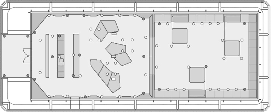
Positions of the 70+ ultrasound receivers in the iHomeLab. The inner gray rectangle indicates the covered area (about 10 m × 30 m). The iHomeLab is located at Lucerne University of Applied Sciences at Campus Horw.
In the lab currently more than 70 nodes are arranged in 6 IPoK bus segments (Fig. 5). Typically an emitted pulse is detected by about 5–15 receivers. Inconsistent range reports are rejected by the multilateration algorithm with a simple but computing intensive procedure: From the reported ranges for all permutations of 3 readings a position value is calculated. By stepwise removing of calculated positions lying outside of the mean value, the most probable readings are selected for the final trilateration [10].
The deployment effort is kept at a reasonable level by using a 2 wire bus system providing power supply and communication to the nodes. Such two wire systems are commonly used for building automation purposes, and are often referred to as “fieldbus”. There exist a variety of standards and vendors. To keep the bus interface hardware on the nodes simple, as mentioned, it has not been opted for an existing fieldbus system but a propriety implementation (“IPoK”) has been employed.
In order to achieve a high accuracy of the system, the positions of the ultrasound receivers need to be accurately determined. Actually only a fraction of the positions have been laser measured. For the remaining positions only estimations have been entered to the database. Then the estimations have been adjusted by reference measurements: A mobile tag (name badge) was placed at a grid of known reference positions and time-of-flight results were recorded by the receivers. The position data of the reference receivers was then adjusted until the measured range values for a particular reference node matched best with the calculated distances. This fitting process was performed by minimizing the sum of the squared differences between measured range and calculated range.
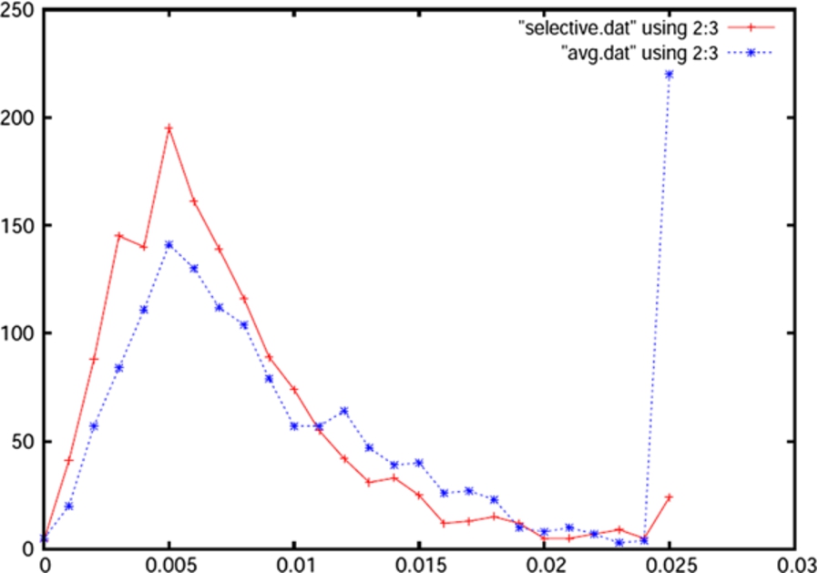
Observed position error in a lab environment after careful adjustment (not the EvAAL setup): dashed line (blue, *) indicates positions which were obtained by multilateration. Solid line (red, +) indicates positions calculated with trilateration and a selection algorithm. X-Axis: error [meters], Y-Axis: number of samples [10].
Using this process, very high accuracy in the 10 cm range has been obtained: Fig. 6 shows data from a set of about 1500 subsequent measurement cycles, with at most 8 out of 9 reference nodes reporting time stamps. The rightmost values include all measurements lying outside of the graphs X-Axis. During the recording of the observations, the sound propagation was intentionally disturbed by noise, i.e. people walking around thereby shielding the ultrasound reflectors. The high overall accuracy of the reported position values (95% within <2 cm) has been achieved by careful determination of the sound velocity and position data of the reference nodes, as described. Under “real world” conditions, the error is typically still be well below 30 cm, provided that the alignment of the nodes has been performed with respective care.

Fall detection application: The name badges transmit acceleration sensor data to the system. In case of a fall, an alert is generated, indicating the location of the incident.
Acceleration sensor data is used by the fall detection application: If the badge measures unusual acceleration values, it reports these values to the system. The fall detection application acquires position data from the iLoc server, analyzes the data and situation and decides whether a fall alert shall be generated. A sample of such an alert screen is shown in Fig. 7. Also long term motion patterns of bearers can be recorded and analyzed to detect unusual behavior of persons like changed wake up time, slower motion speed, etc. which may indicate a medical threat.
In a setup where the system is used in a hospital or a retirement home, context-relevant information may be indicated by the badges display such that a nurse nearby may immediately see relevant emergency medication or illnesses of the patient which may have to be considered in the emergency treatment. Of course, the system may also be used without display, allowing the employment of smaller tags.
Another application in the area of assistance systems is finding of assets. For example, the medicine box, telephone, or glasses may be equipped with an ultrasound tag. If the owner cannot remember where he had placed these things, he may by some modality be informed about the current position of his belongings.

Setup overview: A synchronization transmitter emits timing information via radio channel to the mobile node as well as to the receiver nodes (Node1 .. 3 shown in the image). The mobile node, for example a visitor badge, transmits a synchronized ultrasound burst. The receiver nodes detect the arrival time of this sound burst at their position and calculate the respective time of flights (TOF)
Changes with respect to iLoc
The iLoc+ ultrasound ranging based indoor localization system (Fig. 8) comprises the same mobile nodes (badges, name tags), detector nodes and time synchronization transmitter as the iLoc system. There are two important changes: In iLoc, the reference nodes are transmitting their TOF measurements via a fixed cabling infrastructure, the IPoK bus, which also provides the electric power to the nodes. In iLoc+ the reference nodes are battery powered and transmit their data wireless with a TDMA scheme. Also, as described later, the position of the nodes is not manually determined but detected by an autolocation procedure (see Section 3.3).
iLoc+ reference nodes
The iLoc+ reference nodes use the same hardware platform as the iLoc nodes (see Fig. 9). In the iLoc+ setup they are battery powered and energy consumption is minimized. Three actions have to be performed by the node:
Measurement of the Ultrasound time of arrival Transmission of the TOA data Time synchronization with the central time synchronization transmitter
In the nodes the ultrasound receiver is active at all times, and consumes a considerable current of about 1 mA, which restricts the lifetime to about 2 month, with AA cells. This is because the receiver nodes originally were designed for the older line-powered iLoc system. The remaining parts of the node, namely transceiver and microcontroller, are currently active four times per second, 5 ms each, leading to a duty cycle of 1/50. The four active times per second are used for TOF transmission to the iLoc server and for synchronization. During this active phases the node consumes about 20 mA. The nodes also wake up for a very short time after each time slot, i.e. 20 times per second, to check for- and evaluate TOF data of received ultrasound pulses.

Ultrasound receiver node assembly of battery, PCB and backplate for mounting. The PCB comprises microcontroller, ultrasound amplifier and 802.15.4 radio transceiver.
Positions of the 28 iLoc receivers at CIAMI Living Lab. The nodes are arranged in 3 wiring groups, as indicated in the image.
The manual position determination of the reference nodes can be a time consuming and error prone process. For AAL deployments, low installation costs are important to gain acceptance for a system. A possible automatic reference position determination solution is “leap-frogging” [11], especially feasible for temporary deployments: Here the position of some reference nodes for example at a corner of the deployment area is determined manually. Then a subsequent node is localized by the system using the already localized nodes, and so on. This mode requires the ability to use a given ultrasound transducer of a node not only as receiver, but also as transmitter. Unfortunately this simple approach accumulates positioning errors leading to quite inaccurate positions for distant nodes. More sophisticated algorithms use complex parallel evaluation of all measured node distances (see for example [12] for RF based ranging).
The iLoc+ system uses receivers mounted under the ceiling. The directional propagation characteristics of the used ultrasound transducers favors the indirect transmission path from transmitter to the floor and back to the receiver under the ceiling. Therefore direct observation of the inter-node distance by the nodes themselves is not feasible. The node autolocation procedure for iLoc+ is performed with the help of mobile nodes distributed temporary on the floor. Some of them are placed at known locations, others only help to link together the net of the distance measurements. For the Cricket ultrasound system [12] working autolocation with development of sophisticated algorithms and high obtained accuracy has been described by Mautz and Ochieng [13]. The system currently uses the much simpler multilateration approach of selecting the most “believable” ranges by evaluating all possible permutations of three range readings, as described in this paper (Section 2.4) and more detailed in [10].
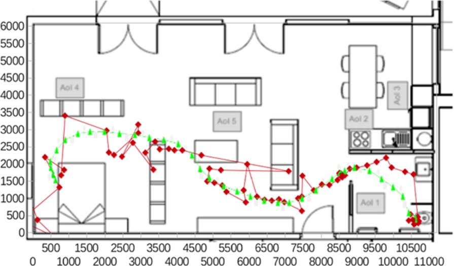
Positions obtained for a specific test during the competition at CIAMI Living Lab. Bright/yellow triangles indicate real path, dark/red diamonds indicate iLoc results. The accuracy was 75 cm for the 75th percentile i.e. 75% of the iLoc obtained values had an error of less than 75 cm.
For the 2011 competition at CIAMI Living lab the original iLoc system with wired nodes was used. For the competition a setup with 28 receiver nodes arranged in 3 IPoK lines has been chosen. This leads to roughly 2.5 m2 coverage per node. It was a requirement that the system had to be installed within one hour. This ruled out the common deployment approach where first the nodes are placed and later the positions of the nodes are determined. Instead, the positions of the nodes were defined prior to the physical installation. Positions where chosen such that they lay in junctions of the lattice structure of the Living Lab ceiling (Fig. 10).
This allowed physical node placing to be performed without having to use any measurement equipment like laser devices or a tape measure. The nodes were placed on certain predefined positions of the ceiling grid, by means of double-sided adhesive tape. Of course, this approach relies on a grid or other alignment structure, which is not normally given in a typical home. The three IpOK lines had been completely commissioned and connected to the receiver nodes already off site. The reader may compare it to, for example, a ready commissioned electric Christmas tree illumination. So no wiring had to be performed on site. The setup time for the system at CIAMI Living Lab was about one hour, and was mainly caused by the taping of the pre-wired nodes and fixation of the IpOK wires.
Accuracy
The score evaluation procedures were defined and published by the EvAAL technical committee, well before the competition run. A summary can be found in [5]. Here mainly the accuracy score is discussed, which comprises a tracking run and an AOI (area of interest) detection. Generally, “accuracy” here refers to the difference between the position of a person moving in the lab as reported by the localization system under test, and the “true” position of the person. Of course that means that the true position of the moving tester is known. EvAAL chose a quite convincing system: The lab floor is marked with a track and reference positions on that track. These positions are accurately determined prior to the competition. A beep signal starts the test run. The tester (for EvAAL there is only one person known to be able to perform this quite accurate :-) walks from one point to the other synchronized by the click of a metronome. The movement and sound is recorded by a video camera for an a-posteriori verification.
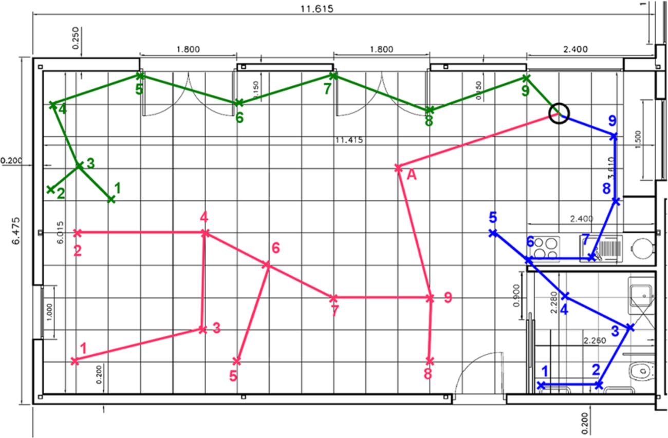
Positions obtained for the AOI detection during the competition at CIAMI Living Lab. 71 percent of the measurements where assigned the correct AOI respectively “no AOI”. The AOIs were squares with a size of 60 times 60 cm. 70% of the reported values where correct, i.e. identified the correct AOI respective “not at AOI”.
The rule for the tracking accuracy is to look at the individual error for each position measurement. This is the distance between the real position and the position reported by the localization system. The overall error is defined as the highest of the lower 75 percent of reported error values. From this overall error value, a score is calculated.
The obtained accuracy score for iLoc was 8.8 which means that 75 percent of the measurements were better than 80 centimeters. A typical result is shown in Fig. 11. The figure indicates that the accuracy performance of the system was quite position-dependent. The walk of the test person starts in the sleeping room. Here the error is above 1 meter. After leaving the sleeping room, the track traverses the living room towards the bathroom. In this phase the deviation from the actual track is well below 50 cm, despite some outlying points which might have been induced by acoustic or electromagnetic noise. The situation changes again when entering the bathroom. Here the path in the room again shows derivations of above one meter, the final position is then detected well.
In order to detect a position value, a minimum of 3 nodes have to receive a direct ultrasound signal. If more nodes receive a signal, the quality of the position reading is increased among others by the ability to detect and ignore reflected signals [10]. The sleeping room and the bathroom were equipped with 4 receivers (Fig 10). As the badge mostly transmits in front of its bearer, it is possible that direct transmission occurs only to two receivers, degrading considerably the performance. The performance in the quite open living area was considerably better since more nodes had line-of-sight with the transmitting badge.
The score for the AOI detection is derived from the ratio “number of correct reports” divided by “total number of reports”. iLoc obtained score was 71 percent, meaning that 71 percent of the measurements where assigned the correct AOI respectively “no AOI”. The AOIs were squares with a size of 60 times 60 cm. Figure 12 allows a qualitative discussion: Most of the AOIs have been detected well. Actually the final AOI positions were slightly different from those indicated in the figure, but still AOI 5 (in front of the sofa) was not detected correctly, and also AOI 6 (the right AOI in the kitchen area) was somewhat shifted. A possible reason could be a misalignment of receivers. In the case of AOI 5, the values were heavily disturbed and spread. This might be attributed to the sound produced by the metronome, which was used to synchronize the movement of the person walking on the path.
The 2012 EvAAL Competition track on indoor localization has been performed at the Smart House Living Lab at ETSIT UPM, Madrid [14]. Details of the general setup and evaluation criteria for the localization track are described in [7], and the technical annex is linked on the EvAAL competition page [6]. A detailed report is given in [15]. iLoc+ uses an autolocation procedure for position determining of the reference nodes. Therefore, these node positions were not predefined but only decided when at the competition site. The positions of the autolocation “master” nodes, however, need to be known accurately. So in a first step 19 positions were marked on the floor of the living lab by tape measure (see Fig. 14 left). These nodes are only necessary for initial calibration, and are removed afterwards, i.e. before the test run. The coordinates of the positions were defined in advance. They were altered where necessary for example if a predefined coordinate was not usable due to furniture. A pre-engineered file containing these coordinates was manually adjusted to reflect the actual 19 calibration positions. Calibration transmitters were placed on the positions.
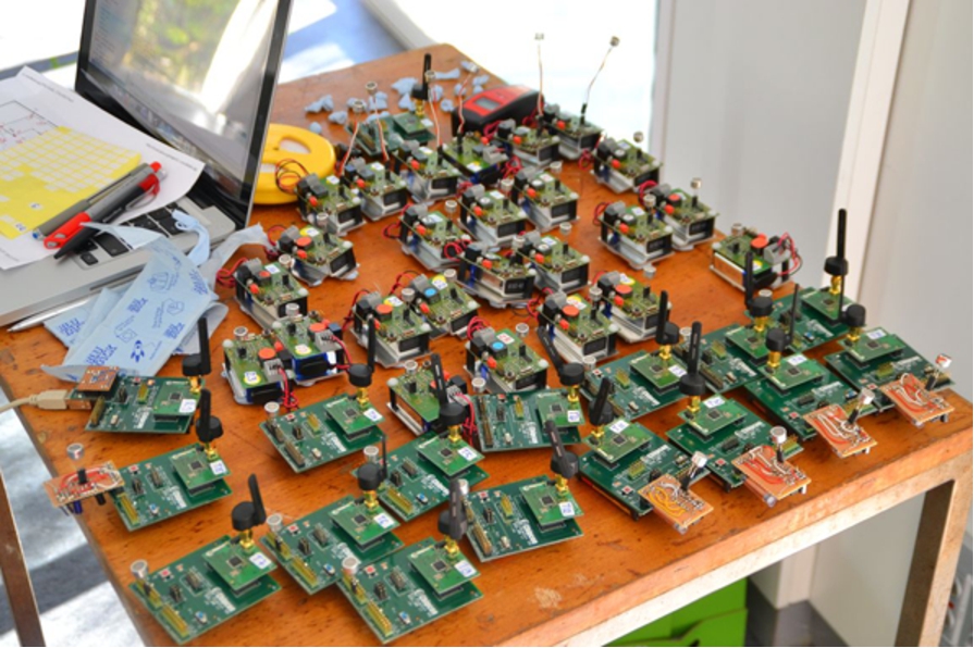
Hardware used for the test run at UP Madrid 2012: Visible are 25 receiver nodes (table left side), 15 calibration nodes (table right side), 5 of them equipped with ultrasound booster amplifiers, and a notebook acting as iLoc server.
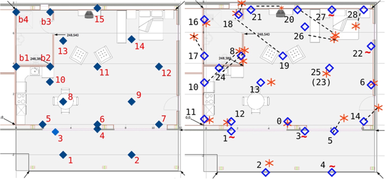
Left: true positions of the calibration transmitters. They have been placed by tape measure. Right: Positions of ultrasound receiver nodes. Diamonds indicate true receiver node positions, asterisk indicate positions determined automatically by the autolocation procedure. Tilde signs indicate receiver positions which were not determined by autolocation. For large displacements between true and calculated position the respective positions are connected with a dashed line.
Then 25 battery powered wireless ultrasound receiver nodes (Fig. 13) where blue-tacked under the ceiling or at the walls at a height of about 2 meters. This manual placement was performed using a sketch indicating desired positions, but the actual positions were not measured, as to save installation time. The actual installation time was about one man hour. The node positions have been documented by photos and have been determined by analysis after the competition.
Then the automatic position determination procedure was triggered. This worked by ultrasound determination of the distance matrix between the calibration nodes and the receiver nodes. Of course a particular node did receive signals only from a fraction of the calibration nodes. The determination procedure did consider the 9 nearest calibration nodes for calculation of the receiver position, or less if there were less reported distances.
Unfortunately, as analyzed only after the test run, the autolocation procedure was only partly successful: In the right part of Fig. 14 the receiver node positions are shown. Diamonds indicate “true” positions which have been roughly determined by evaluation of photos. Asterisks indicate positions obtained by the autolocation procedure. The following 11 node positions could be determined with an estimated error below 1 meter: Nodes 0, 2, 5, 6, 8, 11, 12, 13, 16, 18, and 25. Medium accuracy (1 m .. 2.5 m) has been obtained for the 6 nodes enumerated 14, 17, 21, 24, 26 and 28. The 3 Nodes numbered 10, 19 and 27 were beyond 2.5 m of error. The position of 5 nodes (1, 3, 4, 22 and 27) could not be determined by the autolocation procedure. Therefore these nodes did not contribute to the positioning algorithm, i.e. they were useless. As it can be seen, only a minority of positions has been determined with displacements below one meter. Intentionally it was expected that more or less all or at least the vast majority of the node positions would be determined with reasonable accuracy. During installation, auto-calibration and the test run a variety of sensor data has been logged. Among others this comprises the raw time-of-flight data, the node id’s used for the lateration procedure and the measured distance matrix. From an analysis of this data, the following shortcomings are identified:
The outside area was equipped with four calibration transmitters. This turned out to be not enough: Only 2 out of 5 receivers placed outside have been located and therefore outside position determination was not possible during the test run. The bedroom area was also not well covered by calibration nodes, leading to failure in determination of the nodes 22 and 27. In the region of the two armchairs and the television, position determination was heavily distorted. Data analysis leads to the assumption that the signals of some more distant calibration nodes, namely Nodes 8, 9, 10, and 11 (with respect to the right side of Fig. 14) did not reach the nodes on the direct way but “bounced” one time, e.g. they travelled from the calibration node on the floor to the ceiling, got reflected back to the floor and only then reflected to the detectors at the ceiling. This led to longer TOF values with the effect of “pushing” back the calculated positions from the calibration nodes. Especially sensor 19 with its central role has a large coverage, this influenced the test runs considerably. Also the kitchen area and the bathroom area suffered from displacements between true and detected positions. It is assumed that reflections at the walls in conjunction with long lasting ultrasound pulses (inter-slot interference) introduced the errors.
After auto-calibration, i.e. automatic determination of the 25 receiver node positions, the calibration transmitters had done their duty and were removed from the floor. The iLoc server was switched to normal position detection mode allowing tracking the position of the actor wearing the iLoc badge. As the time for the whole test run was limited, a manual determination of the node positions was not possible, and the tests had to be performed with the autocalibration generated position data. Obviously this limited the accuracy achievable during the test runs.
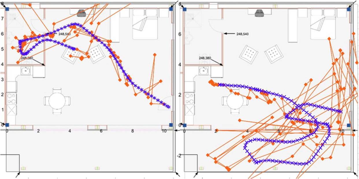
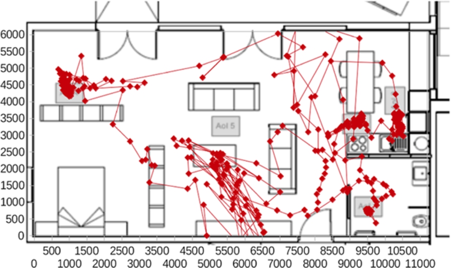
Trace of the actor walking on path 3: Squares indicate true positions, asterisks indicate iLoc+ determined positions. The accuracy was about 2 meters for the 75th percentile i.e. 75% of the iLoc obtained values had an error of less than 2 meters.
However, luckily, the effect of the deviation in node position determination is partly compensated as during the test run the error sources are the same as during the autolocation procedure. The transmitted signal of the node carried by the person to be tracked will undergo the same deviations as the signals from the calibration nodes underwent during calibration phase. In that way, the system works like a fingerprinting system and accuracy is better than expected from the errors in node positions. Also, the multilateration algorithm comprises a “reasoning” mechanism which removes unlikely distance values which can arise for example from wrongly determined node positions. Figure 15 (left) displays a trace of the actor walking on path one from the entry to the bathroom. As it can be seen, the average accuracy is in the range of 1 meter. In Fig. 15 (right) a trace of the third path is shown. Here it can clearly be seen that position determination at the outside area mostly failed. It worked a bit since the glass doors of the lab were opened and the ultrasound signal transmitted by the badge propagated also into the lab where it was detected by receivers 6, 13 and 25. In the entrance area the determination was also quite bad. The table and kitchen area performed reasonable. The two figures show that some areas were quite well covered, while others were not. The iLoc+ system received a score of 3.68 in the accuracy score, which relates to a 75th percentile of about 2 meters, respectively about 40% proper AOI detection. For the meaning of AOI (Area of Interest) scoring, the reader is referred to the competition rules described at [6,7]. This was still on position 3 out of 7 competitors.
Detailed scores of the 2011 EvAAL competition held at CIAMI Living Lab (from [4])
Detailed scores of the 2011 EvAAL competition held at CIAMI Living Lab (from [4])
Detailed scores of the 2012 EvAAL competition localization track held at University Madrid Living Lab (from [6])
Detailed scores of the 2013 EvAAL competition held at Smart House Living Lab (U. P. Madrid) (from [16])
Detailed indoor localization competition scores obtained at the EvAAL 2011- and EvAAL 2012 competition are listed in Tables 2 and 3. For comparison, also the EvAAL 2013 localization track results are given in Table 4. The calculation and weighting of the different contributions to the score did only slightly change between the competitions. So the scores not only within a single competition (i.e. 2011, 2012 and 2013) but also across the three localization competitions are compared.
First, the accuracy column is investigated. At the 2011 competition, iLoc obtained a shiny 7.8 result, which relates to a 75 percentile of about 1 meter. This was beaten only by team A***T which scored about 8.5, but with an availability of only 15% which makes the accuracy result a bit questionable. Besides team A***T, the iLoc score has been the highest, and also not been beaten in the 2012 and 2013 competitions on indoor localization. In the 2012 competition, team C***R came close to the iLoc result by combining IMU and RSSI data. From this observation it can be deducted that ultrasound localization will produce convincing positioning results not seen from pure RSSI based systems. However, the desired degree of accuracy depends on the application. AAL behavioral monitoring, for example, can be performed with relaxed accuracy needs.
While ultrasound seems to be proven leading to good accuracy results, it can not be neglected to discuss also the column “installation complexity”. The complexity rating is based on the systems installation time on site. A total of one hour is allowed for each team to install the system. Slightly simplified, the score is evaluated as 60 divided by the person-minutes per person, finally divided by 6. This leads to a value between 0 .. 10 (negative values are treated as 0, 10 is the best value). So a system which is quickly installed by just placing some sensors without need for position calibration may reach the maximum score of 10. iLoc and iLoc+ both scored 0 in this category.
For the fixed-wired iLoc system this was foreseeable as the mounting of the cabling is a complex task. For iLoc+, the placement of the nodes itself was performed in a reasonable time of about 15 minutes. But the negotiation of the autolocation procedure took much more time than expected, since the position of the autolocation nodes had to be measured on site which took a lot of time. The goal of easing the installation procedure failed.
The majority of systems present at the EvAAL competition indoor localization tracks 2011, 2012, and 2013 performed much better in this discipline. In 2013, for example, all but one competitor installed their system in less than 20 man-minutes.
As a last point in this discussion the “user acceptance” rating is investigated. Also in this discipline iLoc and iLoc+ are at the lower end of scores. The ultrasound transmitter to be carried by the actor needs line-of-sight to the receiver nodes. It has been chosen to use a “name badge” like construction to be worn at the breast. This is somewhat unreliable since the tag can fall down and is difficult to apply. In its current form, it is actually not well suitable for AAL purposes. A second impact on user experience are the receiver nodes themselves. For the EvAAL test installation, the iLoc system needed visible cabling in the room which immediately gave the impression of being in lab rather than in a home situation. While this drawback was overcome by the wireless iLoc+ system in the 2012 competition, the visible nodes, and the amount of nodes employed, are still impacting the user experience.
Scores of the 2011, 2012 and 2013 EvAAL competition localization track grouped by technology. Systems with lack of information or low-scored test run are excluded
The performance of the iLoc(+) systems at the EvAAL competitions 2011 and 2012 indoor localization track has been investigated. Results of the 2013 competition, where iLoc(+) did not compete, have been included. The discussion is introduced by describing the system and the negotiation of the test runs: The iLoc indoor localization systems currently tracks for example 10 mobile nodes with a position update rate of two measurements per second per node, with an accuracy below 10 cm, for single measurements with no temporal averaging applied.
The EvAAL competitions allowed to compare the system with other competitors and technologies under identical conditions close to a real AAL scenario. It is found that
The obtained accuracy results were among the best in the competition. The room affiliations to, for example bathroom, living room, sleeping room etc. was always correct for iLoc, and reasonable for iLoc+. The installation effort was high compared to other competitors. It was still possible to set the system hardware up within 1 hour. User acceptance was low when compared to competing systems Software integration capabilities should be increased.
The installation of the system is possible with moderate effort in typical indoor housing, warehouse or laboratory environments. The development includes the basic ranging electronic setup, firmware, system aspects, the timing- and multilateration algorithms, middleware and application software. Current applications of the system are visitor tracking and fall detection. The two way radio communication enables, among others, applications in the field of ambient assisted living. Long term battery operation is ensured by strict TDMA operation.
The test runs showed that the iLoc(+) system with its considerable amount of nodes to be placed makes it a good choice in special situations where accurate positioning is needed and the wearing of an exposed ultrasound tag is acceptable. The installation effort and the need for the exposed ultrasound tag makes iLoc not the first choice for “main stream” AAL applications like behavioral monitoring in private homes. The latter application is very cost-sensitive and therefore calls for low installation effort and generally needs a high user acceptance.
In Table 5 the results if iLoc and competing teams are grouped by used technology. Of course each competitor has his own special technology and algorithms and the simple grouping can not take this into account. Nevertheless it can be attempted to draw some conclusions from this presentation: Most Wifi systems, including those who add further information i.e. by dead recognition, impose only low installation effort. Zigbee, RFID and Ultrasound mark the other end of the scale and show quite low scores in this discipline. As expected, integrability is not influenced by the used technology. When it comes to accuracy, pure WiFi systems can not convince. The highest score reached is 1.8, which is less than 3 meters. Combining WiFi with IMU technology changes the situation considerably to an accuracy between 1 and 2 meters. ZigBee and RFID based systems are in between the simple- and the complex WiFi systems. The “other” systems generally have a good accuracy comparable to the WiFi/IMU combination. Ultrasound, while being complex in installation and not convincing in user acceptance, is among the best in accuracy.
WiFi and WSN systems use common technologies and provide reasonable results. But systems like ultrasound, which use more complex and less common technologies, typically reach higher accuracies. For iLoc it is proposed to keep high accuracies but reduce installation effort by inclusion of an IMU: A few ultrasound reference nodes are used as anchors for a dead reckoning tracking.
The authors enjoyed having participated at the EvAAL competitions on Indoor Localization. The well defined test runs and scoring procedures allows to compare solutions and draw significant conclusions for further development of indoor positioning systems. The authors are looking forward to the next iteration of measuring the systems.