
Abstract
In this paper, we examine the results of the EvAAL-2013 localization competition. We present a comprehensive description of RealTrac™ technology, the winner of this competition. Focused on real-time location technology, RealTrac hardware includes a server, access points (gateways and repeaters), and mobile devices (voice intercoms and tags). A location calculation engine is based on Bayesian algorithms fusing data from time-of-flight and received signal strength measurements, inertial measurement units, building structure, and optionally, from context events. The peculiarity of the embedded navigation system is that it works effectively independent of the place where the mobile tag is actually attached, i.e., it could be mounted on one’s foot, carried freely in a jacket pocket, held in one’s hand, or even hung on a shoestring. The RealTrac system can easily be combined with third-party systems via the Real Time Location System Communication Protocol that consists of an open API and uses a common Keyhole Markup Language format for geo-data presentation. Furthermore, in this paper, we show that the scores obtained in the competition regarding positioning accuracy might be significantly higher when the applied particle filter is appropriately configured and a probability-based approach for area-of-interest determination is introduced.
Keywords
Introduction
A rise in the application of real-time location (RTL) technology has intrigued the public sector and research agencies, with both exploring new paths of innovative communication. In addition to usage by the general public, social scientists are exploring opportunities for utilizing RTL. By monitoring, collecting, linking, and interpreting RTL data, a new form of social gathering has emerged. One of the major transitions in recent research is the increased requirements for positioning accuracy, motivating a variety of new research programs in and across various competitions.
Social dimension of RTL
Demographic trends of aging populations all over the world have raised the importance of issues involving support and care of the elderly. The duty of new generations is to provide opportunities for such individuals to continue living a safe, rewarding, and interesting life. These opportunities should include, but not be limited to, medical treatment and convenient living conditions. In this new era, a combination of information and communication technologies can help us achieve these goals.
Ambient assisted living (AAL) [1] addresses these goals by exploiting new technologies and exploring ways in which they can be integrated into the everyday lives of senior citizens as well as people in hospitals and nursing homes. AAL provides solutions for creating safe and easy-to-use environments, in particular navigation assistance inside buildings and communication with personnel.
Numerous technologies have been researched and applied to provide location information indoors. Typical positioning systems include the following three components: equipment, techniques, and location estimation algorithms [2]. Equipment can be further classified as infrastructure (e.g., beacons, base stations, anchors, and transceivers) and mobile devices (e.g., receivers and tags). Note that the mobile device is usually attached to one’s body. The entire set of techniques can further be classified by a signal used for position estimation; this includes radio signals (i.e., radio frequency), near field communication and radio frequency identification (RFID), and infrared or ultrasound waves. Some techniques do not require the use of mobile devices, for example, video surveillance or ultrasonic systems, which measure changes in the monitored field of view.
For wireless radio signals, it is possible to measure not only the received signal strength (RSS) but also the time-of-flight (ToF) value and angle of arrival. The location algorithm must fuse measurements from different sensors, apply some constraints, and produce a final estimate of the object’s position. Variations of Kalman or particle filters are usually employed for this task [3].
The EvAAL competition [4] aims at establishing benchmarks and evaluation methods for comparing AAL solutions. The primary goals of the contest are to identify leading suitable technologies, define how these could be implemented within ambient living environments, and suggest how to transfer them into the industry.
Indoor localization competition
In July 2013, teams from France, Portugal, Italy, and the Russian Federation, as well as three teams from Germany, participated in the indoor localization competition held in Madrid, Spain. In addition to our RealTrac team, the description of the systems used by other participants is as follows:
The LOCOSmotion system used WLAN fingerprinting and accelerometer-based dead-reckoning [5].
The AmbiTrack system provided marker-free localization and tracking via a camera-based approach [6].
FEMTO-ST/HMPS presented a system coupling outdoor positioning service with Wi-Fi based fingerprinting and trilateration system, as well as a marker analysis system [7].
The IPNlas indoor localization system was based on fingerprinting in Wi-Fi network using an Android smartphone [8].
The Magsys localization system measured (via a wearable receiver) the strength of the magnetic field formed by stationary transmitters. Next, these measures were transformed into position and orientation information. The underlying principle was the registration of resonant oscillating magnetic fields [9,10].
The AALocation localization system [11] used the ZigBee network and was based on the fusion of data from RSS measurements and presence sensors [12].
Our positioning system, presented by the Russian RealTrac team, earned the first prize in the localization track. Some aspects concerning RealTrac technology were published in [13]. The purpose of our paper is threefold. First, we describe RealTrac technology, particularly concerning AAL systems. Second, we justify the algorithms applied during EvAAL-2013. Third, we discuss possible improvements to our achieved results by tuning the localization algorithms. These settings were determined based on a posteriori analysis of the competition results.
The remainder of the paper is organized as follows. Section 2 contains a description of the EvAAL contest, including competition rules and procedures. In Section 3, we provide a comprehensive overview of RealTrac technology, including network architecture, hardware, protocols, the RealTrac API, voice communication, and other details; note that in this section, we describes the necessary aspects for integrating RealTrac and AAL systems. Section 4 is dedicated to the developed positioning technique, disclosing details regarding the particle filter, the principles of the applied inertial measurement subsystem, and the justification of the algorithm applied for area-of-interest (AoI) determination. In Section 5, we summarize the obtained scores, and in Section 6, we evaluate the results regarding point-to-point localization accuracy and the success of AoI determination. We demonstrate methods for possible improvements in both these aspects. Furthermore, we discuss particle filter performance and dependence on the number of particles. Finally, in Section 7, we present our conclusions and outline our future goals.
EvAAL-2013 competition
Evaluating AAL systems through competitive benchmarking (EvAAL) is an activity focused on evaluating solutions related to AAL by organizing annual competitions. The goal of these competitions is to compare different AAL solutions and provide developers and researchers with an arena in which their technologies can be tested. Evaluation methods and benchmarks are also subject to ongoing refinement and improvement. In addition to comparing algorithms, EvAAL focuses on such solution parameters as cost, deployment difficulty, interoperability, among others.
The third EvAAL competition was organized at the Smart House Living Lab of the Polytechnic University of Madrid, Spain; more specifically, this is where the indoor localization track and AAL tracking was deployed.
The Living Lab building is a single-story building with a control room, a bathroom, and common space comprising a kitchen, a living room, and a bedroom. It also has a porch with a ceiling. In the competition, the localizable space includes the bathroom, common space, and porch.
The floor plan of the Living Lab is presented in Fig. 1, with the height of the ceiling varying from 2.32 to 2.62 m. The Living Lab has some home appliances (e.g., television set, refrigerator, oven, and washing machine). Inside the Living Lab, sensors and actuators are placed for different purposes, for example, flood sensors in the kitchen and bathroom, smoke and fire sensors next to the kitchen, and magnetic contact sensors on some doors and windows. A domotic bus provides notifications for all events, with each event recorded with its specific coordinates. This information is available for use by a localization system.
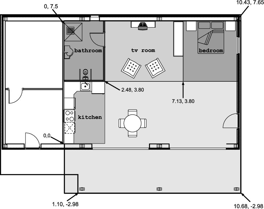
Smart House Living Lab plan.
Although localization systems have actively been investigated and used for a long time, there is no common standard as to how to develop them, and which services and components they should have. Therefore, the competition’s organizing committee proposed a set of criteria to comprehensively rate systems not only with respect to accuracy but also convenience for daily use, ease of integration into house interior, installation complexity, and reliability.
These five criteria were weighted according to their importance as follows:
Accuracy (weight 0.35),
Availability (0.20),
Installation complexity (0.10),
User acceptance (0.20), and
Interoperability with AAL systems (0.15).
Total scores were calculated by weighting all five criteria with the corresponding weight factors.
The accuracy of each system was evaluated by averaging the scores across the three phases described below.
In the first phase, the positioning system should determine the AoI in which the object is. The typical AoI included the bathroom, the front of the kitchen, and the area near the dining room table.
In the second phase, the positioning system should estimate the real-time position of a single user in the scene without any disturbances.
In the third phase, the system should evaluate the user’s position in the presence of another person who moves freely inside the localization area.
The AoI accuracy score was given by the expression
T is the fraction of time in which the localization system provides the correct information regarding user presence in a given AoI and user absence from any AoI;
U is the fraction of time during which the system confuses a small area with a big area that contains a small area (big areas are presented in Fig. 1; small areas are not shown).
To calculate the point-to-point accuracy score, the individual error of each measurement was evaluated as the Euclidean distance between the measured and expected points. Next, the 75th percentile P of the errors was determined and scaled according to the formula below.
The organizers allowed the competitors to install their equipment within 1 h. The time spent preparing was incorporated into installation complexity criteria (see rules in [14]).
By the end of the installation stage, trajectory recording began. If the technology assumed the use of mobile tags, then such tags were given to the actor in advance. In some cases, the actor was instructed to wear the tag in a specific manner. For our RealTrac system, the actor was free to place the tag anywhere on the body since the technology does not have any restrictions regarding tag placement on a user’s body – it can be in one’s pocket, in one’s hand, or even hanging on a shoestring as a necklace. Next, the actor moved along a few predefined paths with stops at predefined points, as shown in Fig. 2. The true ground trajectory was not disclosed to competitors.
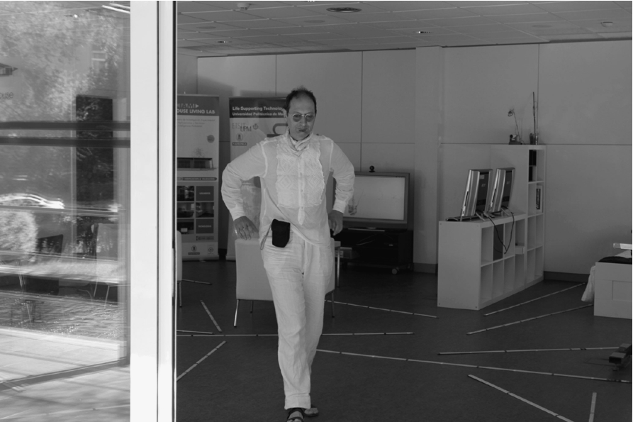
An actor moves along a predefined trajectory; our mobile tag was placed freely in the left front trouser pocket.
The phases indicated above were performed twice, and the best marks were recorded. After completing this portion, the last two evaluation criteria (i.e., user acceptance and interoperability with AAL systems) were evaluated using questionnaires. Many questions regarding every aspect of the developed system were asked – from device size and charging requirements to the ability to utilize the system in the Open Source community.
Previous research showed that typical errors of ToF ranging for nanoLOC hardware indoors were usually comparable with the size of the room [15]. Therefore, given an area of 121 m2, only four access points were used as anchors in the Living Lab. The anchors were installed near the corners of the room to cover the entire localization area. Two access points were placed at metal beams near the ceiling of the porch area (
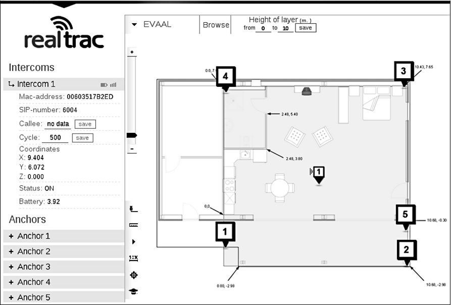
RealTrac graphical web interface with numeric marks indicating the placement of access points in the Living Lab.
Since all access points were powered from external batteries, the installation process was very quick – the installer spent only 2 min and 1 s on system deployment.
RealTrac localization algorithms used the following three data sources: ToF data, RSS data, and trajectory data recorded by an embedded inertial measurement unit (IMU). Localization accuracy depends on the quality of these three data sources. Among these three sources, the IMU data contributed to the accuracy to the greatest extent.
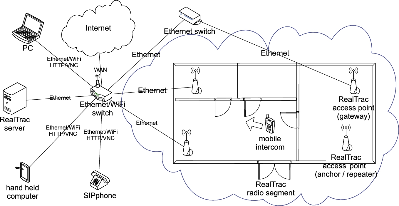
RealTrac technology network diagram.
Given this, we decided to hide all access points in the ceiling. On the one hand, this decision led to less-accurate ToF ranging; on the other hand, it resulted in better user acceptance criteria scores.
The use of additional anchors inside the room was not reasonable. It did not lead to any increase in location accuracy because the NLOS errors were high and an additional ToF radius did not yield a substantial reduction in the localization area.
Note that the organizers provided access to all location-based events that occurred in the system in the Living Lab. For example, manually switching the lights on or off generated the corresponding event. In this case, the localization server could position the person who pressed the button near the switch. Unfortunately, in our 2013 RealTrac system, we did not implement the ability to use third party geo-events in the localization algorithms.
Detailed results of the RealTrac system are presented in Section 5. Final scores and the jury decision scores of all competitors are summarized in Table 2.
RealTrac technology has been developed by RTL-Service JSC (Petrozavodsk State University, Russian Federation) since 2008. Applicable to the localization of mobile devices and voice communication between intercoms, such technology is based on the nanoLOC radio standard (IEEE 802.15.4a CSS) developed by Nanotron Technologies GmbH. The main features of this standard include a high data rate of 1 Mbit/s, an automatic ToF round trip time ranging procedure, and low power consumption.
Network operation scheme
As shown in Fig. 4, the RealTrac system comprises mobile devices (intercoms and tags), access points, and a server.
Access points form a radio segment. They can measure distances to mobile devices using the ToF method and send these data to the server. Access points are connected to the server via Ethernet; therefore, a RealTrac system can be installed in a building with an existing wired network.
The server estimates mobile device location after receiving the measured distances from the access points. Locations can be displayed on a browser on any laptop connected to the Internet. Furthermore, a third-party application obtaining location data from the server can be developed, for example, through HTTP.
Radio segment coverage can be enlarged using access points operating in a repeater mode.
Depending on the application, the RealTrac system can support any number of mobile devices.
The effective time of one frame transmission, including interframe space, headers, and an acknowledgement, is ≈1.4 ms. In the round trip time (RTT) scheme, each ToF measurement consists of three successive Data/Ack frame exchanges. Therefore, the total time required for one RTT ranging is ≈5 ms.
To determine the tag inside the localization area, at least three ToF measurements from the access points are required. In practice, four or five such measurements are recommended. Thus, the system is not permitted to perform more than 20–25 measurements/s, as the 2.4 GHz ISM bandwidth is limited.
Based on the above, the maximum number of mobile devices in one network segment depends on the distance measurement frequency. For example, if the position update period is 1 s, then the network can process no more than 20 mobile tags. If the position update period is 10 s, the number of tags can be increased to 20, and so on.
For technical details on the RealTrac radio system and operation algorithms, see [13]. Additionally, the subsections below describe the main characteristics of the hardware devices and software components of the system.
RealTrac hardware units
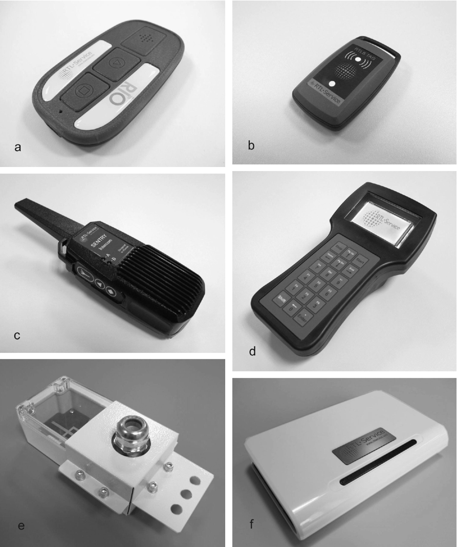
RealTrac technology hardware: (a) duplex intercom Rio®; (b) tag – mobile sensor; (c) half-duplex intercom radio Sentry®; (d) wireless handheld network analyzer; (e) industrial outdoor access point; and (f) indoor access point.
The RealTrac system consists of different types of hardware units. All the hardware devices are roughly divided into four groups, as mentioned below.
Access points – data transfer devices providing radio network infrastructure (Figs 5e–5f).
An accessory device for primary network setup and testing performance (Fig. 5d).
A Server – a node that collects and analyzes data and manages the sensor network.
Mobile devices (intercoms and tags) are equipped with the following:
pressure sensor,
temperature sensor,
RSS meter,
three-axis accelerometer,
three-axis gyroscope,
three-axis magnetometer, and
RFID tag.
An intercom operates in a cyclic manner at a certain frequency – i.e., it wakes up, listens to its radio segment for incoming packets, performs certain operations (if requested by the server), then sleeps during the rest of its cycle time. Thus, it provides the required frequency of distance measurements while conserving battery power. The duration of this cycle can be adjusted by server-side software.
When an intercom accepts an incoming call or initiates a call itself, it is put into the sound mode and does not sleep at all. After the call is finished, the intercom switches back to the power-saving mode. A tag operates according to the same scheme.
Access points
Stationary RealTrac nodes (i.e., access points) are equipped with the following:
pressure sensor,
temperature sensor, and
RSS meter.
The two key features of the access point are distance measurement and data transfer from the radio segment to the server.
The access point operates in one of two modes, either gateway or repeater mode. In the gateway mode, the access point receives data from mobile nodes including ranging results, system data, voice streams, and sensor data. It then transfers these data to the server.
The repeater mode implies that the access point repeats all received packets from the wireless network and increments the hops field in doing so. Evidently, it skips packets sent from itself and only retransmits packets that it has never repeated before.
Access points participate in a distance ranging procedure in both modes.
The mode is automatically selected when the device starts up. If the access point is connected to Ethernet when the power is turned on, it operates in the gateway mode; otherwise, it operates in the repeater mode. In the gateway mode, the access point sends a broadcast DHCP request to obtain an IP address from a local DHCP server.
An access point communicates with the RealTrac server through the Inter Nano Communication Protocol (INCP) [13].
If a local network contains a specifically preconfigured DHCP server, then this server returns the IP address of the INCPd server that the access point should work with. Next, the access point communicates with the INCPd server directly using INCP.
Otherwise (i.e., if a local network contains only a common DHCP server), the access point obtains the default network settings and sends a special DNS request to which a DNS server returns the IP address of the INCPd server that serves the given access point.
In the repeater mode, the access points do not have IP addresses and hence wireless INCP communication goes over the nanoLOC data link level.
The effective bandwidth of gateways and repeaters is limited by the radio throughput and does not exceed 500 Kbps.
The total occupied bandwidth of the network depends on the number of installed repeaters. Use of repeaters decreases the performance because of frame duplication, unnecessary retransmissions, and unavoidable collisions.
Note that there is only one case in which using a large number of repeaters is possible, namely, in mines, where long chain-like segments would be organized.
Analyzer
The analyzer is an essential device for system maintenance and deployment assistance. It can be used for experiments, radio monitoring, and other tasks. Apart from other RealTrac hardware, the analyzer is equipped with a keyboard and graphical display for enhanced user interaction.
Features provided by an analyzer include the following:
searching and identifying nearby active devices;
displaying information regarding devices, filtered on-demand;
displaying information regarding network status, such as RSS and number of neighbors; and
configuring analyzer settings.
The analyzer is equipped with an 1800 mAh battery, which guarantees that the device can work continuously for up to 14 h without recharging.
Server
For the EvAAL-2013 competition, we used a Dell Inspiron Ultrabook with 4 GB RAM and an Intel® Core™ i5-3317U (1.7 GHz) processor as our server.
Software architecture
As illustrated in Fig. 6, the modular software structure of the RealTrac technology comprises the following components:
RealTrac server (localization module, INCPd server, and RTLSCP server);
Asterisk voice communication server;
Optional application server (see “RealTrac application server” and “Third party application server” in Fig. 6); and
Client software (see “RealTrac web client” and “Third party web client” in Fig. 6).
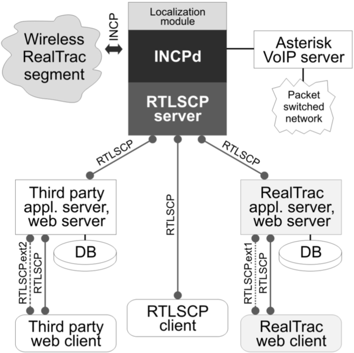
Modular software structure of the RealTrac technology.
The INCPd server is responsible for the intercommunication between the hardware and software components. This server manages the wireless network, integrates the access points into the system via Ethernet, and mediates between hardware devices and other software components. As a result, software components can communicate with hardware devices as with other software entities. The INCPd server and access points use INCP to provide data and sound transfer to and from them. A brief description of INCP is presented in [13].
One of the key components of the INCPd server is a localization module that calculates the location of a given device using all available information. The localization module uses its own database for storing temporary data required for further location estimation.
The INCPd server handles the following data regarding devices:
global coordinates,
movement trajectory obtained from an embedded IMU,
number of human steps obtained from IMU,
device battery voltage,
position update cycle frequency,
measured absolute pressure,
measured temperature, and
measured RSS value of an incoming radio frame.
The RealTrac server provides an API by implementing the Real Time Location System Communication Protocol (RTLSCP) (see “RTLSCP server” in Fig. 6). This public API is a part of the RealTrac API. On the basis of the representational state transfer (REST) architectural style, RTLSCP uses JSON notation for requests and responses, and was designed to simplify third-party application development (see “Third-party application server” component connected to “RTLSCP server” in Fig. 6).
The basic RTLSCP version provides only a few features, including device list and location requests and device configuration options. Location information is provided in global coordinates (i.e., latitude, longitude, and altitude) that works well with common geo-services such as Google Maps. RTLSCP is described in more detail in Section 3.5.
In addition to the basic RTLSCP version, the extended version of the protocol consists of optional features such as location history, event notifications, and voice calls history. The RealTrac system incorporates the extended RTLSCP version as a separate component (see “RealTrac application server” in Fig. 6 and note the second connection with “RealTrac web client” marked as “RTLSCP.ext1” that reflects the extended RTLSCP version).
Technically, the application server is an RTLSCP client of the RealTrac server. It might obtain, for instance, location data from the server and store such data in a separate database to provide location history on demand. Data caching might be implemented on the client side, but a better place to realize such business logic is on a server.
The application server provides the following information through the extended RTLSCP:
location history,
maps images storage,
mobile device owner details,
distance from a given point to a device and its direction,
event notifications related to entrance to and exit from a given area, as well as two devices meeting,
event notifications related to RFID-based access control,
object’s motion details (e.g., static, walking, running, and cycling), and
alert notifications (e.g., fall of the owner and alert button click).
The INCPd and application server are both developed using JDK 7 and various open source libraries.
A third-party developer can extend the application server to provide additional data to a client via new JavaScript modules; however, the provided RealTrac application server and its web client implement most common features and are ready to use as is. The web client application is a good example of how to integrate the RealTrac system into a corporate application (or an AAL system).
Voice communication is provided by the open source PBX Asterisk software (see “Asterisk VoIP server” in Fig. 6). The RealTrac system supports duplex and half-duplex voice communication between intercoms and between an intercom and a static SIP-phone connected to the server. The system can be extended to support voice communication between RealTrac hardware and traditional telephones or cellular phones by installing a special telephony adapter on the server.
When intercoms are moving within the wireless network coverage, automatic roaming is supported by the system server. In such cases, sound packets are sent through the nearest access point to the given intercom.
Voice communication is the most resource-intensive feature of the entire system. Accordingly, there are quite evident requirements for the server hardware.
The RealTrac voice communication feature is described in more detail in [13].
RealTrac API
As localization in AAL scenarios can be exploited by other applications to offer advanced services, integrability becomes a very significant parameter for localization systems.
Modern software and hardware systems are often complex and continuously evolve during the maintenance phase. The architecture of such systems must be robust to changes to enable support and keep the development process easy and effective. Furthermore, the ability to extend such systems is even more important.
A stable system architecture has well-defined interfaces between core components of the system and public APIs for third-party extensions and use. Special attention should be paid to public system APIs because their usability causes the success (or failure) of the system among developers, and consequently, in the market.
Common principles of effective system APIs include the following:
Simplicity. The API must be easy to learn and use. Ideally, the API does not require extra documentation to learn; a few descriptive paragraphs should be sufficient to start.
Implementation independence. Implementation independence allows developers, for example, to change the programming language used for the implementation of the API without changing the API itself. This also means that third-party developers can use any language or technology to create clients of the API.
Robust to change. A good API must be robust to changes in the underlying technology. For example, new hardware might be substituted for old, and the API of the system based on the old hardware should not require changes.
Extensibility. API extensibility allows core developers to add new features to the system without negatively impacting published API versions.
The RealTrac system is equipped with REST-based HTTP services that comply with all of the above principles. These HTTP services form the RTLSCP – the public API for the RealTrac system. Formats of requests and responses of these REST-based services use JSON notation. The principles of a good API listed above are implemented as follows:
Simplicity is provided via the JSON notation itself. JSON is easy for individuals to read and write. Moreover, RTLSCP uses well-known terminology such as anchor, beacon, and node in request specifications. Hence, no special documentation is required for understanding the protocol.
To achieve implementation independence, the current RTLSCP implementation is based on the Java Virtual Machine; however, it could be changed without affecting RTLSCP, because JSON is completely language independent and does not limit core and third-party developers as CORB or other RPC technologies and notations do.
For robustness, if the hardware of the RealTrac technology changes, then RTLSCP is still applicable because hardware does not touch the items of RTLS.
Extensibility is provided by the REST specification since any number of new services could be created by simply adding new URLs and corresponding request specifications to the list of available RTLSCP services.
RTLSCP covers most common features of any RTLS and provides services for handling RealTrac hardware and visualization. The common API provides the following data:
Real-time locations of anchors and mobile nodes,
Lists of anchors and mobile nodes, and
Location calculation results in absolute and relative coordinates.
The following additional data structures are served by the RealTrac APIs:
Anchors and mobile nodes parameters and statuses, and
Keyhole Markup Language (KML) files for visualization.
An example of a typical RTLSCP request and corresponding response are presented in Listing 1 and Listing 2, respectively. The request contains one parameter, a list of MAC addresses whose locations are requested.
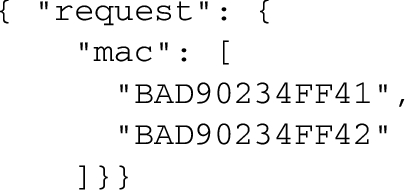
RTLSCP request example 1.
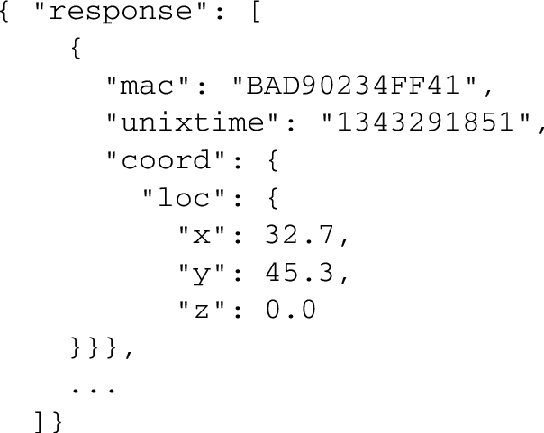
RTLSCP response example 1.
The response consists of the list of structures that in turn consist of the MAC address, the location calculation time, and the coordinates of the object. In this example, the
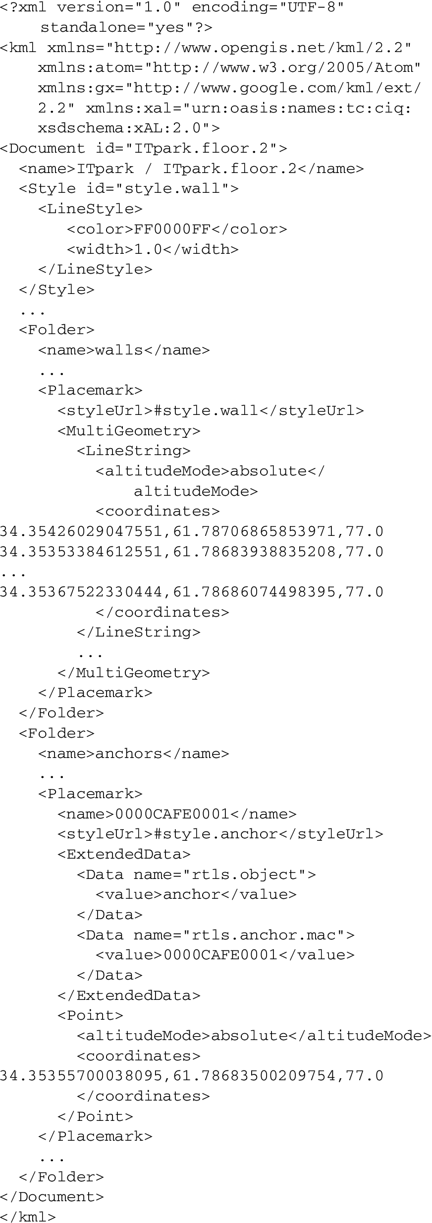
One of the main RTLS options is to visualize the calculated location in relation to specified physical objects. The easiest way to present a location in a web browser is via Google Maps. Given the growth in the popularity of web interfaces in recent years due to their simplicity of implementation and support, as well as cross-platform features [16], KML-formatted files were proposed for use in RTLSCP. KML is natively supported by both Google Maps and Google Earth applications. A distinct REST service in RTLSCP allows all data for visualization to be acquired as one KML file; more specifically, this includes anchors and mobile node locations and statuses.
Listing 3 gives an example of such a KML file; it consists of coordinates and metadata for walls and anchors, and defines the color of wall lines. First, the building name (“ITpark/ITpark.floor.2”) and wall line color (“FF0000FF” in <alpha><RGB> format) are defined. Second, wall coordinates are presented, and finally, the list of anchors and its properties are defined.
RTLSCP response example 2.
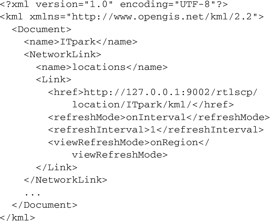
The REST service allows one to request actual object locations as another KML file, which provides only new location coordinates that can be used to update existing positions on the map. Using a similar approach, it can also provide updated anchors positions.
As an example, to incorporate this KML file into a Google Earth application, it is first necessary to use a special KML file that describes a resource to obtain actual locations (see Listing 4). The structure and format of the file with new locations is almost identical to the main KML file; therefore, it is not presented here.
RTLSCP response example 3.
Third-party developers can easily integrate these two KML files into standard Google Earth applications while testing the RealTrac system during deployment.
All location coordinates are received in one of the following two formats:
absolute (latitude, longitude, altitude);
relative (x, y, height).
By default, KML files contain locations in absolute coordinates. Two location coordinate formats allow third-party developers to begin with a simple relative coordinate format that can be quickly integrated into lightweight RealTrac client applications. Rich web and desktop applications that use Google Maps plugins or other plan visualization utilities that require latitude, longitude, and sometimes altitude can benefit from the absolute coordinates format.
In summary, RTLSCP provides a simple and robust public API that can be used to implement additional business logic, thus providing the possibility of integrating RealTrac technology into existing corporate and open source systems.
Integration with AAL software was one of the key parameters in the overall scoring criteria at the EvAAL-2013competition. The RealTrac system mainly conforms with the integrability criteria defined by the organizers, since the technology provides an API to RTLSCP, as described in Section 3.5.
To integrate the RealTrac software system with the EvAAL benchmarking software, the so-called “light” integration procedure was used [17]. This procedure consisted of sending simple text messages to the benchmarking software over TCP. The developed middleware requested device coordinates from the RealTrac server software using RTLSCP commands, and then sent localization data to the EvAAL benchmarking software with a 2 Hz update frequency. The same middleware generated AoI events.
The text message with localization data contained the following fields:
competitor identifier (a string); estimated X coordinate of the object, represented in decimal form; estimated Y coordinate of the object; integer representing the POSIX timestamp of the current location estimation; and list of numbers representing the AoIs in which the object is located.
Positioning technique overview
The RealTrac technology is based on nanoLOC (IEEE 802.15.4a) transceivers operating in a 2.4 GHz bandwidth. This radio standard utilizes the chirp spread spectrum technique and provides automatic ToF RTT ranging.
Ultra-wideband (UWB) technologies (also defined within the IEEE 802.15.4a standard) are the main competitors to nanoLOC in terms of ToF measurements. UWB has a substantial advantage in that it provides more accurate distance measurements since the spectrum is considerably wider; however, the range of reliable communication is less. Regulations on radio transmission power set an upper limit of
The communication range is tightly connected to the spatial density of the deployed equipment and influences the overall costs of the local positioning system. This enables nanoLOC-based hardware to technically compete in some market niches, particularly in applications that require location accuracy of 1–3 m.
As mentioned above, the most accurate and least costly positioning might be achieved by an inertial navigation system. With this approach, the trajectory is obtained by an IMU embedded in a majority of off-the-shelf handheld devices. In addition to this trajectory being relative to some origin, the use of these data is a powerful technique for increasing localization accuracy. The data from IMU can be used separately to determine the indoor location [18,19] or fused with information from wireless sensor networks for better location accuracy.
Numerous systems utilize IMU data together with RSS data. Such systems are based on RFID [20] technologies or WiFi [21,22]. The latter is widely used because of the ease of implementation on smartphone platforms. Another group of systems uses IMU together with the UWB technique [23–25]. Though there are several systems processing IMU data together with RSS or UWB measurements, there is currently a lack of systems that use IMU together with ToF RTT nanoLOC data.
The use of IMU as an additional source of information for nanoLOC-based systems allows such systems to compete with UWB-based systems in terms of installation complexity and system costs, as well as with RSS-based systems in terms of localization accuracy.
The choice of which positioning algorithm should be used depends on the information available. A majority of IMU-plus-RSS-based systems use particle filters for data fusion. The IMU-plus-UWB-based systems use the extended Kalman filter for processing more accurate UWB measurements.
Furthermore, the Kalman filter can be used for fusing ToF RTT-based measurements in the 2.4 GHz range with IMU data [26]. However, this approach requires accurate IMU data that can be measured by a wheel-based robot and absence of NLOS errors that can be achieved only outdoors. The positioning system focused on indoor pedestrian localization implies less accurate IMU data. The presence of severe NLOS errors in ToF measurements indoors makes the application of the Kalman filter considerably more difficult.
The RealTrac technology enables measurements of both distance and path loss between an access point and a mobile node. The IMU data are used to improve positioning accuracy. The localization server is configured to use KML-formatted information about the locations of access points and building structure (i.e., walls, stairs, rooms, corridors, and furniture). As depicted in Fig. 6, location calculation starts as the INCPd server resends the following data to the localization module: MAC addresses of access points, MAC address of a mobile device, corresponding set of distance and path loss measurements, and information from the embedded IMU.
Further details concerning IMU algorithms are discussed in Section 4.1.
Several positioning algorithms that fuse this information have previously been studied [15,27]. For the EvAAL competition, the particle filter was chosen to calculate the position of the object (see the description in Section 4.2). This novel approach for the fusion of IMU data with ToF data allows us to construct the particle filter without using the weights.
IMU-based localization
Positioning accuracy might be significantly improved if the three-axis accelerometer and gyroscope are used. The developed IMU-based navigation engine does not restrict the typical usage scenarios of a RealTrac device and assumes it could be placed wherever the person finds it suitable.
To increase the battery lifetime, the power-saving mode of operation was implemented. While the accelerometer is always in an active state, the gyroscope is turned on only when motion or a walking pattern is detected. The gyroscope calibration settings are calculated during normal operation and stored in non-volatile memory.
The IMU-based engine includes distance, orientation, and trajectory calculation modules, described in detail in [28].
The first module estimates the total distance travelled by counting the number of steps and calculating step lengths. The step counter detects a step with an accuracy that exceeds 98%. The proposed step counting technique showed advanced performance without regard to orientation of the device, walking speed, or physical characteristics of the person. For step length
Quaternions were used to represent the altitude of the device. Because of the limited computational resources of the microcontroller unit (MCU), the complementary filter in time discrete form was applied [29]. A person’s heading was extracted from quaternion observations as the mean of two two-dimensional vectors corresponding to the last two steps.
The position update was performed on the step basis. As the system detects a step, it acquires a step length and a step heading direction. Both are passed to the trajectory calculation module in which a new position point is added to the trajectory. All processing is performed by the internal MCU of a mobile device. As the time to send the data to the server approaches, new calculated trajectory points along with ToF and path loss data are included in the INCP message.
IMU performance was evaluated through experiments. The Return Position Error parameter, i.e., the computed return position in comparison with the real one, for multiple tests did not exceed 6% of the total travelled distance [28].
The IMU trajectory can provide position estimation even if ToF measurements are unavailable, and can be used as an extra constraint in particle or Kalman filtering techniques.
To fuse all information available in the localization server, the particle filter was used. The particle filter is a very efficient algorithm that is widely used for location calculation with noisy measurements [30]. To represent the uncertainty of an object position, a set of random samples or particles with corresponding weights is used. Each particle represents the possible state of the mobile object, considering information regarding object position and direction. Particles move according to the selected motion model and are subject to constructional restrictions; for example, they cannot pass through walls. After several steps of the algorithm, the particle set converges to the factual state of a mobile object.
In the current implementation, at each time moment t, the system state is characterized by the set of particles
For simplicity, the ToF measurements are used only for geometrically removing particles from the location area. Therefore, no weights are used. The typical phases of the particle filter algorithm, including initialization, propagation, update, resampling, and state estimation, are described below.
Initialization
During the initialization phase, the set of N particles is randomly generated within the area of the intersection of circles corresponding to the ToF measured distances, as illustrated in Fig. 7. The motion directions of the particles are uniformly distributed in the range from 0 to 360 degrees.
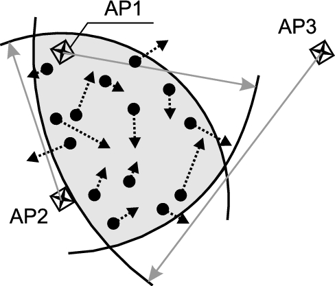
Initial particles, generated inside the circle intersection area; AP1, AP2, and AP3 are access points, forming the circle intersection area; the radii of the circles are equal to the ToF measured distances; solid dots denote particles; and the arrows indicate particle positions after the propagation phase.
In the propagation phase, the next position of a particle is determined by the trajectory obtained from the IMU. The trajectory between two sequential moments of ToF measurements
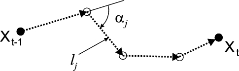
Example trajectory acquired from an embedded IMU; black circles show the moments of ToF measurements,
The particle coordinates and direction are changed according to the following motion model equation:
Structural information regarding the building is used to increase positioning accuracy [31]. If a particle crosses a wall during its motion, the particle is removed from the current set (see Fig. 9).
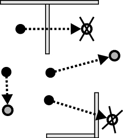
Particle propagation restricted because of building structure.
After the propagation step, only K out of N particles survive. It is possible that the final particle set is empty (i.e.,
The update procedure is applied when new ToF measurements are received. First, the location area is formed by intersecting the circles corresponding to the ranging results. Second, the propagated particles that occurred outside the intersection are removed from the final set. Thus, after removal, only M particles survive.
Resampling
Since there is no weight calculation used in the described algorithm, a resampling procedure differs from the typical procedure [30]. Each particle from the set of M surviving particles is duplicated n times, where n is the closest integer to
State estimation
As a final step, the object location is calculated as the average of the particles as follows:
The particle filter algorithm is presented below using pseudo-code.
The following input data is used at each iteration of the algorithm:
Draw the area of circle intersection corresponding to the received measurements If Calculate new particle positions From set From set Resample the rest of the particles Calculate object location by averaging the resampled particles from set
AoI determination
There are two ways to determine the area within which an object is located. The straightforward approach is to determine whether the location point is inside a certain AoI. We used this approach in the EvAAL-2013 competition.
A more robust approach uses a particle state representation, i.e., based on the probability of an object being in a certain area. This could be estimated as the number of particles inside the area divided by the total number of particles. An event stating that the object is inside the area is generated when the corresponding probability exceeds a certain threshold, for example 50%.
A true-to-life situation happened at the EvAAL-2013 competition and depicted in Fig. 10 demonstrates these two approaches.
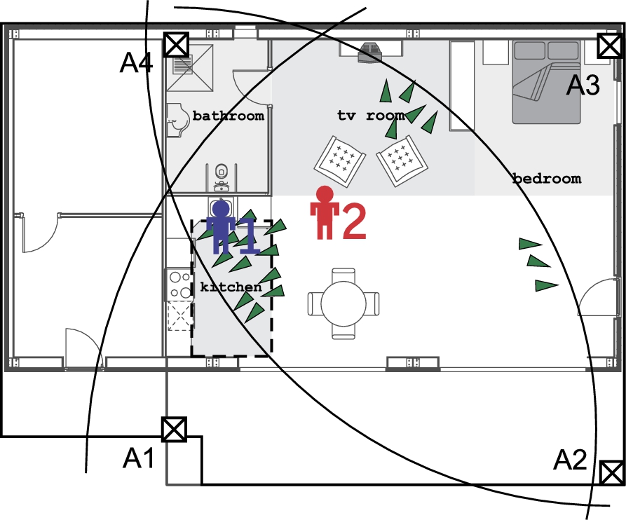
Area-of-Interest determination by a particle cloud; A1, …, A4 are access points with circles corresponding to the ToF measurements; kitchen, bathroom, tv room, and bedroom are AoIs; 1 indicates the true position of the pedestrian; 2 indicates the averaged (by all particles) position of the pedestrian (incorrect proposition); green triangles indicate particles corresponding to the possible locations of the pedestrian.
In the figure, the true position of the pedestrian is labeled 1. Furthermore, the particle cloud is separated into three groups. One group is located near the true position of the pedestrian in the kitchen area. The two other groups are in the tv room and the right bottom corner of the hall near the door. Straightforward calculations according to (6) yield the object’s position marked by label 2. Thus, the object belongs neither to the kitchen area nor the tv room, and the corresponding event of being in the certain AoI did not occur.
Since a majority of particles are concentrated in the kitchen area, however, their relative number exceeds the threshold for AoI determination. The AoI event might be generated in this case, a scenario corresponding to the ground truth.
Note that in Section 6, the term “the improved AoI determination algorithm” is used to refer to this probability-based approach.
The organizers used two approaches to test the performance of the competing positioning systems. First, they determined point-to-point accuracy for predefined traces. Second, contestants provided real-time data upon entering certain AoIs. To compare the results of the locations, a calculation of the 75% quantile of the positioning error cumulative distribution function (CDF) was used.
There were four different traces with different lengths and shapes. The ground and calculated traces with the corresponding CDF obtained during the EvAAL-2013 competition for the RealTrac positioning system are shown in Fig. 11.
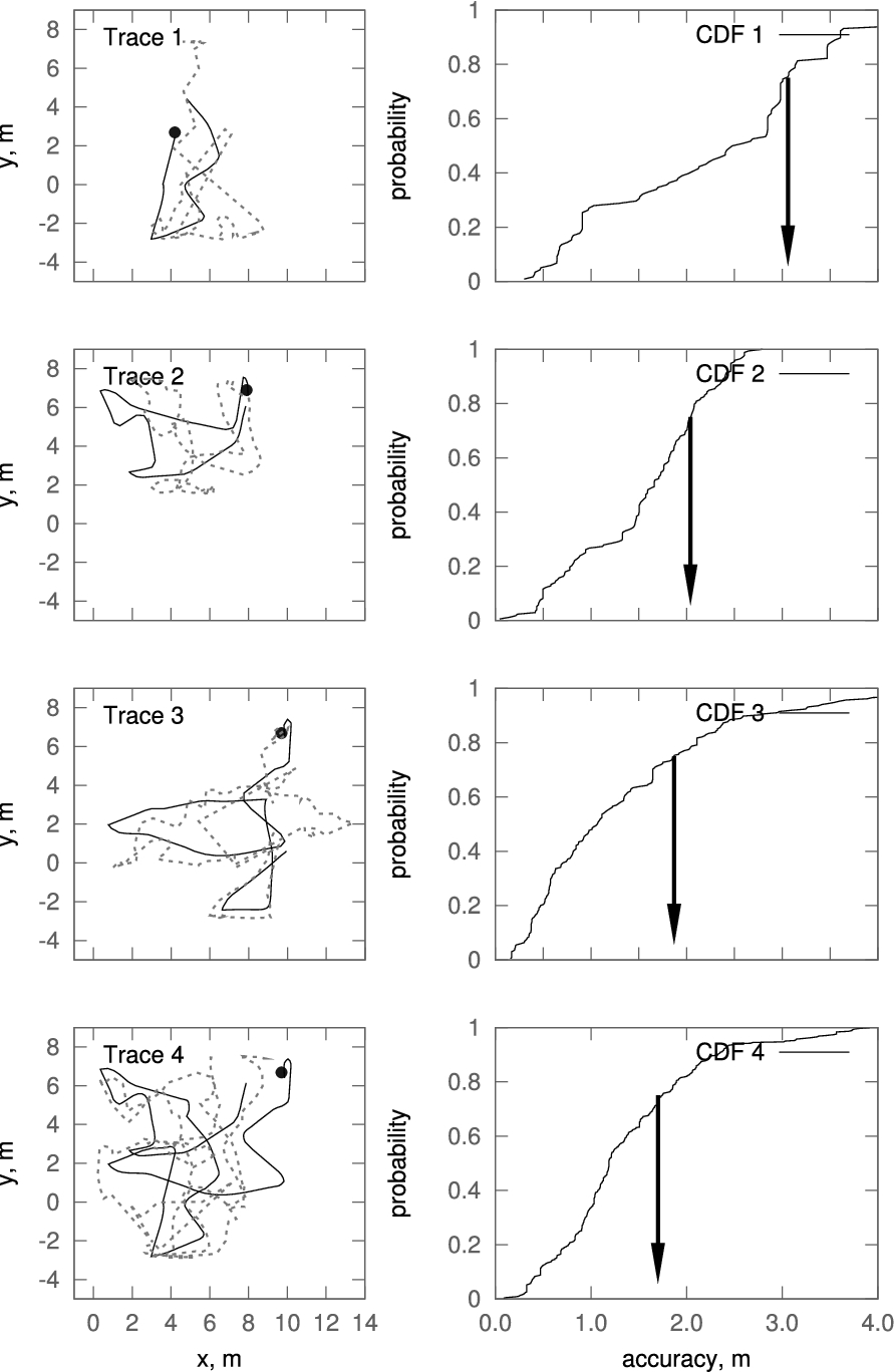
Four traces and corresponding CDFs during the EvAAL-2013 competition; black solid dots indicate the starting points of the traces; the OX and OY axes of the left plots correspond to coordinates of the building; the OX axis of the right plots corresponds to the point-to-point accuracy, whereas the OY axis corresponds to the probability of locating a person with the given accuracy; solid lines on the left plots correspond to ground traces; dashed lines correspond to calculated traces; arrows in the right plots indicate 75% quantile accuracy.
In the figure, the solid lines in the left plots correspond to the ground traces, whereas the dashed lines correspond to the traces calculated by the RealTrac system during the EvAAL competition. The OX and OY axes of the left plots correspond to OX and OY coordinates of the building. The CDFs for the corresponding traces are shown in the right plots, with the OX axis corresponding to the point-to-point accuracy (i.e., positioning error) and the OY axis corresponding to the probability of having a certain positioning error. The black arrow indicates the error for the 75% quantile for the given CDF.
RealTrac accuracy and availability results. B1.1 – one person, first path (the shortest one), B1.2 – one person, second path, B2.1 – two people moving around, B2.2 – AoI test
EvAAL-2013 overall scores
For the first (shortest) trace, the 75% quantile of point-to-point accuracy was equal to ≈3 m, for the second trace, it was ≈2 m, for the third trace, it was ≈1.9 m, and for the fourth (longest) trace, it was <1.7 m. The efficiency of the particle filter depended on the convergence speed of the algorithm. The longer the trace, the better the accuracy results achieved. For the shortest trace (trace 1 in Fig. 11), the algorithm did not have sufficient time to converge, thus leading to poor accuracy results (≈3 m @75%).
Detailed results obtained by the RealTrac team in comparison with other competitors are presented in the next two tables.
Table 1 describes accuracy and availability results during the four walking sessions.
Rows B1.1, B1.2, B2.1, and B2.2 correspond to traces 1, 2, 3, and 4 in Fig. 11, respectively. The first two columns show the 75th percentile of the distance between true and estimated positions. The last four columns reveal the scores obtained by the RealTrac system for accuracy and availability during the first and second attempts. In benchmarks B1.1 and B1.2, only one person walked around the Living Lab with brief pauses following the predefined paths. In benchmark B2.1, one person moved along the predefined path; at the same time, an additional actor moved freely inside the Living Lab space. In benchmark B2.2, the actor walked along the coupled traces from B1.2 and B2.1. For benchmarks B1.1, B1.2, and B2.1, the point-to-point accuracy was selected as the accuracy score; for trace B2.1, the AoI accuracy was measured.
These results show that the RealTrac system converges to the true position of the actor in time. Some loss in the availability score (see columns for the availability criterion for the two attempts in Table 1) can be explained by the fact that the system provided exactly one sample every half second, and sometimes packets were lost or delayed.
Table 2 describes the obtained scores for all participating teams, showing results for each contest criterion, namely, accuracy, availability, installation complexity, user acceptance, and integrability within AAL. The first three scores were calculated by benchmarking and the last two were calculated by a questionnaire. The total score, obtained by weighting, is also presented in the table. Additional information regarding the evaluation procedure is presented in Section 2.
After the EvAAL-2013 competition ended, all obtained results were analyzed. We found that there were potential improvements to the localization algorithm performance for both point-to-point and AoI tests.
For algorithm evaluation, we used the set of measurements and corresponding ground truth traces collected during the EvAAL competition. The set of experimental data consists of four trajectories; each trajectory consists of the set of ground points with corresponding ToF measurements acquired at each point for a given mobile device from several anchors. Experimental data were obtained for each trace two times (i.e., from the two allowed attempts during the competition). One of the attempts was announced as successful and was considered in the final results, whereas the other attempt was rejected.
The general idea behind finding improved and proper settings for the algorithm was as follows. We proposed to optimize the accuracy of the rejected attempt (i.e., to use it as reference data), and then apply these settings for the particle filter algorithm to the accepted attempt. Next, we proposed comparing results of processing the data from the accepted attempt by the algorithms with the two sets of settings (i.e., the set used at EvAAL-2013 and the optimized set). We believe that this approach increases the applicability of our research.
Point-to-point accuracy
The efficiency of the particle filter strongly depends on noise parameters
Therefore, we performed a set of simulations to optimize the parameters of noise and the number of particles, and compared the acquired results with the results from the competition.
During the EvAAL competition, the following parameters were used:
As was found later (i.e., after EvAAL-2013), the following parameters minimize positioning error for the reference data:
The particle filter algorithm is based on random particle generation; therefore, the results of the algorithm vary from one run to another. To estimate the average positioning accuracy, it is necessary to conduct a large number of runs for a given set of ground and measurement data.
Results of the positioning accuracy calculated with the particle filter with optimized parameters were compared with those calculated with the particle filter used during the EvAAL-2013 competition. In both cases, a series of 1000 runs of the algorithm for each set of trace data was conducted and processed.
The distribution of accuracy results (75% quantile) acquired within the
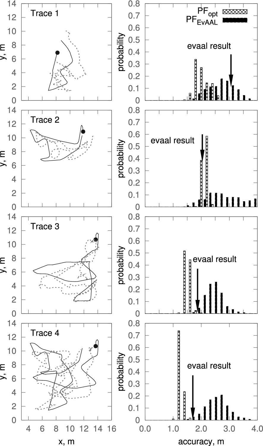
Examples of traces calculated with our improved algorithm and a comparison of the distribution of accuracy results for both
The mean accuracy of our improved algorithm
The longer the trace, the narrower the histogram for both algorithms, since for such long traces, the larger part of the trajectory is calculated with the particle filter in the converged state.
During the competition, the straightforward approach was used for AoI determination by the RealTrac localization server. Thus, an AoI event was reported to the AAL system if the object (i.e., the center of mass of all N particles representing the object) was located within the AoI.
As was noted in Section 4.3, a detailed analysis of the competition results revealed an approach to significantly improve performance of the system for AoI determination. The particle filter allows us to estimate not only the location of an object but also the posterior location density. Furthermore, it makes it possible to use this posterior density for AoI determination by calculating the relative number of particles in all AoIs.
Percentage of correct AoI determinations for two approaches
Percentage of correct AoI determinations for two approaches
Since the particle filter is a probabilistic algorithm, results of area determination vary from one run to another, much like the position calculation algorithms described in Section 4.2 and discussed in Section 6.1. Therefore, the PDF of the AoI determination results acquired in multiple runs with the same given input data adequately describes the effectiveness of the algorithm.
The results presented in Fig. 13 were acquired from 1000 runs for each AoI determination algorithm (i.e., the straightforward and improved approaches).
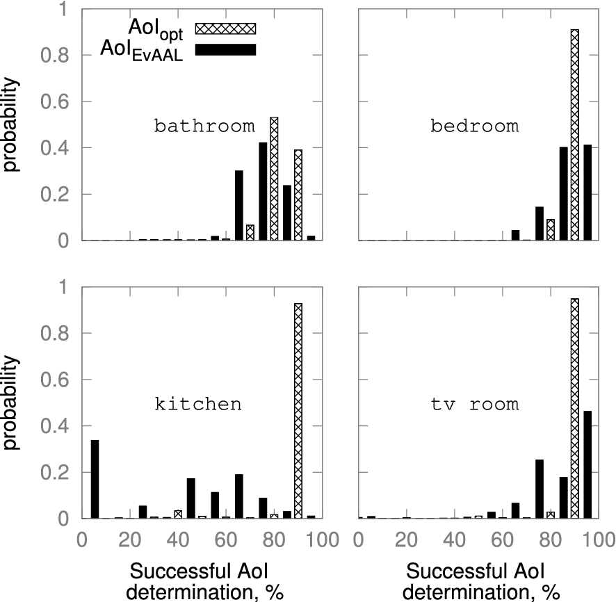
Distribution of AoI determination results; the OX axis corresponds to the correctness of AoI determination expressed as a percentage; the OY axis corresponds to the probability of the results; solid boxes indicate results generated with the straightforward algorithm used at the EvAAL-2013 competition, whereas shaded boxes correspond to the improved algorithm that uses the particle state representation.
In the figure, the OX axis corresponds to the number of successful AoI determinations relative to all attempts. The OY axis corresponds to the estimation of the probability of obtaining the given AoI determination results.
As an example, for the kitchen, the most probable result for the straightforward approach is close to zero, since the area is small and NLOS ToF errors are large. As a result, the system cannot recognize whether the object is within this area. However, using our improved algorithm
In summary, for the information presented in the plots of Fig. 13, the use of the particle representation of posterior location distribution increases the percentage of successful AoI determinations.
As mentioned above, all RealTrac equipment and software modules at the EvAAL competition used default general settings defined prior to the event. For example, localization algorithms were tuned to be used without considering the data describing walls and building contours. As another example, the maximum speed of an object was set to a very high limit of 3 m/s, which is not achieved in reality. Additionally, as yet another example, an actor was assumed to put the mobile device anywhere he or she wanted.
In fact, the mobile device was placed (and remained) in the actor’s pocket, which significantly decreased IMU inaccuracies. Furthermore, the actor walked with a predefined speed and had a certain step length that allowed a posteriori analysis to optimize step length noise. Data regarding ToF measurements in the Living Lab enabled us to estimate possible location precision and optimize the number of particles. Therefore, we suggested the approach of applying the optimized settings found by analyzing the attempts rejected at the competition (see Section 6).
The use of the optimized parameters of the particle filter
Algorithm performance
A key characteristic of the particle filter is the tradeoff between the number of particles and processing time. A larger number of particles allows us to estimate location more precisely; however, it requires more computational resources. Figure 14 illustrates the dependence of location accuracy (75% quantile of the CDF) and the average calculation time per location on the basis of the number of particles for the improved versions (both
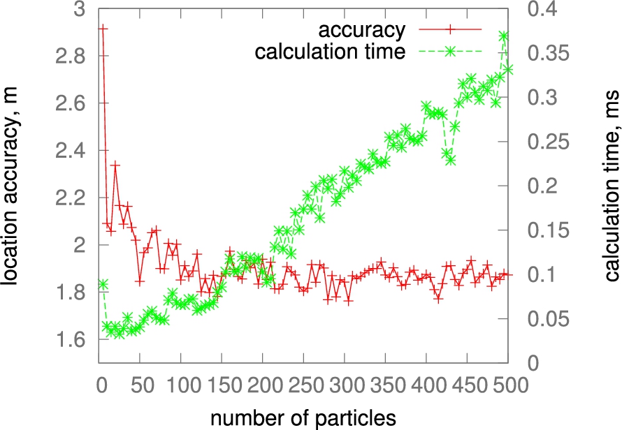
Accuracy (75% quantile of the CDF) and calculation time per location depending on the number of particles.
As shown in the figure, location error decreases significantly when the number of particles increases from five to approximately 100. For a greater number of particles, location accuracy remains approximately constant, whereas processing time linearly increases. Therefore, 100 particles were chosen as the optimal setting for the PF implementation.
The aim of this contribution was to examine results of the EvAAL-2013 indoor localization competition using experiences of the RealTrac team, which was the contest winner. A number of criteria, including positioning accuracy, availability, installation complexity, user acceptance, and integrability within AAL, differentiated our results from previous findings in the literature and the results of other competitors. This differentiation is attributed to the use of a set of special techniques and decisions of the RealTrac system.
In this paper, we showed that scores obtained at the EvAAL-2013 competition could have been higher if proper localization algorithm settings were applied. Additionally, we could achieve better results by using information from external sensors in the Smart House Living Lab provided by the organizers. For example, location-aware context events regarding actors switching the light on or off, proximity sensors, and the like might have been used for real-time corrections in positioning estimations. Unfortunately, the RealTrac team used no such information in the EvAAL-2013 competition; however, our work after the competition indicates the possibility of further improvements in localization accuracy, which was the highest weighted criterion.
Footnotes
Acknowledgements
The research described in this paper was ordered by the RTL-Service JSC and was supported by Petrozavodsk State University (within the program of the Strategic Development Program of PetrSU), the Ministry for Education and Science of the Russian Federation (contract 14.574.21.0059 and other grants), the Foundation for Assistance to Small Innovative Enterprises, and the Ministry for Economic Development of the Republic of Karelia (Russian Federation). The authors would like to thank Enago (