
Abstract
Due to the advancement in personal health care devices, healthcare monitoring of an individual at anytime and from any location becomes a reality. The major issue with most personal healthcare device is their high power consumption and frequent charging. It prevents such devices from being used in critical regions where there is no provision for continuous power or medical infrastructure. Energy harvesting is one of the methodologies extending the lifetime of a battery. This paper presents the design of an Internet of Things enabled personalized healthcare device for monitoring human vital signs. The hardware prototype is developed with a low cost Wi-Fi enabled embedded board known as NodeMCU. The NodeMCU interfaced with vital signs monitoring sensors, an activity monitoring sensor, a rechargeable battery, and a solar panel. The vital signs of a person, such as body temperature, heart rate and activity are collected in a cloud environment and an alert is sent to the caregiver under abnormal circumstances. The results show that the prototype can successfully monitor the vital signs and activity such as idle or fallen, and also the lifetime of the battery has been extended for long term use, contributing to a healthier life style.
Introduction
Internet of Things (IoT) is a new technological marvel that gains attention from vast research fields and applications in the past few years [6,10]. IoT connects network devices, allowing data about the environment to be collected for further processing. The advancements in sensors, low-power integrated circuit and wireless communication technologies make IoT an interesting choice for applications pertaining to healthcare, IoT helps to connect the patients for whom continuous monitoring is needed in hospitals or residents and the healthcare professionals seamlessly in a very efficient manner [3,4,7].
The architecture of IoT for healthcare application is shown in Fig. 1. The personal healthcare device with sensors and transceiver has the capability to collect the vital signs of the human and transmits to the gateway. Depends on the nature of application such as indoor or outdoor, and depends on the range of communication the data can be transmitted via Wi-Fi or Bluetooth. The data pushed to the cloud for the registered users and from the other end the caregivers can retrieve the data whenever needed and also the data corresponding to the person who needs to be monitored are published in the devices such as mobile phone, tablet, and personal computer of the caregivers for further decision making.

Architecture of IoT healthcare.
The personal healthcare devices are battery operated and the lifetime depends on the usage of energy. In outdoor applications such as health camp in remote places, soldier vital signs monitoring to name a few, to have a long-term usage of the device to capture the vital signs data without loss, measures need to be taken. One such solution to generate power from external source is solar light [18], and is claimed to an effective solution in applications related to healthcare.
Existing works on personal healthcare device design do not include the concept of solar energy-based energy harvesting to extend the device’s life. Solar-powered energy harvesting has already been used in wearable and wireless sensor networks in addition to the traditional battery-powered power source. This work proposes the design of an IoT-enabled personal healthcare device, with the following key contributions:
Design and development of a healthcare device for monitoring and measuring multiple human vital signs.
Utilization of a renewable energy source, specifically solar, to provide secondary power to the device.
Self-adaptive modes of operation of the device based on the nature of the operating environment.
Real-time alert to caregivers.
The remainder of the paper is organized as follows: Section 2 describes the literature survey. Section 3 explains the proposed system. Section 4 shows the experimental results. Finally in Section 5 we conclude the paper.
This section highlights the overview of existing works in the domain of IoT enabled personal health care devices.
Nautiyal and Devi [12] designed a portable IoT enabled healthcare device for data collection in rural areas. The microcontroller is interfaced with blood pressure sensor, pulse sensor, and body temperature sensor. The data are stored in a cloud platform using Wi-Fi. Each user is provided with a unique key for data saving and segregation.
Zagan et al. [19] designed an IoT based electrocardiogram monitoring device which is used for remote monitoring of cardiac patients at home. The device is designed to operate in two modes namely, selection and execution mode. The continuous monitoring helps to capture the sporadic activities if any. The electrodes associated with the monitoring device is placed by the patient in the pectoral region by the guidance of a specialist. An alert signal is generated if the electrodes are not receiving the signals properly. The signals are monitored using greencardio application which allows the real time monitoring of the signals of the patients. The device is battery operated and it is rechargeable.
In the study by Darshan and Nayak [5], a drip infusion monitoring system with electrocardiogram (ECG) signal is proposed. Moisture sensor is used in the drip container to determine the position, voice alert is given to the nurse whenever the level goes below the threshold value. The patients are provided with keypad, which is used to send the messages such as “I need water” and “Emergency”, when pressed by to the nurse. Based on the number of requests received at the nurse station, the service to the patients are prioritized based on the importance of the need.
A ubiquitous healthcare system supporting 6LoWPAN is developed by Touati et al. [17]. The Z1 motes supporting contiki operating system is interfaced with ECG, temperature and accelerometer sensors. The data from the mote is captured by the labview running at the personal computer for analysis.
Personal health care device to be used in automotive to monitor the vital signs of chronic patients is implemented by Han et al. [8]. The vital signs such as temperature, blood glucose, oxygen saturation, electrocardiogram, and plethysmogram are collected and transferred via bluetooth to the manager and then to the remote server using Wi-Fi. The data is transmitted according to IEEE11073 standards to achieve interoperability among different personal healthcare devices.
The sleep patterns of patients are studied by Saleem et al. [16]. Their system consists of Arduino connected with accelerometer, pulse oximeter, and microphone. The server stores the acquired data, and machine learning algorithm like random forest with prediction is used to classify the data and forecast future values that are relevant to a particular patient. The sleep patterns are classified as peaceful, very peaceful, medium, un-peaceful and very un-peaceful.
In the study by Kadhim et al. [9], information such as heart beat, blood oxygen, body temperature, environmental temperature, and humidity are transmitted using the Message Queuing Telemetry Transport (MQTT) protocol and made available in the cloud. The collected data is made available to the authenticated user. Data collection is accomplished through the use of a master-slave architecture in which tasks such as data collection and forwarding to the cloud are divided among them. The approach’s disadvantage is the device’s high energy consumption as a result of the use of multiple sensors.
In the study by Cao et al. [1], a cloud-based IoT health monitoring system is proposed. Vital signs like blood pressure, EEG, blood oxygen, and heart rate are measured. The transmitted data is stored in the cloud, and users can access the health records via a URL. The system includes a mechanism for the health consultant to make recommendations based on the level of vital signs collected.
An IoT-based elderly health care monitoring system is proposed by Pinto et al. [13]. The wearable device on the wristband detects falls and generates an alert in the event of an emergency. Environmental temperature, body temperature, accelerometer, and a push button are types of sensors used in the device. The collected data is viewable in a URL by the caregiver or doctor. The battery has a lifespan of 12 days before it needs to be replaced. The IoT device lifetime could be extended by modifying the state of the wearable device such as idle, active, and sleep.
Ambient-based devices around users to detect falls both during the day and at night is proposed by Ramanujam and Padmavathi [14]. The proposed solution uses retroreflective tape attached with everyday clothing. IR camera connected to a computer is used to monitor the environment and detect falls. When it is daytime, the red component of the tape is utilised to locate the position of person, and when it is nighttime, the tape’s reflections are used. The system’s high cost and user privacy concerns are the shortcomings of the system.
In the study by Ray [15], a conceptual framework named “home health hub internet of things” is proposed. It is a five-layered framework, with the sensing layer at the bottom, which addresses the biological sensor connection provision. The next layer from the bottom is the communication layer, which handles communication within a range of 10-900 m. The next higher layer is the information processing layer, which handles gateway selection. Following that is the internet application layer, which is responsible for sending data to the cloud. The user application layer is the topmost layer, where the caregiver or doctor has access to the collected data.
Proposed system
Figure 2 shows the block diagram of the proposed system. Power is transferred from the solar panel to the buck-boost converter (LTC3127) which is used to regulate the output voltage to 5V and charge the super capacitors connected to the circuit. A backup battery is connected to this system through the power path controller (LTC4412) to the voltage regulator (LTC3130-1). The power path regulator allows power to flow from the battery to the system only when the voltages of the solar panels and super capacitors are lower than the battery output voltage. The power path regulator performs this function by sending gate pulses to the P-MOSFET connected to the battery and the LTC3130-1 input. The LTC3130-1 is used to provide regulated voltage to the NodeMCU in order for it and the sensors connected to it to function properly.
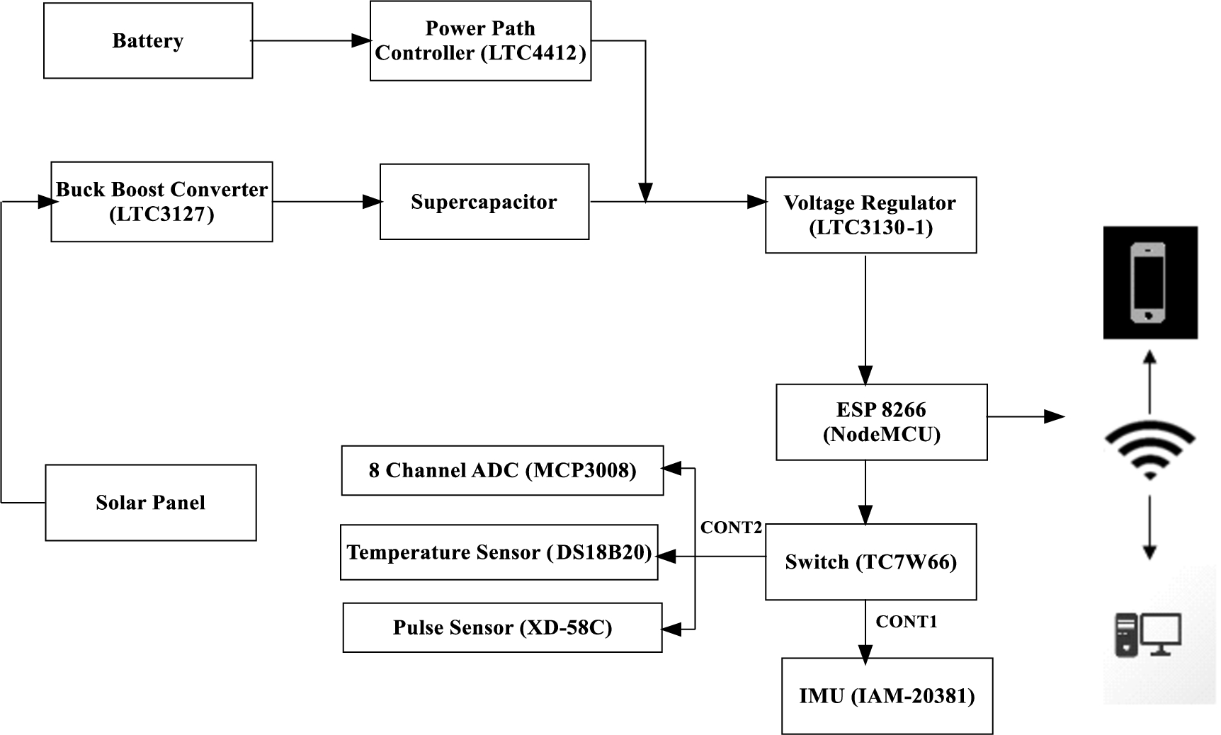
Block diagram of the proposed system.
Pulse sensor (XD-58C), temperature sensor (DS18B20), and 3-axis accelerometer (IAM-20381) are connected to the ESP8266 (NodeMCU). NodeMCU has only one analog input port and so ADC (Analog to Digital Converter) expander (MCP3008) is used to receive the multiple analog sensor outputs and relay the sensor value to the NodeMCU. The MCP3008 communicates to NodeMCU using the serial communication protocols such as Serial Peripheral Interface/Inter Integrated Circuit (SPI/I2C). Power to these sensors is controlled via the two channel switch IC (TC7W66). One of the channels (CONT2) is used to control the power to the 8 channel ADC, pulse sensor and temperature sensor when the whole device switches to the low power mode while the other channel (CONT1) is used to control the power to the accelerometer when the device transitions to deep sleep mode thereby reducing the overall power consumption during the low power and deep sleep mode. NodeMCU has inbuilt processor and it is configured in such a way that when the following conditions are met, an alert email is sent to those who are interested in the subject:
When the person’s temperature rises above the reference value or falls below the reference value.
When the person’s pulse rate rises or falls above or below the reference value set for each.
When the accelerometer value reaches the preset level.
The accelerometer’s pre-determined level is determined by assuming that when the person falls, the accelerometer value corresponding to that position is recorded and used for coding. The person can fall in a variety of positions, various assumptions are made, and the accelerometer value for each position is recorded and used in the coding section. Cayenne MQTT [11], a MQTT broker, is used for real-time data visualization and triggering. We can monitor sensor values and send trigger signals based on those sensed values.

Hardware prototype.
Figure 3 shows the hardware prototype of the personalized healthcare device for vital signs monitoring device.
NodeMCU
The NodeMCU, which collects and processes sensor data as well as performs power management to reduce overall power consumption, is the heart of the personal healthcare device. It is a low-cost microcontroller unit with a 32-bit tensilica processor that operates in the 2.5V to 3.6V voltage range. The device’s power consumption ranges from 10 microamperes to 170 milli Amperes. The device includes a TCP/IP protocol stack and supports 802.11/b/g/n.
Pulse sensor (XD-58C)
The XD-58C is a low-cost, plug-and-play Arduino compatible heart-rate sensor. The sensor attaches to a fingertip or earlobe and connects directly to Arduino. The LED shines light into the fingertip, earlobe, or other capillary tissue, and the sensor detects how much light bounces back. The operating voltage is 4 volts and the current consumption is 4 mA.
Temperature sensor (DS18B20)
The DS18B20 digital thermometer measures temperatures from 9 to 12 bits in Celsius. The DS18B20 communicates with a central microprocessor via a 1-Wire bus, which by definition requires only one data line (and ground). Furthermore, the DS18B20 can draw power directly from the data line, removing the need for an external power supply.
3-axis accelerometer (IAM-20381)

Flowchart of power mode.
The IAM-20381 is a 3-axis motion tracking accelerometer. It has a 512-byte FIFO that allows the system processor to burst read sensor data and then enter a low-power mode, thus reducing traffic and power consumption. It has a Wake-on-motion (WOM) interrupt for low power application processor operation.
Solar panel
Organic, inorganic, and organic-inorganic solar cells are deposited over flexible substrates to create lightweight, cost-effective solar modules that can be integrated into, rather than installed on, a variety of surfaces. Current conversion efficiencies under standard conditions range from 3 to 15%.
Figure 4 shows the flowchart of power flow mode. During the low power mode, the Wi-Fi modem circuit is turned off and Central Processing Unit (CPU) is suspended to save power. The system enters low power mode if there is no change in the accelerometer data for a specified period of time. In low power mode the power to the sensors are cut down. Before transitioning to the low power mode, the WOM interrupt in the accelerometer is enabled so that it can generate an interrupt when the accelerometer value exceeds a certain threshold. On receiving the interrupt, MCU switches from low power mode to normal mode. Except for the Real Time Clock (RTC), all MCU operations are suspended during deep sleep mode. When the bedtime expires or the reset signal is received, the device will awake from deep sleep and resume operation from the initial state.
Table 1 shows the current consumption of hardware components of the personal healthcare device during different modes of operation. The lifetime is calculated using the Eq. (1), omitting the battery life cycle consideration. The battery capacity is represented in milli Ampere hours (mAh) and load current is the current consumption of components in Amperes.
Table 2 shows the lifetime of a personal health care device that is powered solely by a battery and battery along with a 9W solar panel. The results show that the use of both the battery and the solar panel increased the lifetime. The power density of the sunlight determines the charging time of the rechargeable battery. It takes about 4 hours to charge the battery at noon with a clear sky, and it takes much longer to charge the battery indoors.
Current consumption of hardware components during different modes of operation
Current consumption of hardware components during different modes of operation
Battery lifetime of the personal healthcare device

Dashboard for viewing vital signs measurements.

Observation of body temperature.

Alert email to the caregiver of the person.
Figure 5 depicts the user side dashboard view, which displays the values associated with the person’s vital signs. The dashboard is set up with the help of the Cayenne server to monitor the values from sensors such as temperature, pulse and accelerometer. MQTT is the underlying application layer protocol used for communication between the personal healthcare device and the Cayenne server [2]. The protocol works on a publish subscribe mechanism to achieve asynchronous communication and low power consumption. CayenneMQTTESP8266 is a library used for implementing MQTT-based communication as well as authorization.
Figure 6 shows the user’s temperature data over a continuous time interval. This option could be used if a user requires continuous data monitoring. Certain decisions, such as whether or not to seek immediate medical attention, must be made based on unusual changes in body temperature. Whenever the user is not in the direct vicinity of the medical practitioner, and while measuring person’s temperature and if any abnormal value being detected an alert email as shown in Fig. 7 is sent to the registered caregiver to arrange for additional medication.
Figure 8 shows a user’s sensed heartbeat rate over a specific time period. Any irregular heartbeat rhythms in the 40-50 bpm range are considered abnormal, and an alert is issued to the caregiver as shown in Fig. 9. This aids in the planning of any first aid for the person who may experience abnormal heartbeat due to poor blood circulation in the body.
This paper presented the design of an Internet of Things enabled personalized healthcare device for monitoring human vital signs. Various aspects of an IoT system have been addressed, ranging from sensing, computing, and communicating to the cloud environment. Finally, the developed prototype was validated for sensing various vital signs, tracking activity, and extending battery life. The proposed system is appropriate for monitoring vital signs for people living in both urban and rural areas.
Future work will focus on developing a global positioning system enabled system to determine the best medical practitioner to provide healthcare in emergency situations.

Observation of heartbeat rate.

Alert email to the caregiver on the heart beat rate.
Conflict of interest
None to report.