
Abstract
BACKGROUND:
In the blood flow through microvessels, platelets exhibit enhanced concentrations in the layer free of red blood cells (cell-free layer) adjacent to the vessel wall. The motion of platelets in the cell-free layer plays an essential role in their interaction with the vessel wall, and hence it affects their functions of hemostasis and thrombosis.
OBJECTIVE:
We aimed to estimate the diffusivity of platelet-sized particles in the transverse direction (the direction of vorticity) across the channel width in the cell-free layer by in vitro experiments for the microchannel flow of red blood cell (RBC) suspensions containing platelet-sized particles.
METHODS:
Fluorescence microscope observations were performed to measure the transverse distribution of spherical particles immersed in RBC suspensions flowing through a Y-shaped bifurcating microchannel. We examined the development of the particle concentration profiles along the flow direction in the daughter channels, starting from asymmetric distributions with low concentrations on the inner side of the bifurcation at the inlet of the daughter channels.
RESULTS:
In daughter channels of 40 μm width, reconstruction of particle margination revealed that a symmetric concentration profile was attained in ∼30 mm from the bifurcation, independent of flow rate.
CONCLUSIONS:
We presented experimental evidence of particle margination developing in a bifurcating flow channel where the diffusivity of 2.9-μm diameter particles was estimated to be ∼40 μm2/s at a shear rate of 1000 s−1 and hematocrit of 0.2.
Introduction
More than 30 years ago, in vivo studies with use of intravital microscopy measured the distribution of platelets flowing in arterioles of the rabbit mesentery and found an excess of platelets near the vessel wall [1,2]. Following in vitro studies using latex particles of 2.38 μm diameter as a platelet substitute showed that the excess near the wall occurred for these particles as well, but it occurred only when red blood cells (RBCs) were present at the volume concentration (Ht) larger than 7% [3,4]. This enhanced concentration of platelets or platelet-sized particles near the vessel wall is called “margination” or “near-wall excess”. The margination of platelets is evidently expedient in their functions of hemostasis and thrombosis. In addition to this fact, recent findings that such a segregation in confined flows is ubiquitous for multicomponent suspensions have promoted extensive studies on this phenomenon for understanding its mechanism [5–7] as well as exploring its potential applications in relation to drug delivery system [8,9] and cell separation [10,11].
In microvessels, RBCs experience lift forces away from the vessel wall due to their deformability, and migrate toward the vessel center. As a result, a layer depleted of RBCs is formed adjacent to the vessel wall, known as the cell-free layer (CFL), and the core of the vessel is rich in RBCs (RBC core) [12]. A number of numerical simulations and model studies have elucidated that platelets in the RBC core are expelled toward the vessel wall by their random hydrodynamic interactions with surrounding RBCs as well as the volume exclusion, resulting in high concentration of platelets in the CFL [13–29]. Crowl & Fogelson [14] showed by their 2D numerical simulation that the development of platelet margination can be described as a drift-diffusion process and that, due to the presence of a net drift velocity of the platelets in the outward direction into the CFL, platelets in the CFL are prevented from reentering the RBC core. Among more recent 3D numerical studies, Zhao et al. [17] demonstrated that the velocity fluctuation in the RBC core induced by the interaction with RBCs causes platelets to migrate diffusively in the direction normal to the wall and that a mean lateral velocity of platelets further expels them toward the channel wall, leading to the excess concentration of platelets in the CFL. Hypothesizing that the platelet margination is due to the irreversible flow of platelets into the CFL, Mehrabadi et al. [23] described their numerical simulation results for blood flow in terms of the RBC-enhanced diffusion of platelets in the RBC core combined with platelet trapping in the CFL. There are many other additional notable research efforts on the topic of platelet margination (see also the references of the reviews [24,30]).
Most of the aforementioned studies concerned the movement of platelets in the RBC core, except for some studies. Vahidkhah et al. [20] investigated the platelet dynamics close to and in the CFL, by the numerical computation of the motion of RBCs and platelets subject to a simple shear flow between two parallel plates. They estimated that, in the CFL, the diffusivity in the transverse direction (along the direction of the vorticity of shear flow) would be much larger than that in the wall normal direction. Krüger [25] also pointed out the strong anisotropy in platelet motion in the CFL by their 3D numerical analyses for RBCs and platelets flowing through circular tubes at Ht ≈ 0.37.
The diffusive motion of platelets in the CFL originates from 3D nature of the hydrodynamic interaction among platelets and RBCs flowing at the edge of the RBC core. In vivo experiments showed that the interface between the RBC core and the CFL exhibited significant temporal and spatial variations in the arterioles [31,32]. This phenomenon was reproduced by 3D numerical simulations for blood flow [22,25,33], suggesting a frequent occurrence of the hydrodynamic interaction between the outermost RBCs in the RBC core and platelets in the CFL. Such random 3D interactions could generate diffusive behavior of platelets in the CFL. Although the diffusion of platelets was anticipated, particularly, in the transverse direction as pointed out by Vahidkhah et al. [20], there have been no experimental quantification of the transverse movement of platelets in the CFL. Evidently, the dynamics of platelets in the CFL is important in understanding the initial mechanical process of thrombus formation, since it affects the probability of platelet-wall interaction [34–36].
In the present study, we performed in vitro experiments to present the evidence of the transverse movement of platelet-sized particles in the CFL. For platelet-sized particles immersed in RBC suspensions flowing through a Y-shaped bifurcating channel with rectangular cross-sections, we measured the particle concentration profile across the channel width near the bottom face in the parent channel as well as in the daughter channels.
Figure 1(a) shows a schematic of the Y-shaped bifurcating channel, and Fig. 1(b) represents expected cross-sectional views and particle concentration profiles for the RBC suspension flow through the parent channel and daughter channels. Figure 2 shows the Y-shaped bifurcating flow channel used in the present experiment. In the parent channel, the margination of particles develops so that the particles are concentrated near the channel walls when they reach the inlets of the daughter channels. Reflecting this preferential distribution of particles, the particle concentration at the inlet of daughter channels would be high adjacent to the channel wall on the outer side of the bifurcation while it would be low on the inner side of the bifurcation. Starting from this asymmetric distribution of particles at the inlet, the particle distribution in the daughter channels is expected to develop in the flow direction, approaching a symmetric distribution between the inner and outer sides of the bifurcation. This reconstruction of the margination is caused by the transverse movement of particles in the CFL, across the channel width from the outer side of the bifurcation to the inner side (see arrows in Fig. 1(b)).
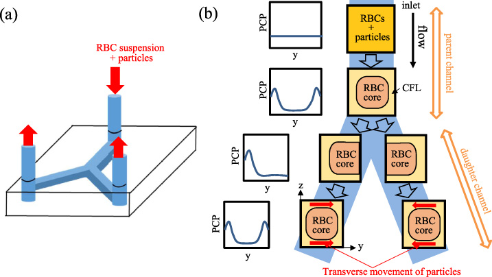
(a) Schematic of Y-shaped bifurcating channel with rectangular cross-sections, and (b) expected cross-sectional views and particle concentration profiles (PCP), for the RBC suspension flow through the parent channel and daughter channels. We measured the particle concentration profile across the channel width (y-direction) near the channel bottom face (z = 5.7 μm from the bottom).
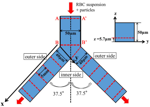
Top view and cross-sectional view of Y-shaped bifurcating microchannel. The measurement sites are indicated by dashed lines.
The present study was aimed at examining this development of the particle concentration profile in the daughter channels, by measuring the transverse (y-) distribution of particles at various distances from the bifurcation. We made a fluorescence microscope observation near the bottom face of the channel to detect fluorescent particles in the RBC suspension flow. From the development of the particle concentration profile in the daughter channels, we estimated the diffusivity of the particles in the transverse (y-) direction across the channel width.
All of the procedures were performed according to the ethical policy of Kansai University. Fresh human blood was sampled from young healthy volunteers and used within four hours after collection. The RBCs were washed three times by centrifugation (Model 2410, Kubota, Japan) in phosphate buffered saline (PBS). PBS containing 1% bovine serum albumin (Wako, Japan) and 5% dextran (Dextran 40000, Wako, Japan) was used as a suspending medium, which has density of 1.03 × 10³ kg/m3 and viscosity of 2.50 × 10⁻³ Pa s at room temperature (22 °C). RBCs were suspended in this medium at Ht = 0.2. Dextran of higher molecular weight (70 k–1000 kDa) is known to cause RBC aggregation. Dextran of 40 kDa at 5 wt% used in the present study does not cause RBC aggregation [37]. We confirmed the absence of RBC aggregation in the suspension by bright field observation. Spherical, fluorescent polystyrene particles with mean diameter of 2.9 μm and density of 1.05 × 10³ kg/m3 (Estapor F-XC300) were added to the RBC suspension at the volume concentration of ∼0.1%. The excitation and emission maxima of fluorescence are ∼475 nm and ∼525 nm, respectively.
Figures 2 and 3 show the Y-shaped bifurcating flow channel (Yodaka, Japan) and the experimental setup, respectively. The flow channel was made of polydimethylsiroxane (PDMS) and its bottom face was sealed with a glass coverslip for observation using an inverted fluorescence microscope, as shown in Fig. 3. The parent channel has a square cross-section of 50 μm width × 50 μm height and length of 10 mm, and the daughter channels have a rectangular cross-section of 40 μm width × 50 μm height and length of 30 mm. Each outlet of the daughter channels was connected to a syringe and suspension flow was induced by a syringe pump (KDS270, KD Scientific) at constant flow rates of Q = 0.5, 1.0 or 2.0 μl/min. If we assume the flow of a Newtonian fluid, the corresponding average wall shear rates at the bottom face in the daughter channels are ∼630, 1300 and 2500 s−1, respectively. The Reynolds numbers in terms of the average flow velocity and the hydraulic diameter of the daughter channels are 0.08, 0.15 and 0.3, respectively, indicating that the inertial effect is negligible.

Confocal laser scanning microscope and high speed camera system.
The fluorescent particles flowing through the microchannel were observed with a confocal laser scanning microscope system, consisting of an inverted microscope (IX71, Olympus, Japan) with a 40 × oil immersion objective (UPLSAPO40XS, Olympus, Japan), a confocal scanning unit (CSU-X1, Yokogawa, Japan), a laser source (Sapphire 488, Coherent) and a high-speed camera (AX50, Photron, Japan) equipped with an image intensifier (C9016-21 Hamamatsu, Japan), as shown in Fig. 3. The focal plane was set at a height of z = 5.7 μm from the channel bottom face. Fluorescence observation and recording was made at the channel inlet (AA’ in Fig. 2) and 10 mm downstream from the inlet (just before the bifurcation) (BB’ in Fig. 2) in the parent channel, and at several distances from the bifurcation in the daughter channels (x = 0 ∼ 25 mm). The images were recorded at a rate of 500 frames per second for 8 seconds. The pixel size of the image was 0.41 μm × 0.41 μm.
For a micrographic image, the transverse (y-direction) position of each fluorescent particle was counted with use of an image analysis software ImageJ (NIH). We performed this procedure on one frame for every 50 frames of consecutive images and obtained the distribution of particle number across the channel width. Figure 4(a) shows an example of the image obtained in the parent channel. In order to detect the position of the channel walls, we obtained the image of the aqueous solution of sodium fluorescein (C20H10Na2O5, fluorescent dye) flowing through the channel (Fig. 4(b)). Figure 4(c) shows the profiles of the fluorescence intensity I and its derivative dI∕dy in the rectangular region of the sodium fluorescein image shown in Fig. 4(b). Figure 4(c) indicates that the derivative profile has two clear (positive and negative) peaks, the y-positions of which were considered the wall positions. The wall positions thus determined are shown by vertical solid lines in Fig. 4(a). In this case, the channel width between the two vertical lines was 49.6 μm for the parent channel. In the present experiments, channel width thus obtained was in the range within ±1.5 μm from the nominal width (50 μm for the parent channel and 40 μm for the daughter channels). The y-coordinates of the particle centers detected were normalized with respect to the measured channel width and rescaled to the nominal channel width.
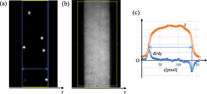
(a) An example of the fluorescent image of particles in the parent channel, (b) the image of the aqueous solution of sodium fluorescein (C20H10Na2O5, fluorescent dye) flowing through the channel, and (c) the fluorescence intensity I and its derivative dI∕dy in the rectangular region of the image (b). The unit of the vertical axis is arbitrary.
The particle concentration profile was normalized by the total number of particles recorded, and represented by a histogram, with its bin width of 2 μm. In the parent channel, the histograms were symmetrized with respect to the center, considering spatial symmetry. In the daughter channels, the histograms acquired on the right-hand side branch were inverted with respect to the center and averaged with the histograms on the left-hand side branch at the same distance from the bifurcation. In the following figures, each histogram represents the average value and standard deviation.
Figure 5 shows the concentration profiles of the particles across the channel width in the parent channel in the case of Ht = 0, measured (a) at the channel inlet (AA’ in Fig. 2) and (b) at 10 mm downstream from the inlet (BB’ in Fig. 2). Figures 5(a) and (b) show nearly uniform distributions, indicating that the particles entered the channel inlet randomly and that the particles exhibited no margination in the absence of RBCs in the downstream cross-section. Aarts et al. [38] reported that platelets flowing through 3 mm-diameter tubes at Ht = 0 migrated to the radial position of 0.6 times the tube radius. This phenomenon can be attributed to the inertial effect which exerts the lift force on the platelets in the outward direction at finite Reynolds numbers. In fact, the Reynolds numbers for the experiments of Aarts et al. [38] ranged from 80 to 400. On the other hand, the Reynolds numbers in the present experiments were low (<1) and comparable to those for the blood flow through microvessels, so that such inertial effects were negligible.

Particle concentration profiles in the parent channel at Ht = 0, measured (a) at the channel inlet (AA’), and (b) at 10 mm downstream from the inlet (BB’) (flow rate = 1 μl/min, n = 3). The histogram represents the average value and standard deviation.
Figure 6 shows the particle concentration profiles in the parent channel at Ht = 0.2, measured (a) at the channel inlet (AA’ in Fig. 2) and (b)–(d) at 10 mm downstream from the inlet (BB’ in Fig. 2) for various flow rates. Similarly to Fig. 5(a), the uniform distribution in Fig. 6(a) indicates that the particles entered the channel inlet randomly even in the presence of RBCs. This feature was observed for all flow rates examined.

Particle concentration profiles in the parent channel, measured (a) at the channel inlet (AA’) and (b)–(d) at 10 mm downstream from the inlet (BB’) (n = 5). The flow rates are (a) 1.0 μl/min (Q = 0.5 μl/min), (b) 1.0 μl/min, (c) 2.0 μl/min (Q = 1.0 μl/min), and (d) 4.0 μl/min (Q = 2.0 μl/min).
Figures 6(b)–(d) represent the particle concentration profiles (averaged over 5 runs) across the channel width measured at 10 mm downstream from the channel inlet (BB’ in Fig. 2) at Ht = 0.2 for the flow rates of 1.0, 2.0, and 4.0 μl/min, respectively. These figures indicate that the particles exhibited significant margination in the downstream cross-section at Ht = 0.2. Peak values of the particle concentration seem to increase with increasing flow rate. In order to estimate quantitatively the extent of the near-wall excess in these cases, we introduced an index “Rw”, which is defined as the number fraction of particles lying within 10 μm from the channel wall. For each histogram shown in Figs 6(b)–(d), we calculated Rw by summing the probability of five bins adjacent to the wall. Note that Rw = 20% for a uniform distribution of the particles. Figure 7 represents Rw for the particle distributions shown in Figs 6(b)–(d), showing an increase in Rw with the flow rate. An increase in the margination with the shear rate agrees with previous in vitro studies for straight channels [3,7].
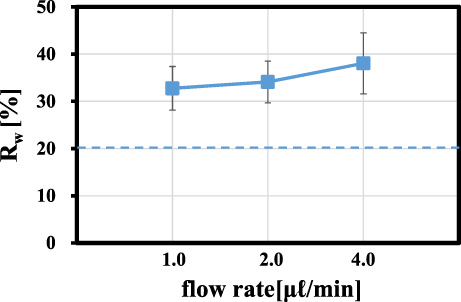
Fraction of the particle number, Rw, lying within 10 μm from the channel wall in the parent channel (10 mm from the inlet (BB’), Ht = 0.2).
Figures 8–10 show the developments of the particle concentration profile (averaged over 5 runs) in the daughter channels, at the flow rate of Q = 0.5, 1.0 and 2.0 μl/min, respectively. Note that the left and right ends of the y-axis in each histogram correspond to the channel walls on the outer side and inner side of the bifurcation, respectively. As already seen in Figs 6(b)–(d), the particles show significant near-wall excess in the parent channel just before the bifurcation in all cases. Figures 8–10 indicate that, reflecting this preferential distribution in the parent channel, the particle concentration at the inlet of the daughter channel (x = 0) was high near the outer wall of the bifurcation, whereas it was low in the remaining y-range. As the measurement sites became downstream, the particle concentration near the outer wall gradually decreased whereas the particle concentration near the inner wall gradually increased. This trend continued until the histograms became nearly symmetric with respect to the center at x = 25 mm. These features of the development of the particle concentration profile were common for all flow rates shown in Figs 8–10.
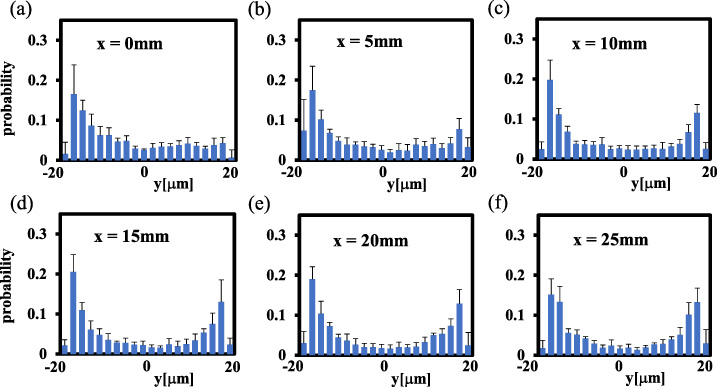
Particle concentration profiles in the daughter channels for Q = 0.5 μl/min, at (a) x = 0 (inlet of the daughter channel), (b) x = 5 mm, (c) x = 10 mm, (d) x = 15 mm, (e) x = 20 mm and (f) x = 25 mm. The histograms in the right-hand side branch were inverted with respect to the centerline and averaged with the histograms in the left-hand side branch at the same distance (x) from the bifurcation (n = 5).

Particle concentration profiles in the daughter channels for Q = 1.0 μl/min, at (a) x = 0 (inlet), (b) x = 5 mm, (c) x = 10 mm, (d) x = 15 mm, (e) x = 20 mm and (f) x = 25 mm (n = 5).

Particle concentration profiles in the daughter channels for Q = 2.0 μl/min, at (a) x = 0 (inlet), (b) x = 5 mm, (c) x = 10 mm, (d) x = 15 mm, (e) x = 20 mm and (f) x = 25 mm (n = 5).
To detect quantitatively the development of the particle concentration profile in the daughter channels, we summed the probability of every five bins (10 μm width) from the outer wall, and defined them as R 1, R 2, R 3 and R 4, respectively, as shown in Fig. 11(a). Figures 11(b)–(d) show the developments of these values as a function of distance from the bifurcation (x) at Q = 0.5, 1.0, and 2.0 μl/min, respectively. In all cases of the flow rate, R 1, the number fraction of the particles located within 10 μm from the outer wall, was high at x = 0 and decreased in the flow direction. The values of R 2, R 3 and R 4 were low and comparable at x = 0. R 4, the number fraction of the particles located within 10 μm from the inner wall, increased monotonically with x, whereas R 2 and R 3 decreased slightly.

(a) The definitions of R 1, R 2, R 3 and R 4, and their variations with the distance from the inlet of the daughter channels at the flow rate of (b) Q = 0.5 μl/min, (c) Q = 1.0 μl/min, and (d) Q = 2.0 μl/min (n = 5).
Since R 1 decreased monotonically and R 4 increased monotonically in the flow direction, these two variations with x were approximated with linear functions, respectively, and the x value of their intersection was defined as x L . The x L value represents a characteristic distance from the bifurcation, at which symmetric margination of particles has completed in the daughter channels. The x L values are plotted in Fig. 12 for Q = 0.5, 1.0, and 2.0 μl/min. Figure 12 indicates that x L ∼ 30 mm, independent of flow rate. Since the development of the particle concentration profiles in the flow direction shown in Figs 8–10 is supposed to originate from the transverse (y-direction) movement of particles toward the inner side of the bifurcation, the present result of nearly constant x L suggests that the velocity of the particle movement in the transverse direction (y-direction) is proportional to the bulk velocity of the flow along the channel axis (x-direction).

Estimated distance x L from the inlet of the daughter channel to complete the symmetric margination of the particles.
Focusing on a plane near the bottom face of the daughter channels, we observed the transverse concentration profiles of platelet-sized particles which were located mainly in the CFL. Thus, the developments of R 1 ∼ R 4 values in the flow direction reflect the transverse movement of the particles within the CFL, toward the inner side of the bifurcation. We consider this movement occurred as a result of the diffusion of the particles in the CFL.
The diffusive motion of particles in the CFL could originate from their random hydrodynamic interactions with RBCs flowing at the edge of the RBC core, as noted in Introduction. With respect to the particle diffusion in a suspension flow subjected to shear, Eckstein et al. [39] and Leighton & Acrivos [40] investigated experimentally the self-diffusion of particles, and Zydney & Colton [41] developed a model for augmented particle transport based on the shear-induced collision diffusion mechanism. These pioneering studies have shown that particles in suspension shear flows move diffusively with the diffusivity increasing with the square of the particle radius and linearly with shear rate.
Accordingly, in the present study for the diffusion of particles within the CFL, we assume that the particle diffusivity in the y-direction is expressed as
It is well known that the particle displacement Y in the y-direction within time t is given by 〈Y
2〉 = 2D
yy
t, where the bracket represents the ensemble average. Here, as t, we adopt the time for the particles placed at height z from the channel bottom to travel a distance x
L
, so that
For a particle with diameter d = 2.9 μm suspended in a fluid with viscosity 𝜇 = 2.50 × 10⁻³ Pa s at temperature T = 295 K, the molecular diffusivity is estimated to be
There have been a number of experimental and numerical studies on the margination of platelets or platelet-sized particles in blood flow through microchannels. Most of them focused on the migration of platelets or particles in the RBC core. Goldsmith and his coworkers made extensive measurements of the motion of 2 μm latex spheres in ghost red cell suspensions at Ht = 0.2 ∼ 0.7 [42]. From these measurements they estimated the dispersion coefficient of the particles defined as D
∗ = 〈𝛥r
2〉∕2𝛥t, where 〈𝛥r
2〉 represents the mean square radial distance traveled by the particle in a time interval 𝛥t, and obtained D
∗∼ 1–20 μm2/s at
Recent numerical studies also provided a wealth of information on the margination. Kumar & Graham [43–45] showed for the channel flow of binary suspensions of stiff and floppy particles or large and small particles that the hydrodynamic interaction between different components resulted in the eventual movement of stiff particles or small particles toward the channel wall. Since platelets are both stiffer and smaller than RBCs, their simulation could account well for the margination of platelets in the RBC suspension flow. A direct numerical simulation by Mehrabadi et al. [26] pointed out a more significant effect of rigidity compared to size in the binary suspension of RBCs and platelets. Focusing on the margination of platelets, Crowl & Fogelson [14] conducted a 2D computation using the lattice Boltzmann method to obtain the diffusivity ∼200 μm2/s for platelets in the RBC core at
In contrast to numerous estimates of platelet diffusivity within the RBC core, its estimate in the CFL are limited. Vahidkhah et al. [20] showed that, in the CFL, the diffusion of platelets in the transverse direction was more significant than that normal to the tube wall. Figure 3(a) of their paper [20] indicated that the platelet diffusivity in the transverse direction in the CFL was only slightly smaller than that in the RBC core, which was ∼30 μm2/s at
The variation of the flow rate affects certainly the dynamical behavior of RBCs. An increase in flow rate increases the shear stress acting on RBCs, which would induce more deformation. It also increases the frequency of hydrodynamic interactions among RBCs, which would enhance the dispersion of RBCs in the RBC core. The effect of shear rate on the RBC behavior may be evidently seen in the variation of the CFL thickness, which would be determined by a balance between the inward migration of RBCs due to the lift forces acting on deformed RBCs and the expansion of the RBC core due to the hydrodynamic interactions among RBCs. In fact, in vivo experiments reported that an increase in shear rate slightly decreased the thickness of the CFL for the arterioles in the rat cremaster muscle [31,32]. Although this tendency was reproduced by a numerical study at low shear rates (≲60 s−1) at Ht = 0.45 [33], some other numerical studies predicted slight increase or insensitivity of the CFL thickness to shear rate [15,17,22,26,28]. Katanov et al. [22] showed that the CFL thickness generally increases with shear rate, due to enhanced deformation and inward migration of RBCs, but it becomes nearly constant at relatively higher shear rates between ∼100 s−1 and ∼300 s−1. Krüger [25] predicted a similar trend up to ∼2,500 s−1. In vitro experiments of Kameneva et al. [46] in 100 μm square channels also showed that the CFL thickness at Ht = 0.2 exhibited an increase with shear rate at low shear rates, followed by a slight increase at high shear rates up to ∼67,000 s−1. The feature of weak dependence of the CFL thickness on shear rate may contribute to the present experimental results that the distance x
L
to complete the symmetric margination of platelet-sized particles, or the dimensionless constant k for the particle diffusivity
Additional experiments measuring the particle distribution at z = 24.7 μm near the mid-plane of the cross-section showed that the particle concentration profiles in the y-direction in the most downstream cross-section at x = 25 mm were nearly symmetric with respect to the centerline. This result suggests that the particle margination would be completed at x ∼ x L , not only near the channel bottom face but also over the whole cross-section, including the CFL adjacent to the inner channel wall of the bifurcation. The margination of particles into the CFL along the inner channel wall may be induced by the lateral migration in the RBC core toward the inner channel wall as well as the transverse migration (diffusion in the z-direction) in the CFL. Such lateral and transverse movements of particles as well as reconstruction of RBC core in the bifurcated flow region can be considered as a transient process from the blood flow in the parent channel to the flow in the daughter channels.
In the present study, we presented experimental evidence consistent with lateral and transverse movement of platelet-sized particles to near-wall cell-depleted regions at a bifurcation, for the first time to our knowledge. We also indicated that the transverse diffusivity of particles in the CFL could be three orders of magnitude larger than the molecular diffusivity and comparable with the diffusivity in the RBC core, so that it could affect substantially the interaction of platelets with the channel wall.
Conclusions
We performed in vitro measurements of the transverse distribution of platelet-sized particles immersed in RBC suspensions, and explored the reconstruction of the particle margination in the daughter channels of a Y-shaped bifurcating microchannel. The development of the particle concentration profiles in the flow direction indicated the movement of particles from the outer side of the bifurcation to the inner side in the CFL. This provided the experimental evidence of the transverse movement of the platelet-sized particles in RBC suspension flow. In addition, transverse and lateral movement of particles to complete the particle margination over the cross-section of the daughter channels was suggested. From the measurements, we estimated the diffusivity of 2.9-μm diameter particles ∼40 μm2/s at the shear rate of 1000 s−1 and Ht = 0.2.
Footnotes
Acknowledgements
The authors thank Mr. A. Noguchi and Mr. K. Sai for technical assistance. This research was partially supported by JSPS KAKENHI 20H02072 and the ORDIST Group Fund at Kansai University.