
Abstract
Keywords
Introduction
Periprosthetic femoral fracture (PFF) is a serious complication of total hip arthroplasty (THA), and is often associated with poor outcomes [1]. Risk factors for PFF include osteoporosis, femoral stem design and surgical technique [2,3]. Higher rates of PFF are observed with cementless fixation [4,5]. The use of cementless fixation is increasing in much of the world and this trend may continue with cementless implants showing excellent long-term success rates [6–8] and decreased operating time [9]. This will likely result in an increased prevalence of PPF. A further increased prevalence of PFF will be observed as the patient population with hip replacements rapidly increases, this will be driven by an ageing population and a trend toward early intervention hip arthroplasty. Additionally, broadening of the indications for hip replacement has led to younger patients, who are at greater risk for high-energy trauma events, undergoing the procedure [4]. Overall the prevalence of PPF will increase and efforts to reduce the risk are needed.
Based on the timing of the fracture, PFFs are classified as intraoperative, early postoperative and late postoperative, with unique mechanics involved in each situation [4]. Intraoperative PFFs can occur at any time during the surgical preparation; however, they most commonly occur during implant insertion as the surgeon strives to obtain the firm initial press fit, which is required to promote bony ongrowth and achieve long-term fixation [10–12]. To achieve the required firm press fit, the stem is pressed into the femur with considerable forces causing a wedging effect and the hoop stresses thus generated can become too great for the bone to resist [4]. A minor episode of trauma is cited as the most frequent cause for postoperative PFFs [5,13].
Postoperative PFFs occur due to anatomic forces resulting from the patient’s own weight bearing and muscle loads. Mabry et al. suggested that early postoperative fractures (3 months post-implantation) may be the result of an undiagnosed intraoperative fracture, which decreases the load-bearing capacity of the bone. The prosthesis–bone interface mechanics in the early postoperative period differ from those in the late postoperative period [4].
During the early postoperative period, bony ongrowth has not yet occurred and the prosthesis is supported only by the frictional loads arising from the initial press fit. If these supporting frictional loads are overcome, the prosthesis may wedge further into the canal, increasing the hoop strains on the femur, thereby leading to a fracture. The mechanics of the construct are quite different once bony ongrowth occurs. A much greater load is required to overcome the prosthesis–bone interface, which can be achieved only by fracturing the bone at the interface. Often, late-stage PFFs occur in conjunction with loosening of the prosthesis or loss of bone due to osteolysis or unfavorable remodeling responses [14].
The ABG II prosthesis (Stryker Orthopaedics, Mahwah, NJ, USA) is a cementless implant with a grit-blasted hydroxyapatite-coated proximal ongrowth surface with proximal medial scales and a polished distal stem, and has a successful clinical history [15–17]. For the purpose of this study sequential design changes were made to the ABG II-standard implant: the first was lack of medial scales (hereafter referred as ABG II-NMS) and the second was a high-friction titanium plasma-sprayed proximal coating (hereafter referred as ABG II-plasma).
The key focus of this study was to compare these implants, ABG II-NMS and ABG II-plasma, to the ABG II-standard implant to determine if the modification of design could decrease the risk of PFF in the intraoperative and early postoperative periods. Femoral fractures were simulated by using biomechanical loading to determine if either of the 2 changes to the ABG II femoral stem design would primarily increase the load-bearing capacity of the femur and also decrease the proximal surface strains on the femur during broaching, implant insertion, and early weight bearing, thereby improving implant longevity and durability.
Methods
Femoral specimens
The experimental testing procedure was approved by the local ethics committee/Institutional Review Board. Twelve cadaveric femurs (6 left and 6 right, matched pairs) of donors with a mean age of 61 years (range, 39–77 years) were sourced from the International Institute for the Advancement of Medicine (IIAM Corporate, Jessup, PA, USA). The femurs were subjected to X-ray and then computed tomography (CT) evaluation in the anteroposterior (AP) and mediolateral (ML) planes to ensure that they were free of pathology and to allow preoperative templating for determining the expected prosthesis sizes for the ABG II femoral components. After templating, the femurs were sectioned and potted in a polymethylmethacrylate (PMMA) potting medium, 30 mm distal to the expected position of the distal tip of the prosthesis for the template size. Each femur was cleaned off of all soft tissue. Strain gauge locations were prepared by defatting with propan-1-ol, sanding with fine grade sandpaper, re-defatting using propan-1-ol, and finally, neutralizing with a light detergent. Five rosette strain gauges (TML Co. Ltd, Tokyo, Japan) were attached to each femur anterolaterally (AL), anteromedially (AM), medially (M), posteromedially (PM) and posterolaterally (PL) (Fig. 1). A mechanical testing jig was prepared to orient the bone 9 degrees in the sagittal plane and 10 degrees in the coronal plane in order to closely replicate the anatomic loading of femoral stems (ISO 7206-4, 2010 specifications).
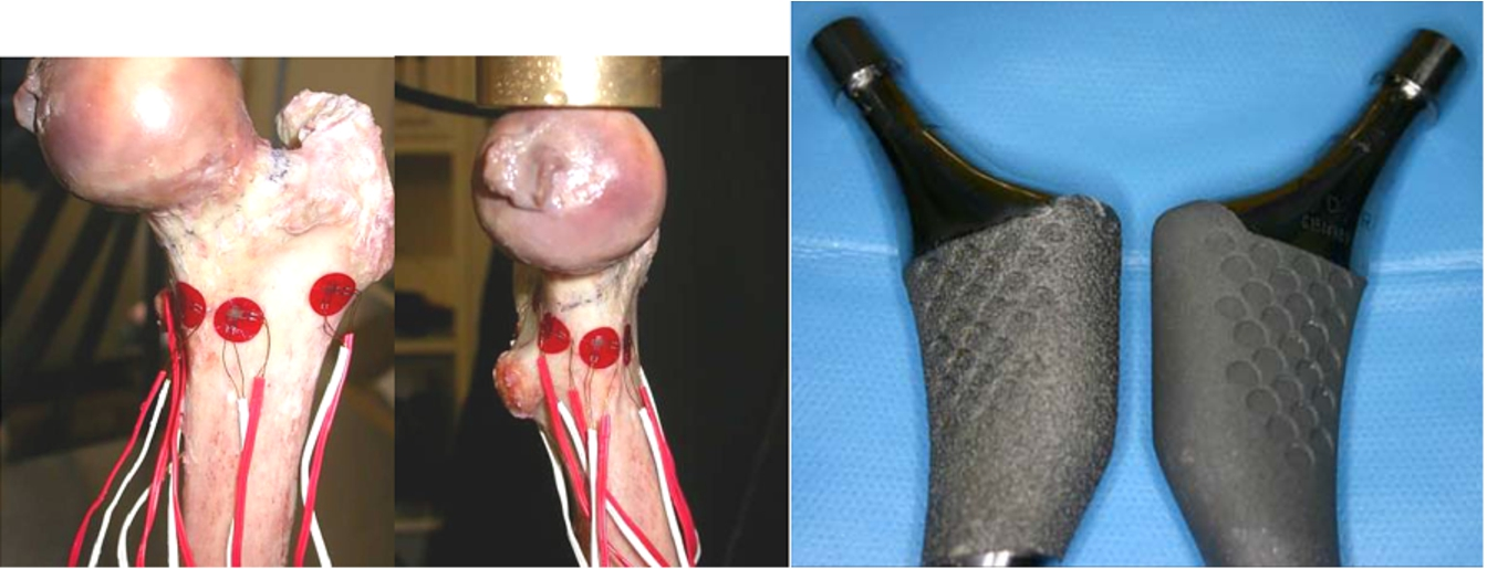
Anterior and medial views of a cadaveric femur with the 5 rosette strain gauges attached anterolaterally, anteromedially, medially, posteromedially and posterolaterally around the proximal femur. Images of the ABG II-plasma (left) and the ABG II-standard (right) implants. Note the greater surface roughness on the ABG II-plasma implant. (Colors are visible in the online version of the article;
Strain gauge rosette 1 was placed at the thinnest edge of the osteotomy in the region of the trochanteric fossa. Gauge 2 was placed 23 mm posteromedially mm from gauge 1 at the edge of the osteotomy. Gauge 3 was placed on the anterior aspect of the femur 17 mm distal as well as lateral to the most medial aspect of the osteotomy. Gauge 4 was placed 22 mm lateral and 10 mm superior to gauge 3. Gauge 5 was placed on the inferior aspect of the femur. Each rosette gauge measured the strain directly about 3 axes which were oriented such that the axial, shear and hoop strain were measured directly on each bone.
Prostheses
Two types of experimental prostheses were manufactured by Stryker Orthopaedics Mawah: (i) ABG II-plasma – an experimental ABG II femoral stem with a high-friction plasma-sprayed titanium proximal ongrowth surface (Fig. 1) and (ii) ABG II-NMS – an experimental ABG II femoral stem identical to the commercially available ABG II stems but without the medial scales being machined into the stem during manufacture. As controls, we used off-the-shelf standard ABG II stems that have a proximal hydroxyapatite coating on a grit-blasted titanium surface with proximal scales.
Biomechanical testing
The strains across each gauge were measured at 4 separate time periods using an MTS 858 mechanical testing system and simulation apparatus (MTS Systems Corporation, Eden Prairie, MN, USA): (i) native femoral strain was recorded before surgery (Fig. 2); (ii) surgical preparation strains were recorded specifically as the canal was broached to receive the prosthesis; (iii) stem insertion strains were recorded as the definitive prostheses were inserted into the canal; and (iv) strains were measured following the insertion of each femoral stem (Fig. 2). At the first and last time points, a cyclic load of 80–800 N was applied to the femur. The femurs were then loaded to failure with the implants in situ. Strains at failure were not recorded. The procedure and order of testing are depicted in Fig. 3.

Intact instrumented femur and the implant loaded under compression in the MTS testing system. (Colors are visible in the online version of the article;

Flowchart for the order of testing.
The strain signals across all 5 rosette gauges (15 strain channels) were simultaneously measured at a sampling rate of 50 Hz for the intact bone during broaching and on insertion of the femoral stem (Labview; National Instruments, Austin, TX, USA). Following the insertion of each femoral stem, strain and force–displacement data were simultaneously measured during cyclic loading of the femur (1 Hz, 50 cycles, sinusoidal, −80 N to −800 N (
Differences between groups were determined using analysis of variance. Comparison between groups was made using a least significant difference post-hoc test, with a p value of <0.05 set as significant.
Results
One of the femurs with the ABG II-plasma implant fractured during insertion; therefore, only 5 pairs have been reported for that group.
ABG II-plasma versus ABG II-standard
Implant height after impaction
There was significant variation in the seating of the implants when compared to the final broach position. In 5 out of 6 bones analyzed, both ABG II-plasma and ABG II-standard were seated higher than the broach. In the remaining bone, both the implants were seated lower than the broach. On average, ABG II-plasma was seated 0.3 mm higher than ABG II-standard (maximum, 1 mm) (Fig. 4).
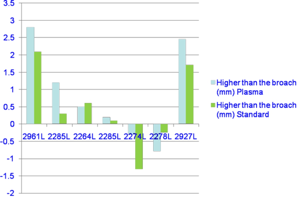
Implants heights after impaction. (Colors are visible in the online version of the article;
The maximal impaction cortical hoop strain across all the gauges was lower (less tensile) with the ABG II-plasma stem than with the ABG II-standard stem. The difference was significant in 4 out of 5 gauges, namely, the PM gauge (
Strain sensitivity
The hoop strain measured in the ABG II-plasma stem was closer to that of intact bone; the modified design was significantly less tensile than ABG II-standard based on the measurements from the M (
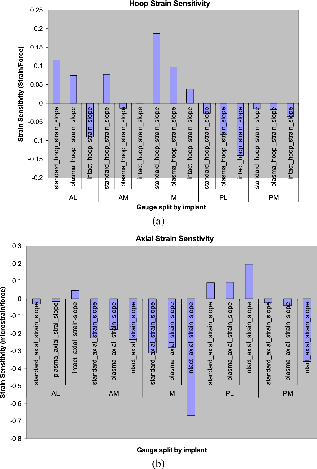
(a) Comparison of hoop strain sensitivity between the ABG II-plasma and ABG II-standard implants. (b) Comparison of axial strain sensitivity between the ABG II-plasma and ABG II-standard implants. (Colors are visible in the online version of the article;
In 3 out of 5 gauges, the final residual hoop strains of the ABG II-plasma stem were lower than those of ABG II-standard and closer to those of intact bone. However, these values were statistically significant only for the AL (
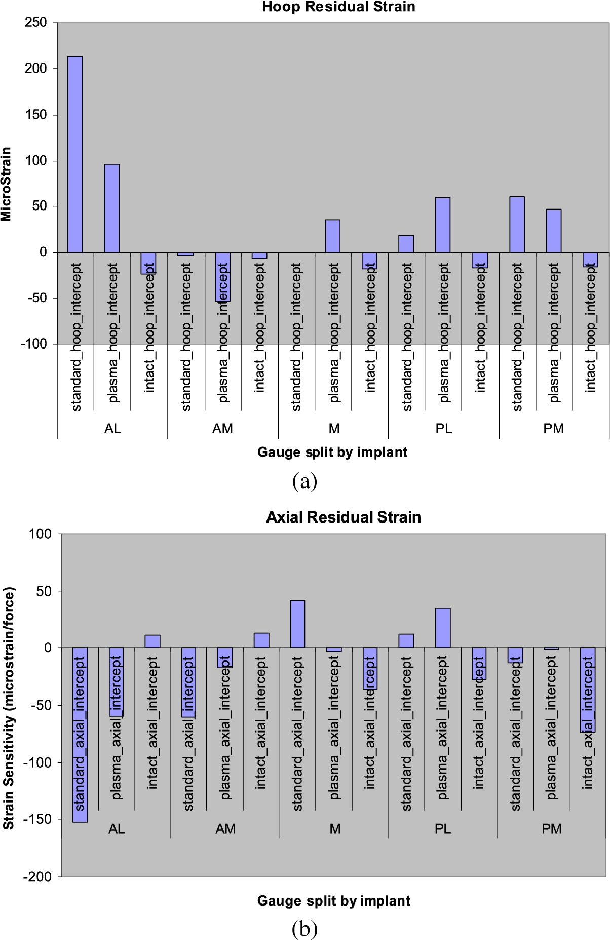
(a) Comparison of hoop residual strains between the ABG II-plasma and ABG II-standard implants. (b) Comparison of axial residual strains between the ABG II-plasma and ABG II-standard implants. (Colors are visible in the online version of the article;
The mean strain measured in the PL gauge for ABG II-plasma was significantly lower (
Failure load
Maximum failure load for ABG II-plasma and ABG II-standard implants
Maximum failure load for ABG II-plasma and ABG II-standard implants
Note:
A close correlation between the cortical index and the failure load was shown for both the ABG-standard and the ABG-plasma. For the same cortical index the ABG-plasma had a greater failure load than the ABG-standard (Fig. 7).
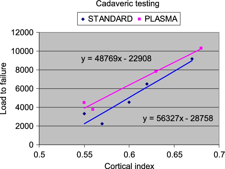
Failure load versus cortical index for the ABG II-plasma and ABG II-standard implants. (Colors are visible in the online version of the article;
There was no significant difference for the maximum impaction strains between the ABG II-NSM and the ABG II-standard across all five gauges. There was no significant difference in the implant height between ABG II-NMS and ABG II-standard. There was no statistically significant difference in the residual strain between the ABG II-NMS and ABG II-standard across all 5 gauges. Failure load was not tested in ABG II-NMS.
Strain sensitivity measurements did not show any difference between the 2 implants across the PL, AL or AM gauges. However, the ABG II-NMS stem was significantly more tensile than ABG II-standard for the M gauge (
Discussion
Two experimental cementless femoral designs were compared; the ABG II-plasma and ABG II-NMS with the commercially available ABG II-standard cementless implant. The results showed that the modified ABG II-plasma, with a high-friction titanium plasma-sprayed proximal coating, was associated with increased load-bearing capacity and lower surface strains as compared to the ABG II-standard. Additionally, the surface strains with the plasma-sprayed stem were closer to those of the native bone, suggesting a more anatomic load transfer to the proximal femur. Less dramatic differences between the ABG II-NMS and the ABG-II standard were observed with only a localized change in the strain sensitivity in the gauges immediately around the modification.
The most significant finding in this work was that the failure load of the ABG II-plasma-implanted bone was an average 42% (32% median) greater than that of the ABG II-standard-implanted femurs. Thus, the load-bearing capacity of the femur in the early postoperative period would be greater when a plasma-sprayed stem is used rather than a smooth stem. Clinically this would decrease the risk of early PFF by creating a factor of safety against fracture.
The differences between the ABG II-plasma and the ABG II-standard can be explained by an increase in the frictional forces at the bone–implant interface. The increased frictional force at the interface can better resist the slippage of the implant into the femoral canal when the implant is forced into the femur under simulated anatomic loading. The resistance prevents a wedging effect that would expand the proximal femur and result in an increase in hoop strains in the bone.
Compared to ABG II-standard the ABG II-plasma implant was on average seated higher in the femur after insertion. The plasma-spray coating of the ABG II-plasma added thickness to the implant, resulting in the higher final seating. A previous study by Fitzgerald et al. reported an increased incidence of intra-operative fractures with the Omnifit prosthesis (15.2%) and attributed the fractures to the oversizing of the femoral prosthesis relative to the instruments [18].
However the additional thickness could be advantageous. The addition of thickness will undoubtedly result in a tighter apposition of the implant against the bone. The common design principle for cementless femoral stems is to achieve a close fit of the prosthesis, to restore strains in the proximal femur, and obtain maximum stability of the implant [10]. Kim et al. demonstrated that a closer proximal fit can produce closer to normal magnitude and patterns of stress [19].
Previous studies using the ABG II-standard implant have been associated with good long-term outcomes and favorable proximal bone remodeling responses [15–17]. Therefore even if the increased load-bearing capacity and lower surface strains of the ABG II-plasma as compared to the ABG II-standard was only clinically significant in the early postoperative period, a decrease in the risk of PFF in the intraoperative and early postoperative periods would suffice.
The ABG II-NMS version was devoid of medial scales that are intended to promote proximal load transfer. Our results show that the removal of the medial scales did not appear to have a dramatic effect on the overall results. There was no observed difference in the maximum impaction strains, the seating heights, nor any difference for the residual strains. However a localized difference was observed for the strain sensitivity measurements at the M and PM gauges. The ABG II-NMS stem was significantly more tensile than ABG II-standard for the M gauge (
This study does not fully account for soft tissue contributions and therefore cannot precisely determine the effect of the implant in a patient with normal musculature. Aamodt et al. represented the abductor load and dynamic torsion effects in their testing apparatus as an attempt to better quantify soft tissue contributions [10]. However the current study was performed in accordance with ISO 7206-4 specifications which attempts to account for the muscle loads by combining all anatomic loads into the one resultant load with a specified direction. The standardized testing with only a single load could be argued to allow for a better direct comparison because there is less chance of introducing variability with inconsistent test setups.
Studies have demonstrated that good results are obtained by comparing experimental implants with established implants in paired human cadaveric femurs [20–22]. However a potential bias could be that the dominant side of the donor was not considered. In order to balance this comparison pairs were selected. The ABG II-plasma stems were inserted into the left sided specimens to counteract the fact that the majority of people are right-handed. It would be expected that there would be a higher load resistance in the right-side specimens.
Conclusion
Compared to the ABG II-standard, the ABG II-plasma showed decreased surface strains and a load transfer that was closer to normal bone. Due to the higher friction co-efficient of the plasma-sprayed stem, the load-bearing capacity of ABG II-plasma was 42% greater than that of ABG II-standard. This increased friction at the bone–implant interface is expected to reduce the risk of intraoperative and early postoperative PFF.
Footnotes
Acknowledgement
This study was supported by an Australian Research council (ARC) Linkage grant with Stryker South Pacific as the industry partner organization.