
Abstract
Introduction
Spinal fusion is predominantly used to relieve pain due to abnormal vertebral motion. Next to treatment of degenerative conditions, spine fixation is also considered the preferred approach for the restoration of deformities, i.e. scoliosis [1]. Initial techniques favoured immobilization trough rigid instrumentation. The interspace rigidity provided by these systems, facilitates restoration of extensive congenital and degenerative deformities, but exposes the implants to excessive diurnal loading if no fusion occurs. This renders the fixation device susceptible to rod slippage, screw loosening [2] and eventual failure [3].
Rigid fusion constructs have also been associated to pseudoarthrosis [4] due to stress shielding of interbody joints. Even though, motion preservation techniques have been introduced as a promising alternative, the use of PEEK or Ti rods in posterior fusions devices, still remains a subject to controversy [5].
The use of a semi-rigid rod preserves the integrity of the native disk providing balanced load sharing, thus shielding the instrumentation from failure [6]. Recent studies suggest that motion-sparing stabilization may also promote fusion [7] based on Wolf’s law. Clinical practice however, recommends the use of motion sparing systems as adjuncts to fusion treatments, predominantly aiming at relieving intradiscal pressure and off-load intrasegmental facet joints [8].
As the sophistication of fixation systems continues to evolve, their patient specific implementation gains importance. Several studies investigate the interrelation of assembly features such as spacer length [9] and rod material [6] to inter-segmental motion, while Finite Element (FE) models have been successfully employed to addressed the occurring biomechanics of transpedicle screw fixation [10,11]. Certain process parameters however, e.g. implantation angle and depth of the pedicle screws, remain subject to the acting surgeon’s discretion, as they have never been investigated in a systematic way. The aim of this study was to quantify the importance of these parameters. The effect of the insertion angle was investigated on the preliminary hypothesis that altering the geometry of the instrumentation would affect the load transfer within the system. Two rod materials (Ti alloy and PEEK) representing a rigid and a motion sparing configuration were simulated during the analysis to evaluate the effect of fixation stiffness on the developing stress field. The implantation depth was considered as the final surgical parameter under investigation.
Methods
Model development
A commercial polyaxial pedicle screw (ARMADA™ Spinal System) with a double lead thread and a provisional locking system was considered as the main component of the stabilization device. This type of implant facilitates spanning of screws over adjacent vertebral levels, at a predefined relative angle within the sagittal plane and their subsequent posterior stabilization through a surgical rod. The simulated configuration followed a similar principle. The “as received” pedicle screw was reverse engineered by subjecting the implant (pre-operatively) to consecutive micro Computed Tomography (µCT) measurements on a Werth TomoScope HV Compact device. Measurements were conducted at a spatial resolution of 10 µm, to digitize its 3D shape and facilitate its analysis in a Finite Element (FE) oriented software. Some features of the implant were considered as redundant for the analysis (i.e. internal immobilization mechanism) as their consideration would increase the complexity and computational effort, without contributing to the bio-realisticity of the model. The implant, some internal details as well as the final 3D model considered during the simulation, is demonstrated in Fig. 1.
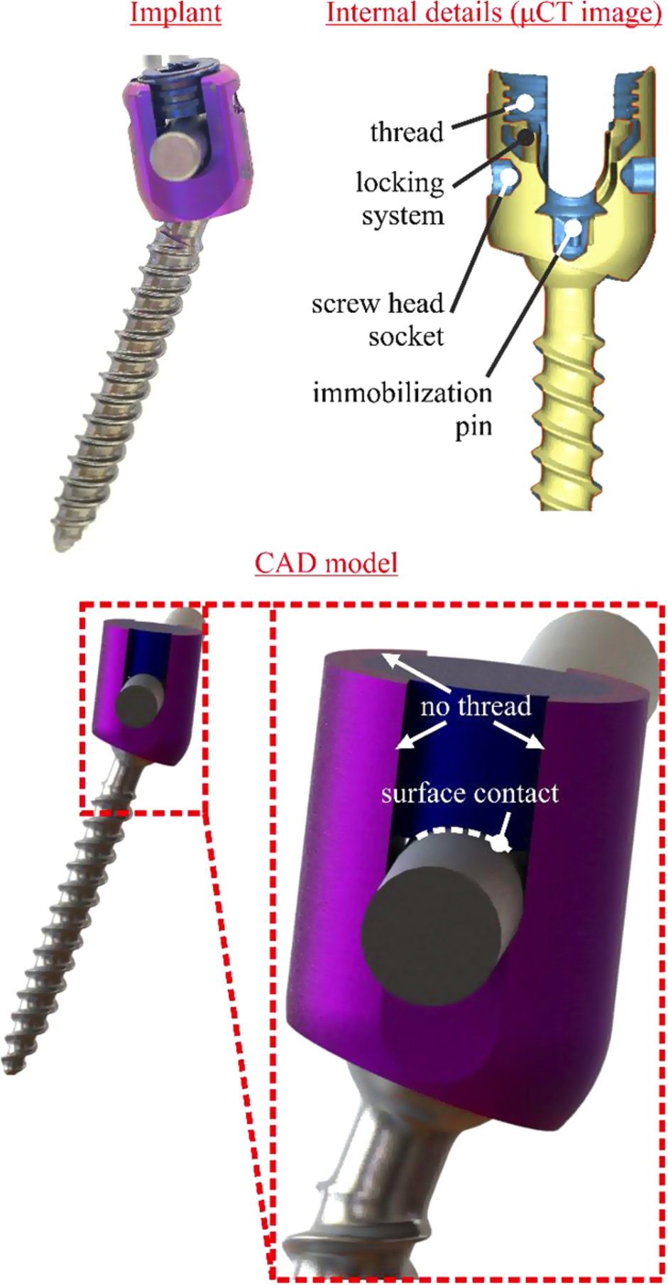
Physical vs. reverse engineered implant geometry (model simplifications). (Colors are visible in the online version of the article;
Each screw was embedded in a cubic geometry imitating vertebral bone. This geometry consisted of three compartments, the first one considering material properties of pedicle, the second one cancellous and the latter one cortical bone. This consideration is important as the pedicles have been reported to carry up to 80% of the load induces by spinal fusion devices [12]. The part of the geometry imitating pedicle bone covered 17.8 mm of the pedicle screw [13], the anterior cortical shell was considered to be 1 mm thick [14] and the interposing volume reflected the trabecular structure of the vertebra [15]. The first implantation scenario considered the pedicle screw to be embedded 42 mm deep into the bone matter whereas 10 mm of the screw’s body length were revealed during shallow insertion. In either case, the pedicle screw spanned over the cancellous bone part into the anterior cortical shell, thus the bone cube hosting the screw was shortened in the latter implantation scenario. This approach was chosen as pedicle bone and anterior cortical shell (first and third bone compartment) are the main contributors to the implant’s anchorage and were therefore considered to maintain a constant length throughout both implantation depth scenarios. This hypothesis was considered critical, as the aim of the study was to evaluate the impact of the anterior–posterior sift of the stabilization and not its load distributing capacity among bone types.
During the simulation, the inferior support was always restricted of any movement and the load applied to the upper body. The response of the system was examined for two typical loading scenarios [16,17]. The first one consisted of a 50 N compressive load, which was applied on the upper fixation device, whereas a second loading scenario examined the biomechanical response of the system to 10 Nm torsion. The centre of rotation was assumed at the intersection of a theoretical line between the dorsal and ventral borders of vertebral body and the widest distance between the lateral borders of the vertebral body. This resulted in an offset of the torque application point, which was considered as a remote load at the upper body of the fixation device. Based on morphological characteristics of the spine available in literature [18], the torque was applied at a 14 mm offset to the sagittal plane, 15 mm one to coronal plane and 12.5 mm to the transverse plane of the outmost implantation point of the upper transpedicle screw (see Fig. 2).
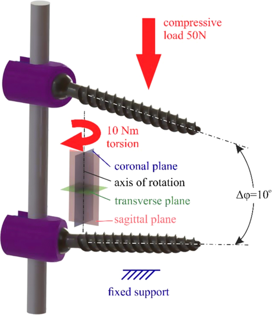
Load magnitude/direction (compression and torsion), boundary condition and relative implantation angle of the pedicle screws considered during the modelled scenarios. (Colors are visible in the online version of the article;
Determining the bio-realisticity of a numerical analysis is of vital importance when assessing the clinical perspective of a trauma. The verification of a FE model is fundamental aspect of the analysis [20], as erroneous predictions may yield catastrophic complications.
The verification of the theoretical model was achieved through the generation of a mesh independent FE grid [21]. Convergence studies, conducted separately on every model entity (pedicle screw, rod etc.), indicated the optimum element density in terms of computational efficiency and results accuracy. To avoid element shear locking and hourglassing phenomena during the analysis, second order reduced integration elements were employed throughout the model.
Model validation
There exists a consensus throughout literature that inter-patient variability is a significant limitation of medical FE models. The model was therefore validated against trend values which were experimentally determined. Two pedicle screws were embedded in two PMMA cubes and held together through a Ti rod, imitating a complete (unilateral) fixation assembly. The FE model was then evaluated against several uniaxial compression scenarios within the elastic response of the system.
The hierarchy of this validation process emphasizes on the ability of the model to simulate benchmark scenarios [22] fitting the purpose of this study. Based on the foregoing procedure, the developed model is accepted to provide an adequate degree of confidence for a comparative evaluation of the procedure variables involved in spinal fusion.
Results
The implantation of the pedicle screws at a 10° relative angle, lead to a stress decrease of approximately 10% for the Ti rod compressive scenarios, as illustrated in Fig. 3(a). The use however of PEEK rods significantly increases the mobility of the construct thus changing the loading angle of the pedicle screws which induces a stress increase of up to 15%.
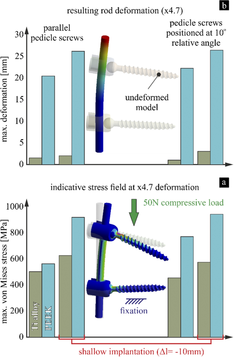
(a) Max. von Mises stress developing on the transpedicle screws and (b) resulting mobility of the system, for all compressive scenarios (implantation depth/angle and rod material dependent). (Colors are visible in the online version of the article;
The compressive stiffness of the fixation system predominantly depended on the rod material, with the implantation angle having a negligible and the implantation depth a marginable effect on the calculated deformation (see Fig. 3(b)).
During the application of torsion, the bone–implant interface exhibited notably lower stress values for shallow implantation. This was more pronounced in parallel embedded implants, with the PEEK rods favouring peri-implant stress concentrations, as observed in Fig. 4(a). The range of motion increased drastically for all PEEK based immobilization scenarios in particular for shallow embedded implants where the rotation of the system increased by up to 390%, as shown in Fig. 4(b). This was less pronounced during the use of Ti rods where the stiffness of the system was slightly higher for inclined screw positioning, but comparable for shallow and deep implantation.
There exists a consensus in literature that the anchorage of pedicle screws strongly depends on their implantation depth [23] and thus loosening is favoured by partially embedded screws. Clinical practice also suggests that optimum anchorage is achieved if the implant spams through the vertebral body into its anterior cortical shell [24]. This has lead physicians to assembly spinal fusion constructs as close to the vertebral column as possible.
A similar tendency was observed in this study, as the results indicate that implantation should always be performed as deep as possible in patients with healthy Bone Mineral Density (BMD) values. In these cases the choice of rod material entirely depends on desired rigidity of the immobilized segment. It should however be noted that the use of Ti rods restricts the mobility of the fused segment, while being able to carry a significant portion of the load the instrumented level is subjected to.
The investigation, provided refined insight for spinal fusion of osteoporotic patients, as the decreased BMD would render individual bone struts susceptible to fracture at lower stress values than in healthy patients. Therefore shallow implantation might be preferable in osteoporotic patients as the reduced stress concentrations in the bone–implant interface could contribute towards the long term stability of the implant. This effect was observed for parallel and inclined screw positioning, with the rod stiffness having a pronounced effect on the mobility of the system. This is expected to drastically affect the intradiscal pressure within the immobilized segment and therefore inclined positioned implants, connected with PEEK rods, could result in hyper-physiological loading of a degenerated disc, potentially further disturbing the balance of a pathological disc’s matrix under prolonged exposure. This should however be taken into account while considering clinical practice, suggesting that a longer pedicle screw could provide both, proper anchorage and stress relief in the bone–implant interface.
The considerable variations observed in the flexibility of stabilization devices, utilizing different rod materials, suggest that a rigid fixation (e.g. Ti rods) should be used for fusion of a spine segment whereas motion-sparing stabilization is preferable for non-fusion applications [8].

(a) Max. von Mises stress developing on the vertebral bone and (b) resulting rotational mobility of the system, for all torsional scenarios (implantation depth/angle and rod material dependent). (Colors are visible in the online version of the article;
Footnotes
Acknowledgements
The author would like to acknowledge that this investigation was funded by the General Secretariat for Research and Technology of Greece under grant agreement PE8(3227) and thank BETA CAE Systems SA for providing him with the CAE pre-processor ANSA, used during surface and volume meshing of the model.