
Abstract
The wear of the bearing surfaces of total disc replacement (TDR) is a key problem leads to reduction in the lifetime of the prosthesis and it mainly occurs due to the range of clearances of the articulating surface between the superior plate and core. The objective of this paper is to estimate the wear using finite element concepts considering the different radial clearances between the articulating surfaces of ceramic on ceramic type Lumbar Total Disc Replacement (LTDR). The finite element (FE) model was subjected to wear testing protocols according to loading profile of International Standards Organization (ISO) 18192 standards through 10 million cycles. The radial clearance value of 0.05 mm showed less volumetric wear when compared with other radial clearance values. Hence, low radial clearance values are suitable for LTDR to minimize the wear.
Introduction
Degenerative disc disease (DDD) is the gradual deterioration of the disc causing loss of its functions which leads to pain [1]. The most common surgical procedure is spinal fusion and the motion of the joint is drastically reduced [2,3]. However, in recent years, Total disc replacement (TDR) has been introduced to improve upon spinal fusion by restoring the motion [4]. There are different designs of LTDR devices, but most common one is ball-and-socket combination (ProDisc-L and Maverick), with a metal-on-polymer [MOP] or metal-on-metal [MOM] bearing surface. Ceramic on Ceramic [COC] is relatively a new design [5] used instead of MOP and MOM due to its excellent biocompatibility, wear resistance, corrosion resistance and strength [6]. In COC, alumina and zirconia are the two major types used in orthopedic applications.
Over a long period of usage, all implantable mechanical devices exhibits wear [5]. Relative motion under load at the articulating surfaces cause wear in implants [7]. This could induce the inflammatory reaction, can result in loosening of an implant and may lead to pain [8]. Experimental wear study on MOM lumbar disc conducted by Lee et al. [4] showed that the wear rate of MOM bearing surfaces is less than MOP combinations. The wear rate can be minimized when COC material combination is used for TDR [9].
Wear debris evaluations for TDR devices are done in wear simulators using the currently published ASTM/ISO loading profiles. However, it was too complex, expensive and difficult to conduct. FE models based on Archard’s wear formulation is an alternative method that can also be used for wear assessment of TDR implants. This formulation has been used by several authors for THR, TKR and TDR implants for the last decade [10–13]. The radial clearance between the articulating surfaces can vary the contact pressure and may affect the wear. Radial clearance was one of the important parameter to assess the wear and the effect of radial clearance between the articulating surfaces of COC artificial discs was not investigated so for.
The aim of this study was to apply the finite element method to analyze how the different radial clearances influence the wear and contact pressure of LTDR device. Thus, the present study helps in selecting the suitable radial clearance which minimizes the wear. FE implanted model was subjected to loading and displacement parameter for wear testing as per ISO 18192 over 10 million cycles.
Methods and materials
Modeling of TDR implant
The three dimensional ProDisc-L (PDL) model was developed using Pro-E Wildfire 4.0 (PTC, Inc., USA) and dimensions were obtained from the previous work [10]. The PDL implant model includes a superior metallic endplate, a convex polyethylene (PE) core and an inferior metallic endplate. The present study involves COC disc design. Therefore, both endplates and polyethylene core was replaced with alumina (Al2O3). The core was fixed into the inferior endplate, creating the ball and socket joint that articulates the surface of superior endplate. The PDL model was simplified by eliminating endplates keel and spikes for further meshing and analysis. The radial clearance between the articulating bearing surfaces was considered as 0.05 mm, 0.1 mm, 0.2 mm and the 2D systematic representation of radial clearance between the articulating surfaces was shown in Fig. 1.
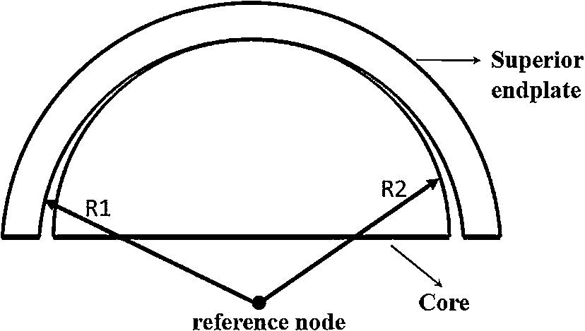
2D systematic diagram of radial clearance between the articulating surfaces. R1, radius of superior endplate bearing surface; R2, radius of polymer core bearing surface.
The solid PDL model was meshed with ANSYS. SOLID 187, a 10 node tetrahedral elements were applied to mesh the whole model as shown in Fig. 2. The number of elements within superior endplate, core and inferior endplate were respectively 7279, 15,108, 5067. The moving interface between the superior endplate and the core for implant model was simulated using ANSYS contact elements (CONTA 174 and TARGE 170) with standard contact behavior. The PE core base and inferior endplate upper surface was simulated using same contact element with bonded contact behavior. The contact algorithm used in this analysis was augmented Lagrangian method. The purpose of the augmentation was to reduce the sensitivity to contact stiffness. All things being equal, the augmented Lagrange method will produce less penetration than the pure penalty method. Initially, mesh convergence study was carried out by varying the number of elements to optimize the results. Young’s modulus and Poison’s ratio were obtained from [14] was utilized for the present work.

FE model of ProDisc-L. (Colors are visible in the online version of the article;
The base of the core was constrained with inferior endplate. Superior endplate was left unconstrained and could freely articulate on the convex surface of core, while inferior endplate was completely fixed at its base. A varying compressive load of 200 to 1750 N as per ISO 18192 [10] was applied through a coupled point on the superior surface of the superior endplate and it was shown in Fig. 3.

Phasing of the displacement and axial load curves for wear simulations as per ISO 18192 obtained from Rawlinson et al. [10].
Based on Archard’s wear theory [15] the wear rate can be predicted as follows:
The penetration of one component to another leads to linear wear (wear depth) and the formula for linear wear was modified from Eq. (1) as,
It is the volume of material removed from the articulating surface. Linear wear is converted into volumetric wear by multiplying it with the contact area of each instant. Therefore, the volumetric wear is given by,
After calculating the wear depth (linear wear) and the amount of material removed (volumetric wear) for first instance, the nodal positions were then updated to change in surface topography. One million cycle of wear was divided into 4 steps, with scaling of 250,000 times occurring at each step [10]. The FE model was simulated for 10 million cycles. The linear wear depth was computed as the average wear depth for the entire mesh. The total cumulative wear depth was calculated at the end of each million cycles.
Results and discussion
Contact pressure simulation
The contact pressure values were obtained from ANSYS for each gait instant upto 10 million cycles. The contact pressure distribution of COC material combination for 0.05 mm, 0.1 mm and 0.2 mm radial clearances were shown in Fig. 4. The contact pressure on core decreases, once the gait cycle starts increasing. The contact area increased with consequent cycles as the articulating surface of superior endplate became more conforming with core. Contact area was always concentrated around the pole and within the bearing surface of the core and extending circumferentially with increase in gait cycles. The maximum contact pressure was always at the outer periphery of the core during loading cycles as stated in Rawlinson et al. [10]. The contact pressure of a material combination depends mainly on its material property. Previous study on MOM combination by Wenzel and Shepherd [17] revealed that the contact pressure range in between 63–130 MPa. The present study involves COC material combination which had higher young’s modulus than MOM (Cobalt chromium alloy) couples. Hence, the contact pressure range 75.85–166.39 MPa was obtained which was quite higher than the MOM material combination. The relation between contact pressure distributions at the completion of 10 million cycles against the applied load for different radial clearances were shown in Fig. 5. The contact pressure values of 0.05 mm, 0.1 mm and 0.2 mm were 9.49 MPa, 15.81 MPa and 18.03 MPa respectively. The contact pressure values for 0.05 mm had been validated with the previous works and the validity of finite element simulation results was shown in [18]. The result showed that for increase in radial clearance which tends to increase the maximum contact pressure and this was due to the minimum conformal contact area for increasing radial clearance values.

Contact pressure distribution of COC material combination for different radial clearance at 50% gait cycle. (Colors are visible in the online version of the article;

Contact pressure distribution at the end of 10 million cycles for different radial clearances against applied load. (Colors are visible in the online version of the article;
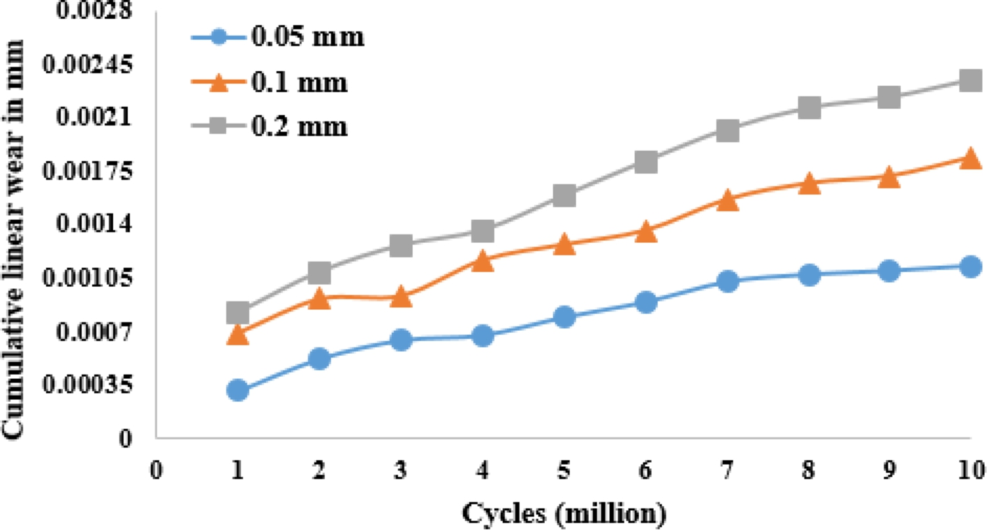
Cumulative linear wear for different radial clearance as a function of cycles (million). (Colors are visible in the online version of the article;

Cumulative volumetric wear for different radial clearance as a function of cycles (million). (Colors are visible in the online version of the article;
The linear wear predicted for 10 million cycles for different radial clearance values were shown in Fig. 6. At the end of 10 million cycles, the linear wear for 0.05 mm radial clearance was 0.0011 mm (validated with the results of [18]) which was quite larger when compared with MOM bearings which showed 0.0045 mm [5]. This was due to the wear coefficient of MOM bearing 1.01 × 10⁻¹¹ mm3/Nmm was much closer to COC combination. Linear wear increased 1.63 times when the clearance was increased from 0.05 mm to 0.1 mm and 1.27 times increased when the clearance was increased from 0.1 mm to 0.2 mm. It clearly showed that increase in radial clearance had a tendency to increase the wear depth. This was due to high contact pressure and less conformal contact area ultimately resulting in increase in linear wear.
Volumetric wear
The predicted volumetric wear for different radial clearance values up to 10 million cycles were shown in Fig. 7. At the end of 10 million cycles, the volumetric wear for 0.05 mm clearance was 0.113 mm3 (validated with the results of [18]) which was quite higher when compared with MOM combination as 0.275 mm3 [5]. The volumetric wear for 0.1 mm clearance was 0.118 mm3 and for 0.2 mm clearance was 0.13 mm3. The cumulative volumetric wear for different radial clearance values also remained almost constant through 10 million cycles. This reflects the same case as wear prediction of MOP done by Rawlinson et al. [10] but the cumulative volumetric wear at the end of 10 million cycles was 56.7 mm3 which was very much higher than the present result. It clearly showed that the volumetric wear for COC combination was lesser than other two combinations. Hence, low radial clearance value was most suitable to minimize the material removal due to the close conformity of the concave superior endplate surface against convex core surface.
Wear in the total disc replacement (TDR) was a significant clinical concern which reduces the lifetime of prosthesis. It induces the formation of potentially harmful debris and involves the risks of a new surgical operation. Wear was mainly caused due to the contact pressure between the superior plate and polymer core. So, minimizing the wear becomes very essential in biomedical applications. These proposed methodologies were similar to the previous works in hip prosthesis (THR) work which was validated with clinical problems. So, these results can be utilized for developing new design.
Conclusions
A three dimensional FE analysis was performed to predict the influence of different radial clearance over wear and contact pressure by considering the loading and displacement parameter for wear testing as per ISO 18192 over 10 million cycles. The result showed that the contact pressure increases with increase in radial clearance while the contact area decreases with increase in radial clearance. The cumulative linear wear increases for increase in radial clearance values once the gait cycle starts to increase. Smaller deviation found in volumetric wear for increase in radial clearance values. The predicted linear and volumetric wear was much closer to MOM combination and higher when compared to MOP combination. The radial clearance of 0.05 mm showed less volumetric wear among other radial clearance values. Therefore, COC type implant device with less radial clearance between the articulating surfaces was a superior choice to minimize the wear.