



Abstract
Total deformation and stability of straight and helical compression plates were studied by means of the finite element method (FEM) and in vitro biomechanical experiments. Fixations of transverse (TF) and oblique (45°) bone (OF) fractures have been analyzed on sheep tibias by designing the straight compression (SP) and Helical Compression Plate (HP) models. The effects of axial compression, bending and torsion loads on both plating systems were analyzed in terms of total displacements. Numerical models and experimental models suggested that under compression loadings, bone fracture gap closures for both fracture types were found to be in the favor of helical plate designs. The helical plate (HP) fixations provided maximum torsional resistance compared to the (SP) fixations. The fracture gap closure and stability of helical plate fixation for transverse fractures was determined to be higher than that found for the oblique fractures. The comparison of average compression stress, bending and torsion moments showed that the FEM and experimental results are in good agreement and such designs are likely to have a positive impact in future bone fracture fixation designs.
Introduction
Internal fixation devices in orthopedics have been in use for more than a century, but there is still need for new designs that will speed up the bone union without causing adverse effects in bone physiology. A number of compression plates are commonly used for bone fracture fixation, however, these still have some shortcomings and provide limited fixations [1,2]. Bone fractures were experimented under four-point bending and torsion tests and compared with the new minimum contact plate (MCP) [3]. The most common bone fractures are transverse and oblique fractures in long bones. Experimental analysis and comparison were made between straight and helical plates, however, the work was lacking of theoretical modeling [4]. The fixation of these fractures are reported to be causing loosening, bone necrosis, malunions and therefore it is a need to develop new alternative fracture-fixation assemblies [5–10]. The ideal fixation treatment of bone fractures has not been agreed upon yet [11] and consequently fractured bones are still treated by fixation techniques such as SP plating and intramedullary nailing. Conventional straight plating (SP) induces undue stress-shielding of the fractured bone and may cause some segment weakining and loosening problems. Another disadvantage of conventional plating is the lack of torque ability which makes it more difficult to gain satisfactory plate positions and may result in some degree of malrotation [12]. Because of such disadvantages of SP plating, helical plates could be applied orthogonally to long fractured bones. In some cases the cost of self-locking plates could be as much as four times higher than non-locking conventional plates. With helical plating, this disadvantage could be minimized. The production of helical plates is easy and inexpensive. Through an idealized finite element analysis, it was reported that the helical plating may also enable minimizing the fracture gap because the helical plate is fastened and wrapped around the fractured bone [11,13]. Fernandez [14] was the first surgeon to propose and discuss the helical plates as an alternative to SP plating used for fixation of the internal bone fractures. Clinical and experimental trials of helical plating are reported in [4,15,16]. The lateral distal type of helical plate was recently used to fix shoulder proximal and middle humorous fractures, At the end of twelve months, good clinical and functional results were reported [12]. However, no combined theoretical and experimental analysis was supported showing the advantages and disadvantages of such fixation models between the straight-SP and helical plating for oblique and transverse fractures.
In this study, a three dimensional elastic-plastic analysis was executed to show the advantages and disadvantages of SP and HP fixations using a finite element model. The models of helical plate fixations for oblique and transverse fractures were evaluated in comparison with conventional plate fixation under compression loads, bending and torsion moments. The analysis has been validated by axial compression, bending and torsion experiments. The location and distribution of displacements concentrated around screws or on plates at fracture-fixation zones were evaluated.
Materials and methods
Theoretical model was designed and the analysis has been validated throughout axial compression, 3PB loads and torsion moments. FEM analysis was carried out for fixation assembly groups of oblique bone fracture-straight plate, oblique fracture-helical plate (angled 90°); transverse fracture-straight plate and transverse fractures-helical plate by using the ANSYS 12.1. Figure 1 shows the meshing used during analysis for the helical and straight plate fixations. Bone was modeled as a transversely isotropic material and was utilized to represent the mid-diaphysis of the sheep tibia. Bone was considered as a hollow cylinder having an outer diameter of 17 mm, with inner diameter of 7 mm and a length of 200 mm (average measurements from the sheep tibia). The bones were fixed by plates having 6 screw holes. The FEM model is depicted using the material properties given in Table 1. Tetrahedron elements having minimum 0.00517 mm edge dimensions were used for the geometry of the bone-plate assembly. Meshing was preferred as “fine” along plate-bone contacts where at fracture gap and screw sites, however, it was preferred as coarse at remaining zones. In addition, remeshing was preferred at critical contacts such as plate-bone-screw and fracture gap. The total number of 114717 nodes and 63969 elements were used in each fixation model. The 65% of elements were used at critical zones such as bone fracture gap and plate-bone contacts and 35% were used for the remaining zones. A description of the anticipated contacts was expected to be defined by the program, and unidentified parts of the design were also introduced to the system manually. Seventeen contacts with eight surfaces were defined as the surface contacts which were identified as the targets. Plates and screws are defined as bonded to bone. To determine stress and strain, the model was run until failure of these fixations occurred. In the analysis, the initial fracture bone gap clearance was assumed to be 1 mm and the movement or dislosure of the gap was considered as unstable conditions for the fracture-fixation model.
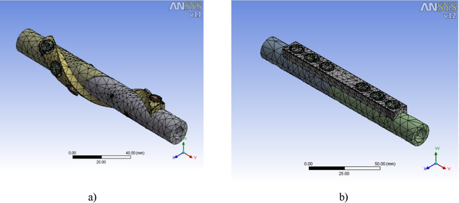
FEM meshing for, (a) Conventional-straight SP, (b) Helical SP model.
Mechanical and physical properties of materials used in FE analysis
Biomechanical tests were executed using a Universal Test Machine (SHIMADZU Autograph AG-X 50 kN Tokyo, Japan) and all data were recorded by an acquisition system. Plates and cortical screws used in this study were made of stainless steel (ASTM F138). The dimensions of the 6-hole plates were 110 mm in length, 13 mm in width and 4 mm in thickness. The dimensions of the screw holes were 5 × 9 mm and the distance between each hole was 6 mm from the ends. Freshly provided sheep tibias (from butchers) were divided into four groups (Groups 1 through 4) in a combination of fracture plate fixations (Table 2). Tibias in the first group having transverse fractures (TF) were fixed by conventional compression plates (SP). The second group consisted of tibias having 45° oblique fractures (OF) and were fixed by SP. Tibias in the third group having transverse fractures (TF) were fixed by helical plates (HP). Finally, tibias in the fourth group having oblique fractures (OF) were fixed by helical plates (HP) as tabulated in Table 2. These groups were all subjected to compression, bending and torsional tests. An average diameter was determined (as input into the test machine) by measuring 7 tibial shaft diameter, then the fractural stresses were calculated by dividing the fracture force to the that cross section of tibial shaft.
Fracture-fixation experimental groups
In order to determine and validate the stability of various fracture-fixation combinations used in this study, the biomechanical tests were conducted by applying axial compression, bending and torsion loads. Similar tests were conducted with respect to the fixation of straight and helical plates which were applied to longitudinal humeral fractures [15,16]. FEM analysis took place according to the fracture-fixation groups as represented in Table 2. The models were compared with those of the same experimental groups corresponding to TF-SP (Group 1), TF-HP (Group 2), OF-SP (Group 3) and OF-HP (Group 4). The fixation systems and displacements from their original gap position (1 mm initial clearance) behaved differently under different loadings. The preferences of these fracture fixation systems have been changed depending upon the various loading types. The effects of loading types on different fixation systems in particular sections are presented. The model was built according to two phenomenas; one is the screw displacements and another gap movement from its initial position. The system stability was evaluated by considering the gap clearance and closures. The comparisons were made between the straight plating (SP) and fracture (Transverse-TF and Oblique-OF) types, e.g. SP-TF and SP-OF as shown in Fig. 2(a) and (b). Other comparisons were made between the HP and fracture types, e.g. HP-TF and HP-OF (Fig. 3(a) and (b)).
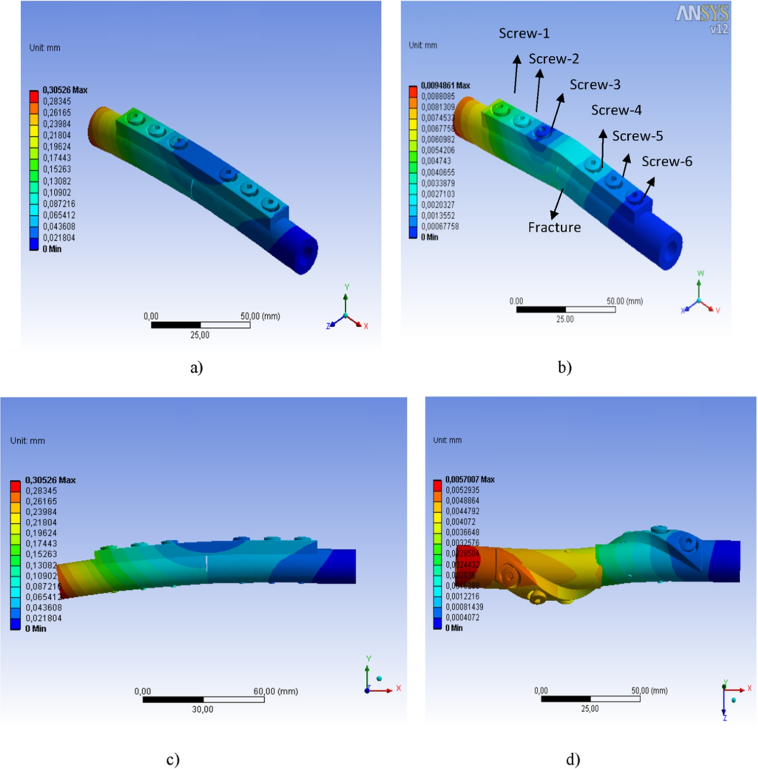
Conventional – straight SP fixation model for, (a) transverse (SP-TF) and (b) oblique fracture (SP-OF) under axial compression loads, (c) fracture-gap movements in straight plates at fracture site, (d) fracture-gap movements in helical plates at fracture site.

Helical plate fixation model for, (a) transverse (HP-TF) and (b) oblique fracture (HP-OF) under axial compression loads.
In both the transverse and oblique fractures, the maximum total displacements were found to be 0.30526 mm (Fig. 2(a)) and 0.0072 mm (Fig. 2(b)) respectively, as straight plate fixations were implemented. As shown in Fig. 3(a) and (b), as a result of the axial compression loads implemented on the fixation models, displacements occurred in bone and screw bonds for HP-TF and HP-OF models. The models had less displacement in the transverse fracture angle. Also the gap movements (displacement) for straight plates and helical plates were found to be 0.09 mm and 0.12 mm, respectively (Table 3). The displacements for oblique fractures in our models were found to be smaller which indicates better stability. Deformation occurred in transverse fractures TF-SP model and was excessive around screw bonds where high levels of displacement occurred. The total displacements seem to increase in oblique fracture-SP plate model (OF-SP) due to excessive deformation. Maximum displacement occurred in the 1st, 2nd and 3rd screw and such deformations took place because of shearing where occurred between the screws and the straight plate fixation.
In 3P-bending tests, the transverse and oblique fractures fixed by both SP and HP designs were subjected to bending loads up to 35 Nm bending moments. Models given in Fig. 4(a) and (b), SP-TF (a) and SP-OF (b), have both been analyzed by FEM and 3PB-experiments. The transverse and oblique fractures were fixed by a SP (a) and a HP model (b) and were tested using torsional moments. The moments applied to the fracture-fixation models were just enough to disturb the stability (15 Nm). Excessive moments were not considered in this study. The total deformations and displacements of transverse and oblique fracture models were revealed by applying a 15 Nm torsional moment for SP and HP models and are shown in Fig. 6(a) and (b). The SP fixations have been used for a transverse fracture (Fig. 6(a)) and for an oblique fracture (Fig. 6(b)), respectively. Figure 7 shows the helical plate fixation models for a transverse fracture (a) and an oblique fracture model (b) under applied torsional moments. Torsional moments were applied to the TF-HP model on the opposite side of the helical wrapping direction on bone surface, which is the most critical in terms of torsional resistance. The minimum, maximum and average stresses under axial compression, bending and torsion tests for both FEM analysis and experiments were plotted in between Figs 8 and 10, respectively and the related groups were tabulated in Table 2.
Total displacements and bone gap movement under axial, bending and torsional loadings

Conventional-straight SP fixation models for, (a) transverse (SP-TF) and (b) oblique fracture (SP-OF) under bending loads.
Axial compression loading
It is apparent that the total displacement values are very close for transverse and oblique fracture fixations when helical plates are used (Fig. 2(a) and (d)). The maximum total displacement was 0.0057 mm in the transverse fracture – oblique plate models (Group IV) while it was found as 1 × 10⁻³ mm in transverse fractures – helical plate models (Group III). These displacement (or gap movement) values shown in Fig. 3(a) and (b) become higher towards the edge of plates when axial compression loads are applied. The gap clearances was found to be 0.001 and 0.0057 mm for TF and OF, respectively in which the (OF) shows better stability due to higher closure.
In transverse fracture – helical plate (TF-HP) models (Group-III), minimal deformation or displacement occurred in screw-plate connections and the highest displacement values were obtained in the 1st, 2nd and 3rd screw bonds. It is noteworthy to mention that such TF-HP fixation model caused less deformation than the oblique fracture-helical plate (OF-HP) fixation (Group-IV). Small amounts of displacement occurred in helical plate fixation design system and so less movement was also observed under axial compression loading. The helical plate fixation design did not fail or deformed under axial compression loads and screw fixation zones kept their stabilities. However, the system was unable to prevent any minimal movement as the compression load was increased. When Figs 2(a) and (b) and 3(a) and (b) are considered together, it is seen that the helical plate fixations have the highest resistance to external compression loads (Fig. 3(a) and (b)).
When the straight-SP and HP models are compared to each other, the helical plate has the higher resistance to axial compression loads. The displacements from the original fixation position were also found to be maximum at the screw-bone connections of the conventional SP fixation. Especially the connections at screws 1, 2 and 3 were exposed to higher deformations than the rest of screws used for this fixation. In axial loading, since the gap angle in oblique fracture was taken as 45°, the lower gap movement or gap closure, however, higher screw displacements occurred (Fig. 2(a)). Maximum displacement obtained with helical plate systems occurred around the 1st screw which is was not deformed under the loads applied to the system and did not cause any damage to the bone (Table 3).
Three point bending (3PB) moments
SP-TF (Fig. 4(a)) and SP-OF (Fig. 4(b)) models were analysed with respect to total displacements. The maximum total displacement was found to be 1, 3 × 10⁻³ mm for SP-TF and the total displacements in SP-OF fixation models were 0.0045 mm. In a similar study, although only pull-out tests were conducted experimentally, Krishna [8] determined the gap movement (displacement) values as 0.02 mm and 0.3 mm for straight and helical (180°) plates, respectively. The gap clearance for TF-HP was found to be 0.01 and 0.012 for the OF-HP, whereas 0.001 mm and 0.005 mm (Table 3) were found for the SP-TF and SP-OF, respectively.
Compared to the model given in [8] and considering the compression, bending and torsional moments, our current models seem to resist better to bending forces. In SP-OF plate fixation models (Fig. 4(b)), deformation occurred and stresses have been absorbed mostly by plates and not by the screws. The maximum displacement was 1.1 × 10⁻³ mm at the screw connections. Although a great part of the fixation in HP-TF (Fig. 4(a)) seems to resist to external loads and deformations concentrated intensively around the transverse fracture zone for the HP-TF model (Fig. 4(b)).

Helical plate fixation model for, (a) transverse (HP-TF) and (b) oblique fracture (HP-OF) under bending loads.
As a result of the bending loads, some screws (arrowheads) as shown in Fig. 5(a) and (b) along with the plates, have also been exerted to high deformations. The models that were assembled using helical plates showed as much as 2% less deformation than the SP fixations. The total displacement was found to be 0.018 mm (Fig. 5(a)), and 0.0015 mm (Fig. 5(b)) for the helical plate fixation (HP) model. Figure 5(b) shows that the total displacements ocurred and concentrated around the screws (arrowhead), and no deformation around the fracture zone. Displacement for the straight plate fixations appear around the point where the model was subjected to the bending loads (Fig. 5(a)). In the helical plate fixation, the fracture area produced more total displacement around screw connection zones (Table 3). Assembling the helical plates with the transverse fracture (HP-TF) has prevented movement of the system better than SP where total displacements were higher at the 1st and 6th screws (Fig. 5(b)). The displacements appears to be higher in this model, however, the effective force has spreaded over the all screws and connection points. Therefore, the helical fixation model has resisted better to bending loads and kept its stability better than the SP model.

Conventional-straight SP fixation models for, (a) Transverse fracture (SP-TF) and (b) oblique fracture (SP-OF) model under torsional moments.
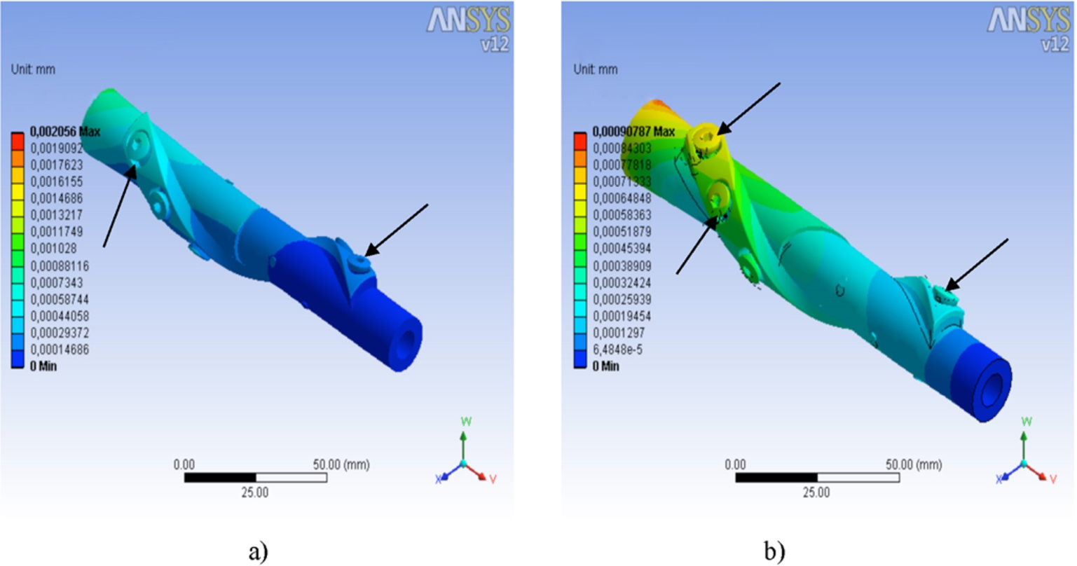
Helical plate fixation models for: (a) Transverse fracture (HP-TF) and (b) oblique fracture (HP-OF) model under torsional moments.
The plate-fracture models (SP and HP) were subjected to torsional moments (15 Nm). As shown in related figures, the total maximum displacement for transverse fracture is 1 × 10⁻³ (Fig. 6(a)) and 174.6 × 10⁻³ mm for oblique fracture (Fig. 6(b)). The torsional moments caused deformations particularly at the screws (arrowhead) for the oblique fracture (SP-OF) model and the deformations were lower in HP-TF (Fig. 7(a)) than the HP-OF model (Fig. 7(b)). It is emphasized that the (SP-TF) model (Fig. 6(a)) had lower strains producing less deformation and therefore preventing the stability of fracture fixation better than the (SP-OF) model shown in Fig. 6(b). Displacements appeared to have maximum values in the 1st, 2nd and 3rd screws under the torsional moment. It was observed that the screw connections in the straight plate fixation generally were unable to keep the stability of the fixation system. The gap closures of the helical plate (HP) fixations under torsional loadings were 0.0007 mm for TF and 0.0021 mm for OF, however for the straight plating (SP) for TF and OF were found to be 0.001 and 0.123 mm, respectively (Table 3).
In the HP-TF model (Fig. 7(a)), the deformation began from the screws and under a torsional moment, the maximum displacements occurred as 2.056 × 10⁻³ and 0.9 × 10⁻³ mm, respectively. In another study, under similar loadings, such values were found to be 8 × 10⁻² mm and 1 × 10⁻² mm respectively [13]. These displacement values, once again, suggest that our model provided better fixation than found in available literature. Stress values were also found to be concentrated on screws closer to the fracture zone than the screws fixed at points further away from the fracture zone [13]. As shown in Fig. 7(b), although the moments were applied in the most critical direction (opposite to the helical direction), no severe deformatin occurred and the model kept its stability. In helical plate models, the screw connections besides the torsional moment showed a maximum strain effect, but such effect was very low on the rigid side of system where the degree of torsion was zero. The torsional moment was applied on the helical plate fixation and had mostly been absorbed by the plates and screws. During the applied torsional moment, the total displacement and strains concentrated on the plate and screws, and most importantly away from the fracture area. It was shown that the system was not damaged and allowed the fracture zone to be minimally affected. Although the moments applied in the most critical direction, the gap movement in the HP model (fixation) appeared to be at minimal levels and protected the fracture zone better than SP model (Table 3).
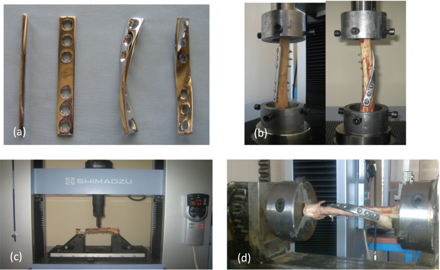
(a) Experimental straight and helical specimens, (b) test rig for Compression, (c) test rig for Bending, and (d) test rig for Torsion.
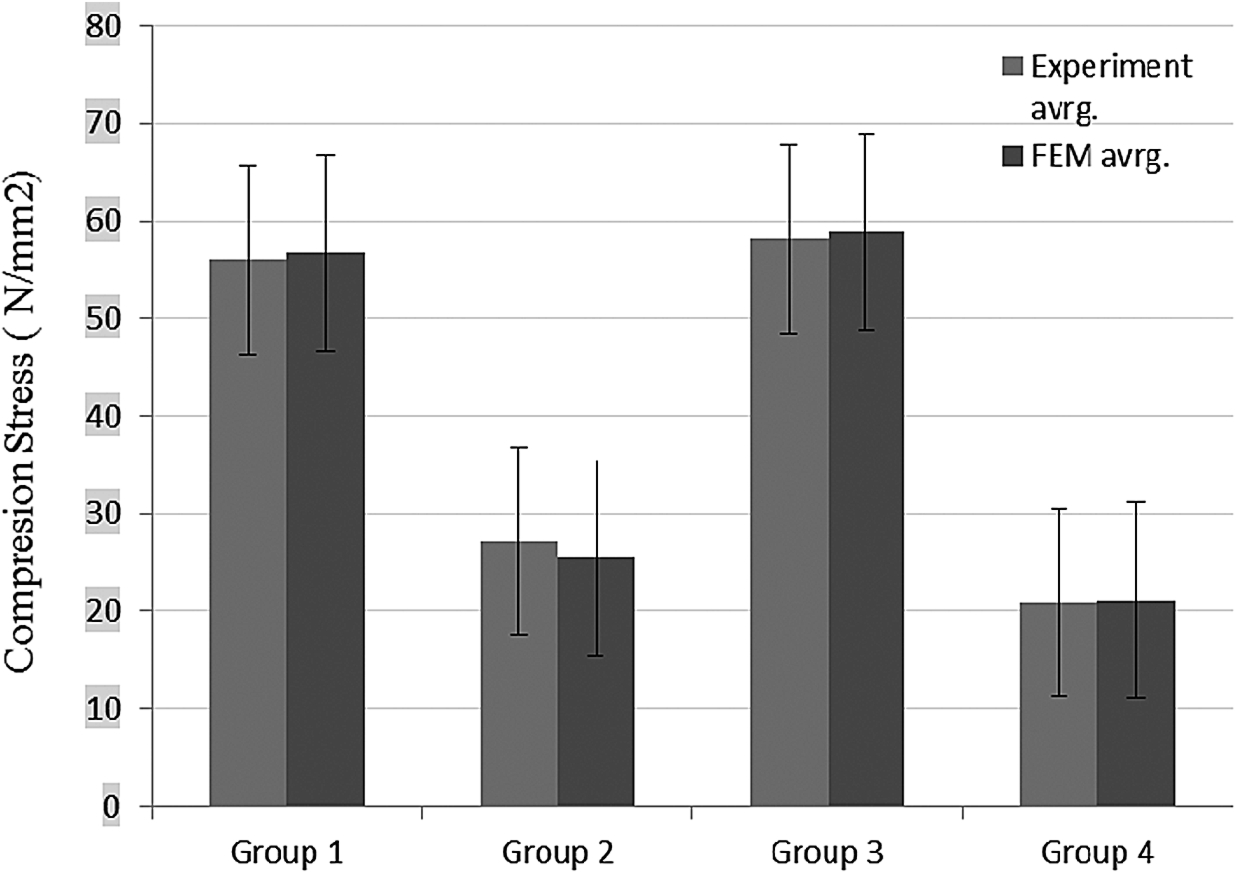
Average fracture stresses under axial compression loads, comparison with analytical (FEM) and experiments for all specimen groups.

Average bending moments of the specimen groups in comparison with FEM analysis and experiments.

Variation of average torsional moments with the specimen groups via FEM analysis and experiments.
Figure 8(a)–(d) illustrates the straight and helical compression plates, test rigs for compression, bending and torsional loads. The average stresses under axial compression, bending and torsion tests for both FEM analysis and experiments were plotted in between Figs 9 and 11, respectively. Figure 9 shows a comparison between experiments and FEM for the compression loads, Fig. 10 for bending and Fig. 11 for torsional loadings. From the figures, by comparing each groups shown in Figs 9–11, it is seen that, FEM results are in agreement with experiments. Under axial compression loads, the fixation models behaved differently. TF-CP (Group-1) and TF-HP models showed the highest fracture stress compared to the models of OF-CP (Group-2) and OF-HP (Group-4). However, both the Group-3 and 4 have higher resistance to bending loads than the other groups (Fig. 9). The analysis suggest that, SP and HP fixation models should not be considered for transverse fractures under axial compression loadings. Due to lower bending moments, for both fracture types (transverse and oblique), the helical plate models should be preferred (Fig. 9). Significant comparisonal results are shown in Fig. 10. Such results suggest that the helical plate models (Groups 3 and 4) are more resistant to torsional moments than the conventional straight plate fixation models (Groups 1 and 2). These results suggest that the fractures occurred due to torsional moments, particularly oblique fractures, it is better to fix and treat it by using the helical plate fixation models.
In this study some advantages of helical plate fixations were presented through FE analysis and compared with in vitro biomechanical experiments. The current modeling and experimental analysis demonstrated the biomechanical advantages and disadvantages of helical-plate fixations over the SP straight-plate design/fixations for oblique (OF) and transverse bone fractures (TF). The fracture gap closure or the movement of the gap was small when helical plates used in axial compression tests and they were successful to protect the fracture zone. FEM analysis and related experiments showed that HP models provided better resistance to various loadings than the conventional-straight plates for transverse fractures (TF). However, in bending analysis, SP models demonstrated better resistance to bending loads due to providing lower gap closure, preserved better fixation stability than the HP in the oblique (OF) and (TF) fracture models under bending loads. Compared to compression and bending loadings, due to very low gap closures in both fracture types, the fixation systems in torsional loadings when using helical plating showed minimal failures and kept its stability much better than straight-SP plate models. In addition, the screw connections were not significantly deformed and displacements were found to be much less in the helical plating (HP) than the straight-plate (SP) fixations. It can be concluded that the biomechanical stability of helical plate fixations (HP) are better, especially under torsional and compression loading than the conventional straight plate (SP) fixations. It must be emphasized that more anatomic localization and in-vitro/in-vivo studies should be conducted together with combined loadings before the clinical helical plate applications to be utilized commercially.
Conflict of interest
The authors have no conflict of interest to report.