
Abstract
The selection of stent and balloon type is decisive in the stenting process. In the treatment of an eccentric plaque obstruction, a symmetric expansion from stent dilatation generates nonuniform stress distribution, which may aggravate fibrous cap prone to rupture. This paper developed a new stent design to treat eccentric plaque using structural transient dynamic analysis in ANSYS. A non-symmetric structural geometry of stent is generated to obtain reasonable stress distribution safe for the arterial layer surrounding the stent. To derive the novel structural geometry, a Sinusoidal stent type is modified by varying struts length and width, adding bridges, and varying curvature width of struts. An end ring of stent struts was also modified to eliminate dogboning phenomenon and to reduce the Ectropion angle. Two balloon types were used to deploy the stent, an ordinary cylindrical and offset balloon. Positive modification results were used to construct the final non-symmetric stent design, called an Asymmetric stent. Analyses of the deformation characteristics, changes in surface roughness and induced stresses within intact arterial layer were subsequently examined. Interaction between the stent and vessel wall was implemented by means of changes in surface roughness and stress distribution analyses. The Palmaz and the Sinusoidal stent were used for a comparative study. This study indicated that the Asymmetric stent types reduced the central radial recoiling and the dogboning phenomenon. In terms of changes in surface roughness and induced stresses, the Asymmetric stent has a comparable effect with that of the Sinusoidal stent. In addition, it could enhance the distribution of surface roughening as expanded by an offset balloon.
Introduction
Stents are an effective treatment for peripheral artery disease and the usage of finite element method [FEM] for its development is growing rapidly. Over 100 different types of stent structure and geometry designs are currently being marketed or are in evaluation [1]. Numerous studies have been performed associated with the development and evaluation of stent design using FEM, either by the absence of plaque and arterial layer or with the interaction of both. A study considering the interaction of plaque and arterial layer was first promoted by Teo et al. [2] and Auricchio et al. [3]. To identify vascular injury possibility, Chua et al. [4] and Cui et al. [5] analyzed the stress concentration area induced by slotted tube type of stent during interaction with the arterial layer. Subsequently Lally et al. found that there was strong proportional correlation between the stress concentration within the vessel wall and the restenosis rate [6]. These results was confirmed by Takashima et al. by suggesting that the distributed contact area might reduce neointimal hyperplasia induction [7]. Concerning balloon expansion, Gervaso et al. pointed out that the modelling technique of the balloon seems essential to estimate the level of injury [8]. To avoid some limitations caused by model simplification, Gijsen et al. [9], Zahedmanesh et al. [10] and Morlacchi et al. [11] built more realistic simulation of stent deployment in human coronary artery. A more advanced study with various material properties was carried out by Pericevic et al. that used three different plaque types; cellular, hypocellular and calcified [12]. However, these studies still employed unified layer assumption for both plaque and arterial. On the other hand, some studies separately observed the characteristics of the arterial layer under certain pressure loading without stent intervension [13–19].
Study on stent-plaque-vessel wall interaction using current multilayer material properties for both plaque and vessel wall is still limited. The first study on this area is conducted by Holzapfel et al., which successfully derived a scalar indicator for a better judgment of three different stent types for iliac artery treatment [20]. Concerning the effect of asymmetric plaque to radial stiffness of stent, Brand et al. performed a numerical simulation on an asymmetric artery stenosis using net-structure stents [21,22]. They reported that the damage factor of asymmetric stenosis is lower than that of an axisymmetric case. Using multilayer properties material suggested by Holzapfel et al., Conway et al. developed a computational test-bed and its associated atherosclerotic plaque to assess coronary stent implantation. They found that stent design did not have a major impact on lumen gain behavior but may have an influence on tissue damage, which was strongly dependent on the underlying constitutive model used [23,24]. Another study incorporated two balloon shape (rubber and folded balloon) and various hyperelastic arterial model. Results indicated that a folded balloon is better than the rubber balloon and the blood vessel should be modelled as a multilayer structure with anisotropic hyperelastic behavior [25]. Nevertheless, none of the after-mentioned studies observed the effect of plaque eccentricity on the design of stent geometry. Almost all previous studies employed an assumption that either symmetric stent geometry or symmetric expansion would be enough to treat all shape of stenosed artery. In fact, applying symmetric stent geometry to eccentric stenotic plaque generates nonuniform stress distribution within the vessel wall which lead to in-stent restenosis [26–29] and also cause plaque prone to rupture [30–32]. Furthermore, many experimental studies confirmed that the mechanical behavior of an atherosclerotic plaque composition and healthy intimal layer is dissimilar, which also lead to the differences of its rupture criteria [33–37]. On the other hand, tensile tests carried out by Murphy et al. on electropolished 316L stainless steel stent struts revealed that a size effect, i.e. lower yield stresses, ultimate tensile strengths and failure strains, existed when the strut width was less than 500 μm [38]. Donnelly et al. also confirmed this and reported that a size effect existed in the form of a reduced fatigue endurance limit in 50 μm specimens [39]. Therefore, redesigning stent using updated mechanical properties and behavior, either of stent material or of the surrounding arterial layer, is required. This paper conducts development of new stent design to adapt eccentric plaque obstruction using finite element modelling.
Method
Finite element model
In order to develop new stent design, ANSYS R15.0 (ANSYS Inc., Pennsylvania, USA) was used as a simulation tool and CREO 2.0 (PTC Inc., Needham, USA) as a solid model builder. A stent model is made in CREO 2.0 due to its complexity, while models of balloon and stenosis carotid artery are directly built in ANSYS. A Palmaz and a Sinusoidal stent type is chosen for an ordinary stent model because these stents represent rigid and flexible structure of a slotted-tube stent [40]. An offset and a cylindrical balloon type is used to expand the stents. The geometry comparison between the offset and the cylindrical balloon type are shown in Fig. 1(a)–1(b). The geometry of the Palmaz stent, and the Sinusoidal stent and modification techniques are displayed in Fig. 1(c)–1(e), respectively. To inflate the stents, there are four expansion techniques used: (i) an ordinary stent expanded by an asymmetric type (offset) balloon, (ii) an Asymmetric stent type expanded by an ordinary cylindrical balloon, (iii) an ordinary stent expanded by an ordinary cylindrical balloon, and (iv) an Asymmetric stent expanded by an offset balloon. Combination of these expansion techniques in the FEM simulation will give a better understanding of the stent deployment.

Balloons and stents type used in simulation: (a) Offset balloon, a high-pressure balloon in the medical device industry, which has expandable and non-expandable parts [41]. (b) Ordinary cylindrical balloon, a non-folded balloon type that is used to simplify finite element procedure and to obtain a more proportional comparison with offset balloons. (c) Front and side views of the Palmaz, (d) Front and side views of Sinusoidal stent, from which the non-symmetric stent design is derived. Units are in mm for both stents. Modification types conducted in simulation (e) Variation of sinusoidal stent modification. Varying struts length is achieved by incrementally increasing the length of each strut by 5% of the direction of stent expansion, while varying struts width is done by narrowing the width of each strut at the direction of stent expansion by 5% subtraction, but widening them at opposite direction by 5% addition. Adding bridges is inserting bridges with different total length for each strut row. Varying curvature width of struts is conducted by widening curvature width of each strut by 5% in stages opposite to the direction of stent expansion. (f) Modification to improve the Ectropion angle, by lengthening the end-struts and straitening its curvature area.
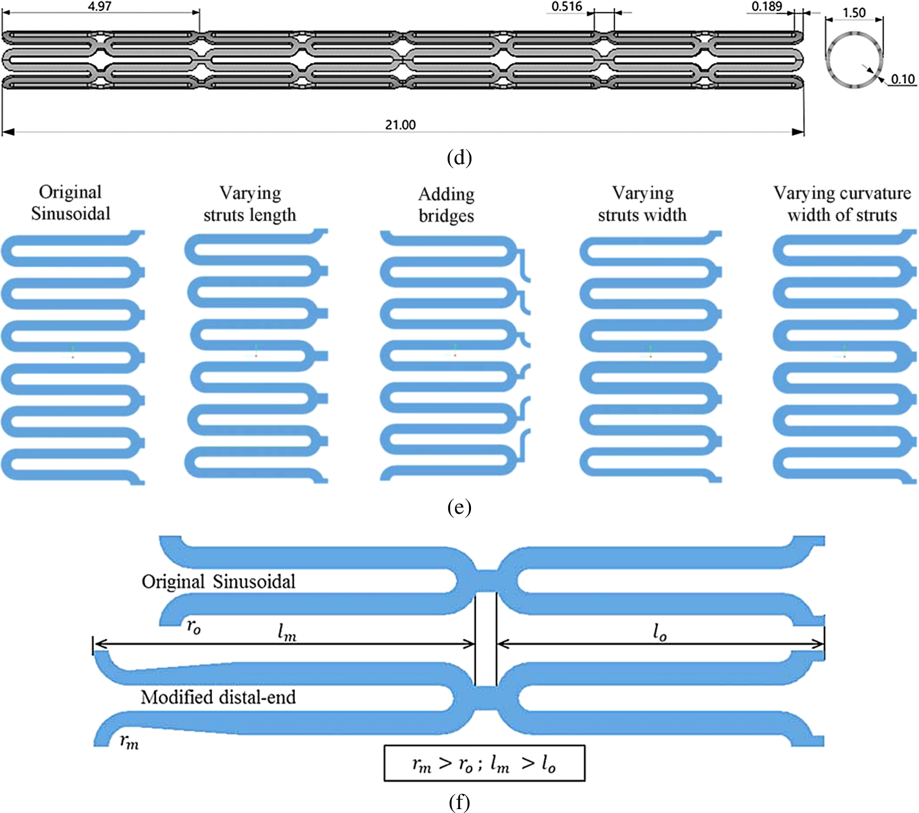
(Continued.)
The simulations consisted of three nonlinear dynamic transient analysis stages: i). Stent modification to built an asymmetric-expanded stent, ii). Changes of deformation characteristic during balloon expansion, and iii). Changes of stent surface roughness and stress distribution within an intact arterial layer (vessel wall). The modification of stent can be conducted utilizing FEM simulation. There are four modification made to enable asymmetric dilatation: varying struts length, varying struts width, adding bridges, and varying curvature width of struts. Design consideration principles underlying the modifications is referred to previous literatures. Modifying stent geometry is preferred rather than modifying the profile of stent surfaces, because it has more influence in term of increasing vessel wall stress concentrations, which leads to the rupture of internal elastic lamina and an exaggerated response to injury [42]. In the case of a stent that consists of same number of struts and slots, Chua et al. observed that increasing the length of the slots may be better than increasing the width of the slots as a higher expansion rate would be achieved [4]. One additional modification is required to reduce the Ectropion angle, which may be a cause of focal stresses on the vascular wall or the plaque [5]. This modification is conducted on the end-struts of the stent as illustrated in Fig. 1(f). To examine each effect of the modification, FEM simulation of a symmetrical ring model of one stent cell is generated in ANSYS. The simulation had no plaque and arterial layer interaction. This technique was also implemented by Dumoulin and Cochelin [43], Xia et al. [44] and Ju et al. [40]. The final design is obtained by combining positive modification results. Following the final design, analyses of the deformation characteristics, changes in surface roughness and induced stresses within arterial layer is carried out.
The effect of an asymmetric geometry on the changes of deformation characteristics is observed without intervention from the plaque and arterial layer. The deformation characteristic analysis investigated the effect of balloon expansion on each stent using a method proposed by Migliavacca et al. [45]. It consisted of five quantities, which is evaluated using following equations (Eqs (1a)–(1e)):
As the analysis of deformation characteristics completed, both analyses of the changes in surface roughness and the induced stresses are executed simultaneously. In these analyses, the stent should be inflated inside the plaque and the arterial layer. A carotid artery was chosen for these analyses. An ideal model for the carotid artery is derived from the human internal carotid artery (ICA), as implemented by Iannaccone et al. [28]. The ICA was developed as a symmetrical geometric model with a small curvature (
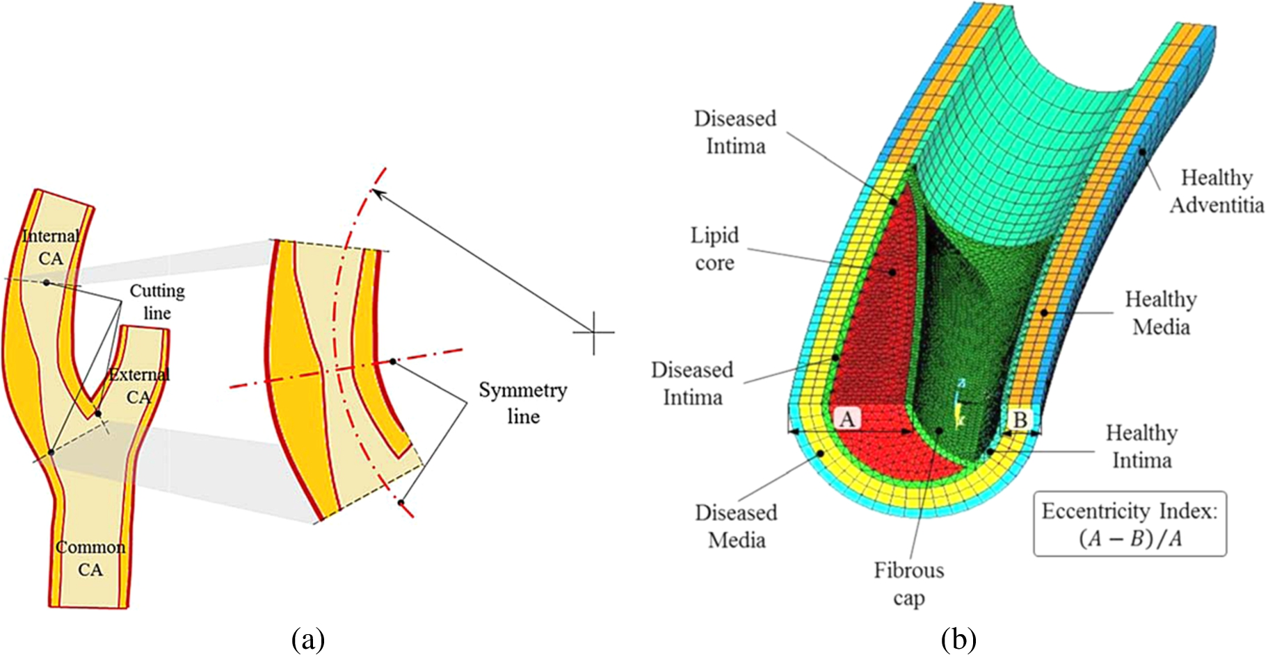
Axial section of the human carotid artery: (a) Applying cutting line to the internal carotid artery (ICA) model, then treating the cut model as symmetrical model with to reduce computational time. The internal carotid artery (ICA), where the stent is located, has 5 mm diameter in the cross section and of which 3.5 mm diameter was the lumen. An eccentric plaque obstruction with 1.8 mm thickness narrowed the lumen up to 1.7 mm in diameter. (b) One half 3D finite element model with detail layers for stenosed internal carotid artery.
For the analysis of stresses within arterial layer induced by the stent, Von Mises stress data is used, while the analysis of changes in stent surface roughness applied the formulation suggested by Syaifudin et al. It expressed the correlation between plastic deformation and 2D surface roughness of 316 stainless steel, which is stated as follows:
All the simulation used the material property of 316 stainless steel for the stent and polyethylene terephthalate for the balloon. Particularly for interaction with plaque and arterial layer, human carotid artery and human carotid plaque type fibroatheroma was used for the stenotic artery. Multilinear isotropic properties for stent are obtained by a fitting curve from a 316 stainless steel tensile test (Fig. 3(a)). The material models other than the stent were defined as isotropic hyperelastic (nearly incompressible) for the balloon, plaque, and arterial layer. The balloon used material properties defined by Chua et al. [49], both for the ordinary cylindrical balloon and the offset balloon. To conform material properties gained from previous literatures, two layers of healthy carotid artery are defined as healthy media-intima and healthy adventitia. As for the stenotic artery, the layers consist of a fibrous cap, a lipid core, an intimal layer, and a diseased media-adventitia. Fibrous cap and intimal layer in this case were assumed to have the same material properties. All material properties data used in the simulation are summarized in Table 1. The Hyperelastic curve fitting feature in ANSYS was utilized to derive all material parameters constants, as presented in Fig. 3(b).
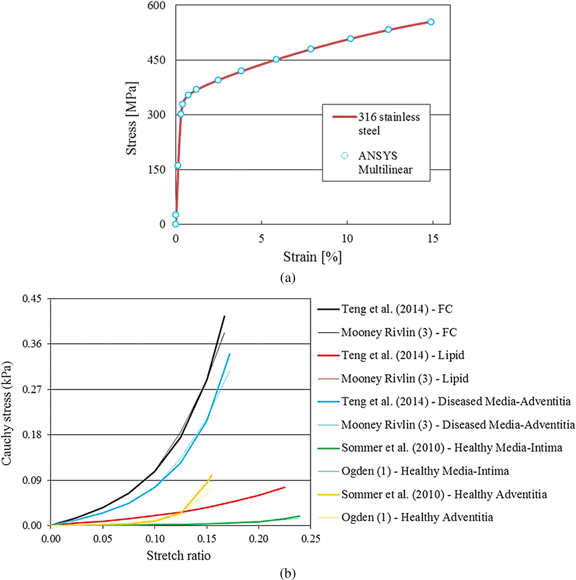
(a) Stress-strain relationship for 316 stainless steel obtained from the tensile test, featuring 14 point of curve fitting data for ANSYS simulation. The ordinate is stress value, in MPa and the abscissa is strain, in percentage. (b) Curve fitting result for fibrous cap, lipid core, diseased media-adventitia (a uniaxial tension test data by Teng et al. [35]), healthy intima-media and healthy adventitia (circumferential direction of biaxial tension test data provided by Sommer et al. [50]). The ordinate is Cauchy stress, in kPa and the abscissa is stretch ratio. All parameters have stable behavior for nonlinear simulation. From all parameters, there is a slight curve fitting deviation for healthy adventitia of CA. In this case, for the same value of high strain generated, lower stress value would be identified within the healthy adventitia of CA.
Material properties used in the FEM
Load steps were applied at the inner surface of balloon in the outward direction for all simulation models. Pressure loading for expansion process is set to 1.6 MPa for the ordinary balloon and 1.75 MPa for those of the offset, which is applied in 1 s. After reaching 130% of the nominal diameter of the stent, it was subsequently deflated for a half second to separate from the stent completely. For a comparison among the stents, starting time for balloon deflation was based on a similar nominal diameter of stent rather than on the magnitude of the inflating pressure. This balloon deflation strategy was recommended from previous studies comparing stents with different total surface area [27,51]. Different boundary conditions for the analyses were applied in the models, as depicted in Fig. 4.
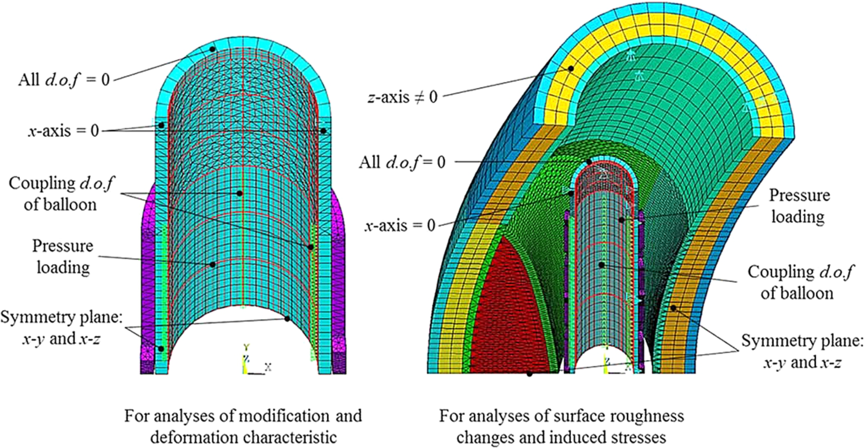
Boundary conditions for each analysis in polar coordinates: X, Y and Z are representatives of radial, circumferential and longitudinal directions, respectively. Coupling node to generate asymmetric expansion is represented by green triangle rows in the model. Pressure loading in the outward direction on the inner surface of balloon is represented by red lines.

Effect of modifications on the Sinusoidal stent struts is shown by composite bar chart (double ordinate axis). (a) Main axis (left ordinate) represents the distance between the struts, which is measured after the balloon removal, and the additional axis (right ordinate) represents the corresponding equivalent plastic strain. The inflated-side is the distance between struts which face to the direction of expansion, the fixed-side is vice versa, and the middle-side is the struts between them. (b) Side view of geometrical shape after asymmetric dilatation, with a unified legend of displacement provided below.
Modification analysis
Effect of modification on the Sinusoidal stent was evaluated by the distance between the struts, the distribution of equivalent plastic strain, and the geometrical shape after deformation. Fig. 5(a) shows the modification effect according to distance between struts and maximum equivalent plastic strain. For each modification, there are three colors on each column that represents the changes of struts distance. As the top row (green color) is larger than the bottom one (blue color), it denotes that the stent expands asymmetrically. The heights of the columns reveal nominal stent diameter after recoiling process. Fig. 5(a) indicated that not all types of modification succeeded significantly in inflating the stent asymmetrically. Varying struts width caused the largest asymmetric expansion by 1.83 mm of distance and also had the most minimal fixed-side by 0.41 mm of distance. Varying struts length had minimal effect on asymmetric expansion, it’s effects were almost equal to varying the curvature width of the struts. From the same bar chart, it was also inferred that the largest nominal diameter of stent is gained by adding bridges, because the distance summation of the inflated-side, the middle-side and the fixed-side could be assumed as half of the stent’s circumference. The maximum equivalent plastic strain of 0.2125 mm/mm was caused by varying struts width. The other changes in plastic strain were not significant due to the proportional difference between the inflated-side and the fixed-side. This tendency is understandable by verifying the result with Fig. 5(b). All type of modification, excluding changing the strut length, resulted in a change of the circumferential shape of the stent. The most regular shape was achieved by adding bridges. However, changing the width and the curvature width of struts should be applied with caution. Broadening a part of the struts may cause it to withstand stent expansion while another free modification part can expand freely, thus causing a strut to protrude out. Another important finding is that adding bridges in the stent structure could decrease balloon pressure needed for the expansion.

Modification effect on the end of stent struts, how large the reduction achieved is shown in left side and the amount of reduction is seen in the bar chart on the right.

Flat view of the final design of the Asymmetric stent, which is shown from the central part to the distal. The design of U bridge is chosen due to it is short length and enables symmetrical modeling in simulation.
Figure 6 demonstrates the effect of modification on the end of stent struts to reduce the Ectropion angle. It can be seen by the bar chart on the right side that lengthening the end-struts and straitening its curvature area are able to significantly decrease the degree of Ectropion angle by 49%. This modification is expected to improve stress distribution within the arterial layer surrounding the stent. The final design of the Asymmetric stent is shown in Fig. 7. It is a flat view of the offset stent featuring with several types of modification. The length of the struts was increased by 5% of the total strut length, for each strut cell from the fixed-side to the inflated-side. The width of struts decreased by 5% of the total strut width, for each strut cell from the fixed-side to the inflated-side. An U bridge type was added, which has the shortest arm on the fixed-side and incrementally longer toward the inflated-side, to support the asymmetric expansion of the struts. This model has a similar nominal diameter and total effective length with those of the Palmaz and the Sinusoidal stent.

The changes of deformation characteristic after balloon removal: (a) The Palmaz, (b) Sinusoidal stent, and (c) Asymmetric stent.
Figure 8 depicts the influence of stent geometry on the changes in deformation characteristics by comparing the ordinary cylindrical balloon with that of the offset balloon. It was revealed that the offset balloon affects the changes of both dogboning and distal radii recoil. The most significant effect of the offset balloon is the dogboning. The dogboning was reduced by 45.0% for the Palmaz stent, 43.3% for the Sinusoidal stent, and 41.8% for Asymmetric stent, respectively. This phenomenon is mainly caused by a combination between stent rigidity and pressure direction of the balloon. By applying an offset balloon, the circumferential pressure is non-uniform, which will lead to more plastic deformation on some struts section and less plastic deformation on the opposite section. As a result, it withstands the stents from producing larger dogboning effect. The more rigid the structure, the less dogboning effect it produced. As for the distal radii recoil, the Asymmetric stent expanded by the offset balloon had the largest reduction of 17.8%, while, for the foreshorthening of Asymmetric stent, the expansion by offset stent had the opposite tendency. The other parameters such as central radii and longtitudinal recoils showed little influence on changes in the deformation characteristics.
It can be also noticed from Fig. 8 that the longer the slot of the stent, the higher radial recoil occurred compared to those of the Palmaz and the Sinusoidal stent as Migliavacca et al. [45] suggested. The Asymmetric stent’s central radii recoil was reduced to around 20% when compared to the Palmaz and the Sinusoidal stent for both types of balloon expansion. This is an opposite phenomena to the distal radii recoil of the longer struts. This suggests that the Asymmetric stent has a more flexible geometry set against the Palmaz stent. Furthermore, the dogboning of the Asymmetric stent was reduced by more than 50% compared to the Sinusoidal stent. It can be also noted that the modification on the end stents is effective to recover the Ectropion angle. This is important because the remedy focal stresses on arterial layer is controlled by it [5,51].
It can be seen in Fig. 8(c) that the dogboning phenomenon leads to foreshorthening tendency in the case of the Asymmetric stent though improving dogboning has a priority compared with reducing the foreshorthening. Studies to reduce the dogboning phenomenon has been conducted by Auricchio et al. and Wang et al. To keep the uniformity of the stent expansion, Auricchio et al. added small distal struts. After the stent deployed, the small distal struts deformed larger than the other struts parts, which could aggravate surface roughening [3]. Meanwhile, Wang et al. used a broadened strut for the end ring of the stent [52]. Aforementioned modification analysis demonstrated that widening the strut caused difficulty in expansion whereas other parts still dilated normally. As suggested by Chua et al., when a stent consists of the same number of struts and slots, increasing the struts length may be better than increasing the struts width, because increasing the length of struts does not have a major impact on the stress distribution in a slotted tube stent [49]. Therefore, lengthening struts of end ring of the stent and narrowing the curvature is preferable.
(a) Distribution of surface roughening on the stent surfaces, with a unified legend provided below. Location of fixed-side is on the top of stents and that of inflated-side is vice versa. Maximum changes in surface roughness are pointed by red arrows and different distribution regions are clearly seen inside red rectangle. (b) Distribution of induced von Mises stresses within intact arterial layer, with a unified legend provided below. High concentration regions are bounded by red rectangle. The X, Y, Z coordinates represent the polar coordinate system for both figures, where the X-axis is the radial direction, the Y-axis the circumferential direction, and the Z-axis the axial direction.

(Continued.)
Figure 9(a) shows surface roughening distribution on the stents surfaces for each expansion combination. It is described clearly that the geometry structure of the Asymmetric stent shifted surface roughening distribution, particularly reduced it on the fixed-side of the Asymmetric stent, either using ordinary cylindrical or offset balloon. Figure 9(b) displays induced stresses within the vessel wall for each expansion combination. It can be seen that offset balloon utilization tended to reduce stress concentration area within the vessel wall, which is represented by the less stress concentration area within red rectangle line. It is also important to note that the highest stress regions are located at the vicinity of the shoulders of the plaque and are not affected by either types of balloon or stent. These results are consistent with the study of Li et al. [31] and Kiousis et al. [32]. However, this finding moderately contradicts to the study of Brand et al. [21,22], which utilized bi-layer arterial vessels. The associated maximal value of surface roughness changes and induced stresses are summarized in Table 2. Various combinations between stents and balloons types produced minor influence on all parameters observed. The Asymmetric stent produced slightly larger surface roughening compared to both the Palmaz and the Sinusoidal stents, by 0.01 μm. Moreover, it generated higher induced stresses than the Palmaz and the Sinusoidal stents, by 0.4 MPa and 30 kPa, respectively. Larger surface roughness changes is caused by uneven expansion between struts and bridges. In fact, the chosen connector type provided small influences to the expansion of stent thoroughly. Future investigation needed to find better connector type that has more adaptive movement. Meantime, higher induced stresses within vessel wall is experienced by the Asymmetric stent due to directional expansion of offset balloon. This unsatisfactory phenomenon can be complemented by directing the expansion to the healthier arterial layer of a vessel wall, whose higher elasticity. In combination with the offset balloon, the Asymmetric stent could enhance the distribution of changes in surface roughness, i.e. following the direction of offset balloon expansion. The offset balloon itself could reduce the induced von Mises stresses during expansion in all stent types by 4.13%.
Magnitude of changes in surface roughness and induced stresses
Magnitude of changes in surface roughness and induced stresses
An important finding from the analyses is that the changes of surface roughness for all stent type was still below 0.671 μm, a threshold for stainless steel on human vein endothelial cell to cause endothelial cell activation and inflammation [53]. Based on this threshold, the Asymmetric stent type in this study could be safely accommodated in the treatment as well as the Palmaz or the Sinusoidal stent.
FEM simulation on the development of the Asymmetric stent to treat eccentric plaque of carotid artery was performed in this paper. Analyses to clarify the effect of modifications were conducted and comparison of the changes in deformation characteristics and surface roughness were also carried out. As a result, the following conclusions were made:
From four implemented modification types, the struts length did not affect the change in the circumferential shape of the stent. The additional bridges generated better post-expansion circumferential shape of stent and also decreased the nominal pressure. The struts width and curvature width of struts should be applied carefully to avoid protruding struts.
Lengthening the end ring of stent struts and straitening its curvature area are effective to decrease in the degree of Ectropion angle. They also reduce the dogboning phenomenon.
The Asymmetric stent succeeded in reducing the central radii recoiling and the dogboning phenomenon by up to 20% and 50%, respectively. However, other parameters showed little influence on the changes in deformation characteristics. The offset balloon demonstrated significant effects on the dilatation of the Asymmetric stent, especially in reduction of the distal radii recoiling. The offset balloon also increase the foreshorthening.
All type of stent studied here are suitable for treatment because the changes in surface roughness remains small. The Asymmetric stent has a comparable effect with the Sinusoidal stent in terms of the changes in surface roughness and induced stresses. In combination with offset balloon, it could enhance the distribution of changes in surface roughness.
In the stent deployment, positioning the stent inside a blocked artery precisely or without any malapposition, becomes a very difficult task. Experience of a doctor or physician will greatly determine the outcomes of stenting process. Nevertheless, a controversial development of stent should be performed to overcome this problem. This study hypothezied that modified stent struts and bridges would influence its performance in treatment of eccentric plaques. The results showed how geometry modifications could influence performance of stent expansion.
In the development of novel stent, analysis on the interaction between the stent and arterial layer is a necessity. This paper, which adopted multilayer material properties and some latest experiment result, is a pilot study to design a new geometry of a stent. As a first step of the new stent design, a series of analyses focused on the geometry characteristics and stress distribution was conducted. Further investigation should be considered the rupture analysis on arterial layer using specific damage parameters for human carotid artery and human carotid plaque, as recommended by Hozapfel et al. [54].
FE model simplification in this study and isotropic behavior used for the plaque or arterial layer, gives room for improvement. One may argue that considering internal CA from carotid bifurcation as a symmetry model is presumptuous step in FEM. Using anisotropic behavior to analyze stress distribution may be considered more appropriate. The study of anisotropic model for stent-arterial layer interaction was conducted firstly by Holzapfel et al. in 2005. Afterwards, the necessity of anisotropic model in simulation of stent-arterial layer interaction is still a debate amongst researchers, because of its complexity in FEM application. On the other hand, even the anisotropic model of plaque or arterial layer is necessary, the results of simulation with the isotropic model remains able to be considered in accordance with the comparative study of Schmidt et al. [55]. Therefore, the authors believe that the method and the result of the simulation could be useful as representatives of the development of new stent design. Nevertheless, considering anisotropic behavior in the analysis of plaque rupture or vessel wall inflammation may be a better method to observe the actual performance of Asymmetric stent. Furthermore, the investigation associated with misdirection of Asymmetric stent expansion and its malapposition should be conducted soon in the future.
Footnotes
Acknowledgements
This research work is partially supported by JSPS Kakenhi (26420001) and The Amada Foundation. The authors acknowledge these supports.
Conflict of interest
There are no actual or potential conflicts of interest.