
Abstract
BACKGROUND:
Component malalignment in unicompartmental knee arthroplasty (UKA) has been related to the concentration in tibiofemoral joint of contact stress and to poor post-operative outcomes. Few studies investigated a biomechanical effect of femur component position in sagittal plane. The purpose of this study was to evaluate the biomechanical effect of the femoral components on the sagittal alignment under flexion and extension conditions using computational simulations.
METHODS:
The flexion and extension conditions of the femoral component were analyzed from 10° extension to 10° flexion in 1° increments. We considered the contact stresses in the polyethylene (PE) inserts and articular cartilage, and the force on the collateral ligament, under gait cycle conditions.
RESULTS:
The contact stress on the PE insert increased as flexion of the femoral component increased, but there was not a remarkable difference in the amount of increased contact stress upon extension. There was no difference in the contact stress on the articular cartilage upon extension of the femoral component, but it increased in flexion during stance and double support periods. The forces on the medial collateral ligaments increased with the extension and decreased with the flexion of the femoral component, whereas the forces on the lateral collateral ligaments showed opposite trends.
CONCLUSIONS:
Surgeons should be concerned with femoral component position on UKA not only in frontal plane but also in the sagittal plane, because flexion or extension of the femoral component may impact the PE or opposite compartment along with the surrounding ligaments around knee joint.
Introduction
Unicompartmental knee arthroplasty (UKA) has recently been recognized for the effective treatment of knee arthritis with excellent short- and long-term outcomes, with particular emphasis in the case of patients suffering from medial compartmental disease [1–4]. The survival rate of UKA is mainly dependent on the component position, and malalignment of the prosthesis may result in poor post-operative outcomes and progressive wear, leading to early revision surgery [6,7]. However, there has been an argument over the accuracy of the implantation of UKA.
It was concluded in a previous study that total knee arthroplasty (TKA) was more accurate in determining the component position and limb alignment [5]. Comparison is challenging to achieve because variations in UKA alignment do not, as in TKA, affect the limb alignment as whole [8]. It is a function of the thickness of the prosthesis relative to the excised bone. However, poor component position may influence the prosthetic durability [8]. Common errors for alignment in UKA include the varus or valgus alignments of the femoral or tibial components, variations in the posterior tibial slope, and flexion in the femoral component [9]. It has been argued that the orientation of the knee components should be within a certain range, and the biomechanical effect on the knee joint function is negligible [8,10].
Gulati et al. reported that malalignment in UKA using the minimally invasive approach affected the functional outcome, and they recommended acceptable ranges of alignment [9]. However, a long-term follow up is required for collection of sufficient clinical references, and it is impractical to use experimental measurements to directly evaluate the stress distribution in the opposite compartment. The biomechanical effect of the component alignment on the contact stress on ultra-high-molecular-weight-polyethylene (UHMWPE) inserts, articular cartilage and ligament forces, can be practically evaluated using finite element (FE) analyses [11]. Numerous FE analyses of UKA have been reported [12–17]. Most previous FE studies have focused on stresses and strains in the tibia, and on the contact stress on polyethylene (PE) inserts, which are presumably related to the coronal malalignments of the tibial component and the PE insert [12–17].
In conventional UKA, flexion and extension position of femoral component is decided by distal femoral cutting methods such as using intramedullary femoral guide or tibial cutting plane. In planning robot assisted UKA, it is recommended that the femoral component cover the distal condyle from posterior to anterior as well as best match with the native J-curve of native femur [18], which makes the femoral component more flexed compared to sagittal reference line. So we tried to find out if the femoral component position in sagittal plane would have an effect on PE insert, the opposite compartment or ligaments around knee in medial UKA. In conventional UKA, femur position in sagittal plane also could be different depending on the cutting method, but surgeons are usually not concerned about the femur component position in sagittal plane compare to those in coronal plane or tibial sagittal slope.
The purpose of this study was to investigate the biomechanical response of the sagittal femoral component malalignment on the surrounding structures under gait cycle conditions. In particular, the contact stress on the PE insert and on the opposite compartment, and the force on the collateral ligament, has been evaluated. Validated FE model was compared to a variety of other aligned configurations. We developed the FE models from a flexion of 10° to an extension of 10° at 1° unit increments. We hypothesized that increasing sagittal flexion of the femoral component will increase PE stress.
Materials and methods
We used a previously validated method and model that includes the following features [11,19–21]. An FE model of the lower extremities was developed using imaging data obtained from a healthy, mature male (37 years old) athlete with no prior history of knee injuries. The model includes the bony structures of the knee joint, including details of the soft tissues of the patellofemoral (PF) and tibiofemoral (TF) anatomy. A three dimensional (3D) nonlinear FE model of a normal knee joint was developed using data from computed tomography (CT) and magnetic resonance imaging (MRI) scans of a healthy 37 years old male subject. The CT and MRI models were developed with a slice thickness of 0.1 mm and 0.4 mm, respectively. The medical history of the subject did not reveal any musculoskeletal disorders or related diseases arising from a malalignment in the lower extremity, thereby indicating a healthy knee joint (Fig. 1).

FE model used in this study for (a) intact knee and (b) UKA.
The reconstructed CT and MRI models were combined with a positional alignment of each model using commercial software (Rapidform Version 2006; 3D Systems Korea Inc., Seoul, Republic of Korea) for modeling the bone structures as rigid bodies using four-node shell elements [22]. Additionally, the major ligaments were modeled using nonlinear and tension-only spring elements [23,24]. The ligament insertion points were determined with respect to the anatomy defined by MRI datasets of the subject and descriptions based on previous studies [25–27]. The cartilage and menisci were modeled as isotropic and transversely isotropic, respectively, with linear elastic material properties using eight-node hexahedral elements [20,22,28]. The interfaces between the cartilage and the bones were modeled as fully bonded. The contacts between the femoral cartilage and meniscus, the meniscus and tibial cartilage, and the femoral cartilage and tibial cartilage were modeled for both the medial and lateral sides, thereby resulting in six contact pairs [21]. Convergence was defined as a relative change >5% between two adjacent meshes. The average element size of the simulated cartilage and menisci was 0.8 mm.
A fixed-bearing UKA (Zimmer, Inc., Warsaw, IN, USA) was virtually implanted in the medial compartment of the developed normal knee model. The bone models were imported and appropriately positioned, trimmed and meshed with rigid elements using surgical techniques [29]. Based on the dimension of the femur and tibia, devices of sizes 6 and 5 were selected for the femoral and tibial components, respectively.
Twenty one models were considered in this study. A reference, “neutrally aligned model,” was defined according to the conventional surgical technique by insertion of the femoral and tibial components perpendicular to the mechanical axis. This model represents a balanced knee joint, as shown in Fig. 2. The other 20 models, in which the bone resection planes were changed, were defined based on the neutrally aligned model. Femoral components varied from a maximum flexion of 10° to a maximum extension of 10° at 1° unit increments in the sagittal plane.

Schematic of FE models with femoral component malalignment of flexion 10° and 5°, neutral, and extension 5° and 10°.
With respect to the implanted model, a 1 mm cement gap was simulated to exist between the component and bone. The PE insert was modeled as an elastoplastic material, whereas the femoral and tibial components and bone cement were modeled as linear elastic isotropic materials [13,30–32]. The materials of the femoral component, PE insert, tibial component and bone cement, corresponded to cobalt chromium alloy (CoCr), UHMWPE, titanium alloy (Ti6Al4V) and poly(methyl methacrylate) (PMMA), respectively. The material properties expressed in terms of the Young’s modulus and Poisson’s ratio were as follows: CoCr: E = 220 GPa and v = 0.3, UHMWPE: E = 685 MPa and v = 0.47, Ti6Al4V: E = 110 GPa and v = 0.3, and PMMA: E = 1,940 MPa and v = 0.4 [28,30,32]. For the UHMWPE, the yield strength, the ultimate 117 tensile stress, and the plastic strain, were 17 MPa, 33 MPa, and 0.32, respectively [30]. The femoral component was in contact with the PE insert. The coefficient of friction between the PE and metal was set to 0.04 [30].
The FE investigation included two types of loading conditions corresponding to the loads used in the experimental part of the study for the UKA model validation and model predictions for the gait cycle loading condition.
The intact model was validated in a previous study, and the UKA model was validated by comparing it to models constructed in previous experimental studies [11,19–21,33]. The validation of the UKA model was performed for the tibiofemoral flexion angles of 0°, 30°, 60° and 90°, by using passive flexion simulations. Additionally, anterior and posterior drawer loads of 134 N were applied separately to the tibia at the knee center in a manner similar to that adopted in a prior experimental study [33].
Gait cycle loading was applied as a second loading to allow comparison of the biomechanical effect of the sagittal femoral component with malalignment. The contact stresses on the PE insert, articular cartilage and force on the collateral ligaments were predicted using the model under gait cycle loading conditions (ISO 14,243) [34]. Computational analysis was performed with force controls for both the TF and PF joint motions with respect to the compressive load applied to the femoral component. A proportional-integral-derivative controller was incorporated into the computational model to allow for the control of the quadriceps in a manner similar to that in the previous experiment [35]. Furthermore, the anterior-posterior (AP) load and the internal external (IE) rotation were applied to the PE insert, and the varus-valgus rotation in the medial-lateral direction was controlled by the ankle joint followed by the force of the quadriceps attached to the patellar button [34–38]. The FE model was analyzed using the ABAQUS software (Version 6.11, Simulia, Providence, RI, USA).
Results
Validation of the UKA model
The UKA model was validated using the anteroposterior tibial translations in the anterior and posterior drawer tests at 134 N for 6.1 mm, 9.9 mm, 8.7 mm and 8.5 mm, and 5.8 mm, 4.3 mm, 3.8 mm and 4.9 mm, respectively, at 0°, 30°, 60° and 90°, of knee flexion in the UKA model (Fig. 3). These simulation results confirmed the results from a previous experimental study within the selected range of values for the anteroposterior drawer loadings [33].
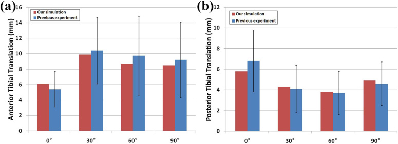
Anterior and posterior drawer tests in UKA model and previous experiments were compared in (a) anterior and (b) posterior translations.
Figure 4 shows the contact stress on the PE insert and articular cartilage under femoral component sagittal malalignment during gait cycle loading conditions. The contact stress on the PE insert increased during the stance phase, and decreased during the swing phase in the femoral component flexion model with malalignment, compared to the neutral position model (Table1). In the femoral component flexion model with 10° malalignment, the contact stress increased by 19% compared to the neutral position model.
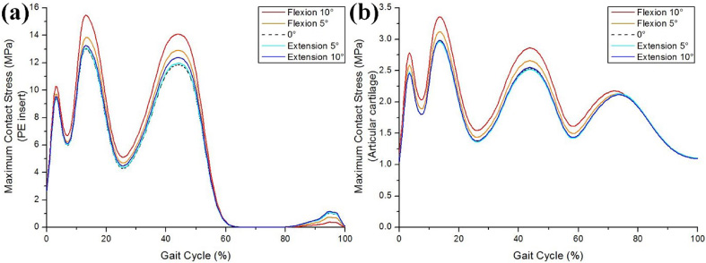
Comparison in the effect of femoral component malalignment on contact stress for (a) PE insert and (b) articular cartilage.
Increasing and decreasing rate of contact stress on the PE insert and articular cartilage compared with the neutral conditions during the stance and swing phase
In contrast, for the femoral component extension model with malalignment, there was relatively negligible contact stress on the PE insert up to 5°, compared to the neutral position model (Table1). From 6° and above, the difference in the contact stress became visible but it was less than 5%, even for 10° (Table1). However, the contact stress on the PE insert in the femoral component extension model with 10° malalignment increased by 11%, compared to the neutral position model during the swing phase.
There is nearly no difference in the contact stress on articular cartilage in the femoral component extension model from that elicited by the neutral position model during the entire gait cycle (Table1). However, the contact stress was greater in the femoral component flexion model with malalignment during the stance phase and double support periods, compared to the neutral position model, and there was no difference during the swing phase (Table1). In the femoral component flexion model with 10° malalignment, the contact stress increased by 13% compared to the neutral position model.
Figure 5 shows the ligament forces on the medial collateral ligament (MCL), lateral collateral ligament (LCL), popliteofibular ligament (PFL) and anterior lateral ligament (ALL), in the neutral position, and the femoral component sagittal malalignment models during the gait cycle condition. The force on the MCL increased in the femoral component with extension and decreased with flexion for models with malalignment, compared to the neutral position model. The force on the MCL in the femoral component extension and flexion models with 10° malalignment increased and decreased by 42% and 32%, respectively, compared to the neutral model. The opposite trends were found in the cases of LCL, PFL and ALL. The force on the LCL, PFL and ALL, decreased in the femoral component with extension and increased with flexion for models with malalignment, compared to the neutral position model. LCL and ALL were both influenced during the swing phase. In the femoral component flexion model with 10° malalignment, the forces on LCL and ALL increased by 21% and 17% compared to neutral position. PFL was influenced during the gait cycle, but the difference was not remarkable. The force on PFL increased by 7% in the femoral component flexion model with 10° malalignment, compared to the neutral position model.
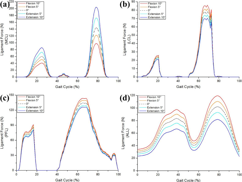
Comparison for the effect of femoral component malalignment in UKA model with respect to forces exerted on collateral ligament; (a) MCL, (b) LCL, (c) PFL and (d) ALL during gait cycle loading conditions.
The most important finding of this study was that the femoral component sagittal malalignment led to the biomechanical change in the knee joint, compared to the neutral position. Specifically, flexion malalignment of the femoral component should be avoided because it causes negative effects on both the PE insert and articular cartilage, as shown by the estimated contact stress. However, the appropriate extension malalignment of the femoral component could be encouraged. Care should be taken in robot assisted UKA especially, that even if it would be best fit to the distal femur in sagittal plane, too much flexion of femoral component would be greater contact stress on PE or surrounding ligaments. And surgeons may need to care about femur component position in sagittal plane in all UKA including conventional UKA, because sagittal femur position also could have an effect on PE insert, the opposite compartment and ligaments of the knee.
For TKA, a few degrees of component malalignment cause a significant abnormality in the leg alignment that increases the failure rate. In contrast, in UKA, the leg alignment depends on the component thickness rather than alignment. For the Oxford UKA (Biomet UK Ltd., Bridgend, UK), the thickness of the PE insert is selected to preserve ligament tension to normal levels, thereby restoring normal predisease alignment [9]. In the case of a fixed-bearing UKA, although the acceptable alignment range is broader than for TKA, it is not as broad as the case of the Oxford UKA. This is because there is a risk of edge loading and rapid wear with fixed bearing devices [9]. In contrast, the Oxford UKA has a spherical convex femoral component and a concave PE insert with a very broad contact area. Therefore, malalignment, even if it is quite substantial, does not lead to high contact stresses and rapid wear [39,40]. However, in general, poor positioning of the fixed bearing of the component may lead to early PE wear, poor functional results and a high-revision rate [6,7]. The manufacturers have developed new technology and prosthetic designs because of the importance of the implant positioning. For example, a single peg was changed to twin peg, and computer-assisted surgery, such as robotic and patient-specific-instrument surgeries, have been developed [41–43].
We evaluated the contact stress on the PE insert and the opposite compartment. The contact parameters have been discovered to be closely associated with the wear of the PE insert and with degenerative osteoarthritis (OA) in the opposite compartment of the knee joint [17,21,44].
We found that the contact stress on the PE insert and the opposite compartment increased with flexion malalignment of the femoral component, compared to the neutral position model. Such an increased contact stress could be found during the stance phase. In contrast, there was no difference in the contact stress on the opposite compartment, and slightly increased in the case of the PE insert in regard to the extension malalignment of the femoral component, compared to the neutral position model. The trend, whereby the contact stress on the PE insert increased with the extension malalignment of the femoral component, could be observed during the swing phase. Such a trend was caused by flexion and extension malalignment of the femoral component.
The contact edge loading was generated between the femoral component and the PE insert with flexion malalignment of the femoral component. However, it does not occur with extension malalignment. Because the contact areas between the femoral component and the PE insert in the coronal and sagittal planes do not change with extension malalignment of the femoral component, this led to lack of differences with the neutral position model between the femoral component and the PE insert in extension. In addition, the contact stress during the swing phase with flexion misaglinment of the femoral component decreased compared to the neutral position model because the contact surfaces were different during the swing and stance phases in the gait cycle for the knee joint.
The contact stress on the PE insert was always greater than that on the opposite compartment. This phenomenon could be explained by the difference in the stiffness between the PE insert and the articular cartilage of the knee with UKA. In the remaining compartments, the articular cartilages on both the tibia and femur displayed an elastic modulus of 15 MPa, while the PE insert exhibited an elastic modulus of 685 MPa. Consequently, there is a difference of more than one order of magnitude in the Young’s modulus between the medial and lateral compartments, and the materials in each compartment deform based on their elastic moduli [45]. In addition, the contact stress pattern in the neutral position model was well matched with that obtained in previous studies [30,46].
The opposite pattern was found for forces in the collateral ligament with flexion and extension malalignment of the femoral component. The force on the MCL increased with extension malalignment, while it decreased with flexion malalignment, in the femoral component compared to the neutral position model. There were opposite trends in the cases of LCL, PFL and ALL.
Smaller forces exerted on the collateral ligament corresponded to addressing a flexion tightness problem that also led to remarkable effects in extension. In addition, the increased force may cause ligament rupture. In other words, appropriate tension should be maintained. In general, ligament force is highly related to kinematics in knee joint. The posterior location of the knee joint contact point can, in principle, increase the quadriceps moment arm and reduce the collateral ligament force [47]. However, there has been no such a trend because the purpose of UKA is not to correct the malalignment of lower extremity.
Our results showed that sagittal alignment of the femoral component is an important factor to determine a biomechanical effect in UKA. Therefore, surgeons should be very careful in the decision making process for the sagittal alignment femoral component. It is important to reinforce the several strengths of this study. First, in contrast to previous UKA studies, the FE model in this study included the tibia, femur and related soft tissues [12–14]. Second, in contrast to the current biomechanical UKA model, the present study included the application of gait cycle loading, and not a simple vertical static loading condition [12,14,17,32,45]. Third, unlike previous studies, this study validated not only the initial FE model, but also achieved kinematic validation of the UKA FE models with experimental data [12,14,17].
Nevertheless, several limitations should also be noted. First, the FE model represented a fixed-bearing UKA, and the results should not be generalized to other implant designs, such as the mobile bearing UKA. As mentioned above, there could be no flexion and extension effects in the PE insert due to the spherical convex femoral component, and concave PE insert like the Oxford UKA. Second, the bony structures were modeled as rigid bodies. In reality, a bone consists of cortical and cancellous tissues. However, the purpose of the study was not the evaluation of the effects of different sagittal alignments for the femoral components at the bone. In addition, this assumption exerted a minimal influence on the study because the stiffness of the bone exceeds that of the relevant soft tissues [22]. Third, the computational model was developed using data from a single subject. However, this model does not emulate the in vivo environment since it does not consider anatomic variations and age-related changes in ligaments and cartilage. This approach is extensively used in orthopedic biomechanics [12–17,21,22,24,28,31,32,35,37,45,46,48]. However, the advantage of the computational simulation using a single subject is that it can determine the effects of component alignment within identical subjects with the exception of variables, such as weight, height, bony geometry, differences in ethnicities and sex, ligament properties and component size [48]. Fourth, only the gait cycle was simulated, and more demanding activities (such as sitting on a chair and standing, ascending and descending stairs, or squatting) would lead to more reliable results. Fifth, we assumed material properties and attachment points for the ligaments in the model based on literature values, though there is considerable variability in reported values. In addition, this assumption can affect the results. Fifth, we evaluated subject aged 37 years old. In general, knee arthroplasty is surgical treatment applied to older female patient. It might have caused morphology difference but we minimized the variation throughout validation of UKA model. Finally, we only studied on femoral component sagittal alignment. In future study, tibial component sagittal alignment and combination should be studied.
Conclusions
The contact stress on the PE insert and articular cartilage of the opposite compartment increased when the femoral component flexed in sagittal plane. Flexion and extension of the femoral component also showed an effect on medial and lateral collateral ligaments. Taking different operation methods of UKA could make a different position of femoral component in sagittal plane, surgeons may need to care about the femoral component flexion and extension, along with varus or valgus position in coronal plane or posterior slope of tibial component. Especially, too much flexion should be avoided because it may have an effect on the PE insert and the opposite compartment which may lead PE wear or progressive OA after UKA.
Conflict of interest
The authors declare no conflict of interest.