
Abstract
BACKGROUND:
Polymerization stress is a major problem in dental resin composite restorations. Two indentation fracture methods can be applied to evaluate the stress, however, they often calculate different values.
OBJECTIVE:
To compare polymerization stresses of dental composites determined by the two methods.
METHODS:
Glass disks with a central hole were used. Two indentation fracture methods (Methods 1 and 2) were employed to determine the polymerization stresses of low-shrinkage and bulk-fill composites. Method 1: Cracks were made in the glass surface at 300 μm from the hole. The hole was filled with the composite. Polymerization stresses at 30 min after filling were calculated from the lengths of crack extension. Method 2: The hole was filled with the composite. Cracks were introduced in the glass at 1,000 μm from the hole at 30 min after the polymerization and the stresses were calculated from the crack lengths. Stresses at composite-glass bonded interface were calculated from the stress values obtained by the two methods.
RESULTS:
The bulk-fill composite generated the smallest interfacial stress, and Method 1 revealed lower values than Method 2.
CONCLUSIONS:
The composites yielded relatively small stresses. Method 1 calculated smaller stress values, possibly affected by the lower threshold stress intensity factor.
Introduction
Resin composite is frequently used in daily practice for reconstructing tooth structure lost to dental caries and/or fractures, due to its improved esthetics and mechanical properties. Direct resin composite restorations are one of the major procedures for the current restorative dentistry. In spite of an increase in clinical applications of the direct resin composite restoration, a concern still remains due to its shrinkage during polymerization [1]. Through its polymerization process, carbon–carbon double bonds (C=C) in methacrylate monomers are converted to single bonds (C–C). The conversion causes the bond lengths to be shortened — resulting in volume reduction of methacrylate material [2]. As the resin composite shrinks in a tooth cavity in a condition of bonding to the surrounding tooth structures, force of the shrinkage generates stresses in the bonded tooth. The stresses are capable of inducing several undesirable phenomena such as deformation, fracture of the tooth and restorative, and delamination of the bonded interfaces [3]. In order to minimize the negative impacts of the stress, clinicians need to take major factors affecting the stress generation — properties of materials, polymerization procedures and placement techniques into consideration during the filling procedures of prepared cavities. Several manufacturers have developed dental resin composite materials exhibiting relatively low polymerization shrinkage naming them low-shrinkage or bulk-fill composites to prevent such post-operative problems.
When a pyramidal indenter is pressed into the surface of a brittle material, not only an indentation is formed but also radial cracks propagating from the indentation corners are made in the surface. Dimension of indentation generally expresses hardness of the material, and the indentation diagonal length and load are used for calculation of the hardness [4]. Softer materials yield longer diagonal length. Meanwhile, aspects of radial cracks express brittleness of the material — tougher materials exhibit shorter cracks [5,6]. Stress existing in the material also affects aspect of a crack. The propagation of crack tends to be arrested by compressive stress, while on the other hand is encouraged by tensile stress [7]. Utilizing behaviors of the cracks, several indentation fracture methods have been introduced to analyze the state of residual stresses in materials [8–10]. Most of such methods measure the existing stresses in the subjects — as indenting is done after stress generation. However, another method for measuring residual stresses has also been proposed [11] in which an indentation is made before stress generation. This method calculates stress from the length of crack extension. An advantage of this method is that localized tensile stresses can be repeatedly measured within the same specimen. Some studies have employed this method to evaluate the changes in polymerization stress of dental resin composites for several hours after polymerization [12,13].
The objective of this study was to compare the polymerization stresses of low-shrinkage/bulk-fill dental resin composites measured by two indentation fracture methods. The hypothesis tested was that stress values obtained with indentation fracture methods done before and after stress generation are similar.
Materials and methods
Preparation of glass disk
A soda-lime glass was selected to fabricate the molds for stress measurement for its sufficient adhesion to resin composites and possesses a similar elastic modulus of 70 GPa to that of human enamel [12]. Fracture toughness (K
c
) of the glass was measured by an indentation fracture method in a preliminary study. Vickers indenter was impressed into the glass at a force of 9.8 N for 15 s delivered by a microhardness tester (MVK-E, Akashi, Tokyo, Japan), and the toughness was calculated using the following equation [9]:
Thirty glass disks with a central cylindrical hole were fabricated (Yokohama Sekiei Co., Yokohama, Japan). The dimensions of disks were 12.0-mm in outer diameter, 3.0-mm in inner diameter and 2.0-mm in thickness. The top flat surface of the disks were polished to be less than 0.08 μm in R a . The disks were thermally treated at 510 °C for 24 h and slowly cooled in a furnace to release any residual stresses generated during the fabrication process [14].
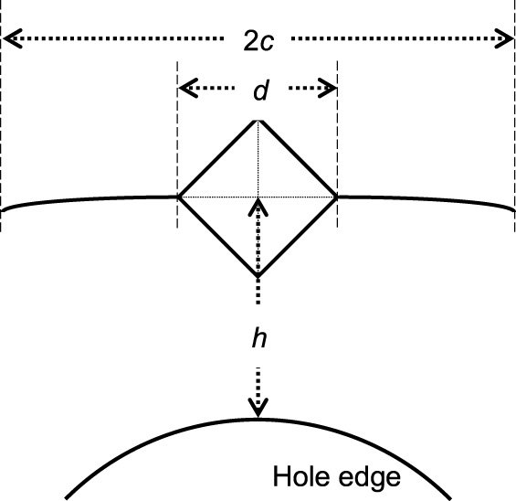
Site of Vickers indentation, and lengths of cracks (2c) and indentation diagonal (d) measured.
Indenting before stress generation (referred to as Method 1)
Fifteen disks were used in Method 1 (n = 5). To introduce initial cracks on the disk, a Vickers indentation was imprinted on the polished surface at a load of 9.8 N for 15 s using the microhardness tester. The indentation was positioned at a distance (h) of 300 μm from the edge of the cylindrical hole, and oriented so that an indentation diagonal ran along the hole edge. The indented disks were kept in a desiccator at a room temperature for a day to allow for slow crack growth by residual indentation stress [15]. The disks were observed to measure the lengths between the two ends of radial cracks (2c) running along the hole edge using a measuring microscope (STM-UM, Olympus Optical Co., Tokyo) at a magnification of 500× (Fig. 1). The indentations and cracks were covered with removable tape, and the inner surface of hole was adhesively treated by applying a mixture of a silane coupling agent (Clearfil Porcelain Bond Activator, lot No. 00255A, Kuraray Noritake Dental, Tokyo, Japan) and an adhesive primer (Clearfil SE Bond Primer, lot No. 00970A, Kuraray Noritake Dental, Tokyo, Japan). The mixture was gently air-blown for 5 s. The disks were fixed on a glass plate using a wax with a clear polyester film placed between the disk and plate. The hole was filled with one of the three light-cured dental resin composites (Table 1). The composite was covered with a clear film followed by irradiation for polymerization at 540 mW/cm2 for 45 s using a quartz-tungsten-halogen light unit (VIP, Bisco, Schaumburg, IL, USA). The tip of the light guide was kept in contact with the covering film during irradiation. The removable tape was removed immediately after irradiation, and the specimens were kept in the desiccator until the following measurement. Lengths of the cracks (2c
′
) were measured again at 30 min after irradiation. Stresses generated around the crack tips (𝜎
crack (300 μm)) were calculated using Eq. (2) [11 ].
After the measurement of 2c ′ , the specimens were observed at a magnification of 50× to verify the absence of interfacial debonding between the glass and composites.
Dental resin composites used for the stress measurement
UDMA: urethane dimethacrylate; TEGDMA: triethyleneglycol dimethacrylate; EBPADMA: ethoxylated bisphenol-A dimethacrylate.
Fifteen disks were used in Method 2 (n = 5). Removable tape was placed on a polished surface of the disk to prevent the silane primer covering the indentation site. The hole of the disk was silane-treated and filled with one of the resin composites as described previously. The removable tape was removed from the surface immediately after irradiating the composite at 540 mW/cm2 for 45 s. The specimens were kept in the desiccator for 30 min. A Vickers indentation was made at 9.8 N for 15 s in the surface at a distance of 3,500 μm from the outer edge of the disk, resulting in the distance (h) of 1,000 μm. The indentation site was defined with the distance from the outer edge as the exact location of hole edge could not be observed because the edge was covered by overfilled composite. The lengths of cracks (2c) and indentation diagonal (d) were measured within a time frame of 2 to 10 min after indenting using the microscope at a 500× magnification. Stresses generated around the crack tips (𝜎
crack (1,000 μm)) were calculated using Eq. (3) [9 ].
After the length measurement, the interfaces were confirmed to be intact at a 50× magnification. The surface of the specimen was ground to remove overfilled composite and to identify the location of hole edge using #1000 SiC paper. The distance (h) was microscopically re-measured for each indentation at a 500× magnification.
Stresses at the bonded interface (𝜎
interface
) were calculated from 𝜎
crack (300 μm) with Method 1 and 𝜎
crack (1,000 μm) with Method 2 using Eq. (4) [16,17]:
Crack lengths (c and c ′ ) and stresses around the crack tips (𝜎 crack )
Fracture of the glass disk was not observed with the three resin composite. Table 2 lists the lengths of cracks in Methods 1 and 2. In Method 1, mean length of the initial cracks (c) approximated 107 μm among the three groups. All the composites demonstrated extension of cracks, and namely tensile stresses were generated around the crack tips. No interfacial debonding was observed. The mean lengths of extension (c ′ − c) ranged from 0.9 (SDR) to 15.3 μm (Venus). In Method 2, the mean of crack lengths (c) ranged from 97.0 to 101.2 μm.
Means and standard deviations of c in Methods 1 and 2, c
′
and the lengths of crack extension (c
′
− c) in Method 1 (in μm)
Means and standard deviations of c in Methods 1 and 2, c ′ and the lengths of crack extension (c ′ − c) in Method 1 (in μm)
Table 3 exhibits the stresses around the crack tips (𝜎 crack ). Means of 𝜎 crack (300 μm) and 𝜎 crack (1,000 μm) ranged from 0.4 to 5.6 MPa and from 1.0 to 2.9 MPa, respectively. The smallest means were obtained with SDR in both methods.
Means and standard deviations of 𝜎 crack (300 μm) and 𝜎 crack (1,000 μm) (in MPa) with Methods 1 and 2, respectively
Stresses at the interface (𝜎 interface ) are listed in Table 4. Both factors (material and method) were statistically significant at p < 0.05. Tukey’s tests were performed among the pooled averages of each factor because the factorial interaction was not significant (p = 0.565). Values having the same alphabetical letter show no significant difference at p > 0.05. SDR generated significantly the smallest stress among the three resin composites, and the stress values obtained with Method 1 were significantly lower than those with Method 2.
Means and standard deviations of 𝜎 interface (in MPa) obtained with Methods 1 and 2
Means and standard deviations of 𝜎 interface (in MPa) obtained with Methods 1 and 2
Values followed by the same alphabetical letter are not statistically different (p > 0.05).
Location of indentation and cracks
The distances (h) were designed to differ in Methods 1 and 2 — 300 μm and 1,000 μm, respectively. As described in Section 2.2.2., the indentation site was covered with removable tape to prevent the silane primer flowing over the site. The tape had to be put so that the end of tape was positioned between the hole edge and the indentation site. Our preliminary study verified that even h of 500 μm was too short to control the position of tape end. Based on the matter verified, 1,000 μm was set for h in Method 2. Contrarily, h of 1,000 μm could have been employed in Method 1 in order to agree the distances in both methods. However, the authors have not ever analyzed the cracks at h of 1,000 μm in the previous studies, and expected to compare the stress values with the previously reported values [12,18]. Therefore, to compare stress values with the two methods, the interfacial stresses (𝜎 interface ) were calculated from the values of 𝜎 crack using a basic mechanics equation for an internally pressurized thick-walled cylinder, Eq. (4) [16].
Comparing stresses among the composites
The glass disks were not fractured by the polymerization stresses of the resin composites in this study. Yamamoto et al. [17] evaluated polymerization stresses of not low-shrinkage/bulk-fill resin composite but a conventional resin composite using Method 1, and observed that glass disks were unstably fractured by polymerization stresses of the conventional resin composite within 10 min after light-irradiation. Moreover, the unstable fracture of glass mold was also demonstrated with other low-shrinkage resin composites within 10 min after irradiation [19]. Accordingly, the three composites used in this study definitely generated smaller stresses than the conventional composites. SDR generated the smallest 𝜎 interface among the three resin composites, and Venus and Kalore exhibited similar stress values. Both 𝜎 crack (300 μm) and 𝜎 crack (1,000 μm) seemed to show the similar tendencies in the stress values — SDR revealed the smallest mean values. According to Hooke’s law, polymerization stress is the product of elastic modulus and strain by polymerization shrinkage. Resin composite begins to contract when polymerization initiates, and the polymerization progresses via a point of gelation of methacrylate monomers. The shrinkage changes the degree of contribution to the stress development before and after the gelation point because of the change in viscosity of monomer. In pre-gelation phase, resin composite possesses sufficient flow to relieve the stresses by the shrinkage strain. Contrarily, flow of resin composite becomes much less in post-gelation phase, resulting in obvious development of stresses as the strain increases [20,21]. Thus, the factor of polymerization shrinkage includes the periods of pre- and post-gelation, and the longer the pre-gelation phase, namely the slower rate of polymerization, the more stresses are relived. SDR reportedly had a longer pre-gelation phase and a slower rate of polymerization than conventional dimethacrylates [22]. Efficacy of the monomer must have been reflected in the present results.
Majority of polymerization shrinkage occurs within a few minutes after irradiation [13], and the subsequent contraction continued over an hour still slight [23]. The other factor — elastic modulus also developed after irradiation because of post-irradiation polymerization. The moduli of the resin composites reportedly kept increases for longer than 1 h for SDR [18], 30 min for Venus, and 1 h for Kalore after irradiation [12]. The cracks were measured at 30 min after irradiation in this study. The modulus was considered to be a major factor of stress generation from a few minutes after irradiation, accordingly. Regarding the filler contents (see Table 1), SDR contained the smallest amount of fillers (45 vol.%) among the three resin composites, from which SDR was inferred to have relatively low stiffness. Previous studies measured the moduli of the resin composites at 30 min after irradiation using nano-indentation technique, and the mean values were 6.3 GPa for SDR, 13.5 GPa for Venus, and 8.4 GPa for Kalore [12,18]. The present results of SDR were consistent with the previous reports in terms of the stiffness.
Filler fractions of Venus and Kalore were almost the same level, however, Venus was 1.6 times stiffer than Kalore as mentioned. A monomer in Kalore, DX-511 monomer was considered to contribute to lower the stress. Molecular weight of DX-511 is approximately twice the weights of conventional dimethacrylates widely used in dental resin composites, which was reported to reduce the polymerization shrinkage [12,24].
Comparing stresses between the methods
Teeth and restorations receive several loads, such as forces of restorative procedures and mastication, and thermal changes with foods and beverages during their period of service. The intra-oral loads fatigue the teeth/restorations and induce several crack propagations [3,25–27]. To obtain better prognosis of dental restorations, it must be essential to investigate tensile stresses generated by strain of restorative materials. Method 1 exhibited significantly smaller values of 𝜎 interface than Method 2 with all the resin composites. Both Methods 1 and 2 employed behaviors of stable fracture in glass molds for evaluating the states of stresses, however, the two methods differed in timing of indentation in the surfaces of glass molds; before stress generation in Method 1, and after stress generation in Method 2. Indenting after stress generation is a conventional procedure for the stress analysis on which several discussions were reported up to the present [8–10,28]. The method is able to respond to both tensile and compressive stresses. In contrast, Method 1 is fit for evaluation of tensile stresses only because the method utilizes extension of crack introduced before stress generation.
To yield the cracks, tensile forces were provided to the glass mold using a Vickers indenter at a load of 9.8 N. Table 2 lists the resultant lengths of cracks (c) in Methods 1 and 2, which ranged from 97.0 to 109.7 μm, while length of indentation diagonal (d) approximated 60 μm. From these values, 2c∕d was more than 3, accordingly. The value indicated that the targeted cracks in this study would be median-radial cracks since 2c∕d is generally more than 1.6 with the median-radial cracks [9,28]. However, Sakai et al. [28] reported a case of propagation of Palmqvist cracks that are shorter and shallower than the median-radial cracks even with 2c∕d > 1.6. They compared the indentation cracks in alumina, mullite and silicon nitride, and found Palmqvist cracks in silicon nitride whose fracture toughness was much higher than the others. Alumina and mullite demonstrated median-radial cracks with an indentation load of 9.8 N. Soda-lime glass used as the molds has lower toughness than alumina or mullite, therefore, median-radial cracks must have been yielded in the mold.
As mentioned earlier, Method 2 – the conventional method applied sufficient force for introducing cracks with the indentation, and time frame was set for the measurement of crack lengths to avoid under-/over-estimation of stresses. Aspects of the cracks in Method 2 must have reasonably expressed the state of residual stresses in the indentation site. On the other hand, Method 1 calculated the stress using c ′ which was the sum of c and the length of crack extension, that is sub-critical crack growth (SCG) by the force of polymerization shrinkage. SCG occurs when stress intensity factor (K I ) at the crack tip is under K c of material. K I has a relevance to velocity of crack propagation (V), and the velocity is lowered as K I decreases [29]. Relationship between them is expressed as K I -V curve, which consists of regions I, II and III in ascending order by K I [29,30]. Among the three regions, teeth and restorations are generally subjected to stresses corresponding to region I [31]. The minimum value of K I in region I is the lower threshold stress intensity factor (K I0), below which cracks do not extend. K I0 of soda-lime glass was reported to be approximately 0.4 MPam0.5 [31–33]. In other words, polymerization stress corresponding to K I0 of 0.4 MPam0.5 was the lower detection limit of Method 1 in the present study. K I0 of the glass mold was considered to be a possible factor of the results that Method 1 demonstrated smaller stresses than Method 2.
Conclusions
The low-shrinkage/bulk-fill resin composites were designed to yield relatively small stresses, which may contribute to prevent certain postoperative problems. Indentation fracture method in which indenting was performed before stress generation calculated smaller values of polymerization stress, possibly affected by the lower threshold stress intensity factor.
Footnotes
Conflict of interest
None to report.