
Abstract
Following the discovery of discontinuities in a weld specimen, which was made with a process called narrow gap electroslag welding (ESW-NG), the specimen was subject to mechanical cyclical tension loading until failure. The loading involved one block of 100 tension-only cycles at 42 ksi peak stress followed by a second block of 20 tension-only cycles at 55 ksi stress. Phased Array Ultrasonic Testing (PAUT) was performed to understand whether or not the loading protocol has caused the internal discontinuities to increase in length. The PAUT was performed before cycling began and after the end of first block of cycles. Conventional Ultrasonic Testing was also performed in order to develop comparative baseline results. PAUT utilizes an aperture, which is composed of multiple individual small transducer elements which can be pulsed individually at a computer-calculated timing (“phased or delay laws”) producing a sound beam which is swept through a volume of material. Utilizing PAUT, the operator has the ability to “steer” and “focus” the beam electronically through the material being examined at multiple angles in one scan (for example 45° through 75°) in lieu of being fixed at a certain angle as in conventional Ultrasonic testing (UT). The PAUT equipment utilized has the capabilities of 16 active pulsars capable of multiplexing over 64 channels (16:64) displayed in A, B, C, S, Linear scans, or a combination thereof. Scanning with a digital encoder was utilized in order to collect the data for post processing, analysis and data documentation. This presentation will discuss the findings of the PAUT on this weld specimen. The PAUT aperture utilized was a 5L-60 with 1 mm pitch and Sectorial and Linear scans were utilized. The sectorial scan results of the PAUT before and after cycling showed an increase in dimensions of the recorded indications by an average of 6–8 mm or approximately 50% of the original dimensions. The presentation will also include a discussion of the advantages and limitations of PAUT for various bridge applications. The advantages of PAUT include speed, flexibility, and the ability to perform complex inspections.
Introduction
A weld specimen which contains discontinuities and was analyzed in an attempt to understand the ramifications of the internal defects on structural performance in a seismic event. The weld was made with a process called narrow gap electroslag welding (ESW-NG); a process that was developed with FHWA research and development dollars in the 1990’s [1]. The weld specimen was fabricated into a tensile coupon as shown in Fig. 1.

Geometry of Test Specimen with ESW.
The objective is to mechanically test a large tensile coupon under a cyclical plastic tension loading regime until failure and provide the test data in order to gain insight into the ESW-NG welding process. Since the grain boundaries and the known discontinuities are at a 45 degree angle, as shown in the following section, the centerline of the weld was also located at a 45 degree angle for this tensile test.
In order to identify the defects and monitor their growth during the tensile testing, Phased Array Ultrasonic Testing (PAUT) was used. This presentation will discuss the findings of the PAUT on this weld specimen including a discussion of the advantages and limitations of PAUT for various bridge applications.
The coupon must be loaded according the protocol schematically shown in Fig. 2. This involves one (1) block of one-hundred (100) tension-only cycles. This first block of cycles have a peak stress of 42 kips per square inch (ksi) on the reduced cross-sectional area of the coupon. The second block of twenty (20) tension-only cycles has a peak stress of 55 ksi. All cycles are assumed to have a minimum tension load of 10 kips. If the specimen survives without definitive fracture into two pieces after completion of the two loading blocks, it shall be loaded monotonically to complete failure, or until the machine capacity is reached.
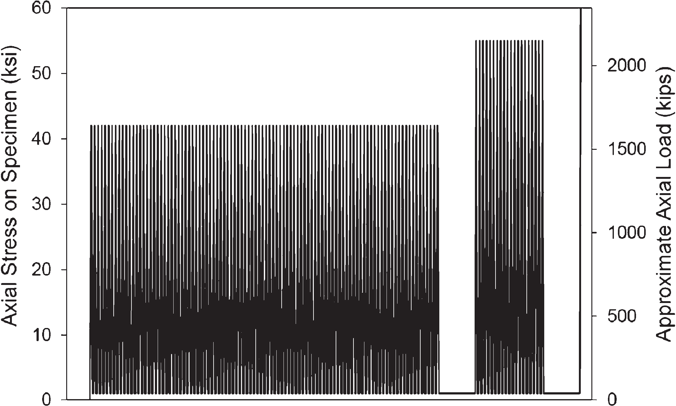
Illustration of load cycles.
The loading history shown in Fig. 2 has purposeful pauses shown at the beginning and end of the first loading block, as the Contractor will have to pause for the PAUT inspection. The PAUT inspection is being performed to understand if the loading protocol has caused the internal rejectable discontinuities to lengthen or not.
Electro-slag welding
Electroslag welding is used mainly to join low carbon steel plates and/or sections that are very thick in a vertical or close to vertical position. Federal Highway Administration (FHWA) found that electroslag welding, because of the very large amounts of confined heat used, produced a coarse-grained and brittle weld and in 1977 banned the use of the process for many applications. The FHWA commissioned research from universities and industry and Narrow Gap Improved Electro Slag Welding (NGI-ESW) was developed as a replacement. The FHWA moratorium was rescinded in 2000. The latest version of electroslag welding, ESW-NG (the NG stands for narrow gap – about 3/4 inch), is currently accepted by AASHTO for welding common types of bridge steels and is included in the bridge welding code [2].
An ESW-NG weld consists of coalesced alloy-cored wire, base metal, and a consumable wire guide. An electric arc is initially struck by wire that is fed into the desired weld location and then flux is added. Additional flux is added until the molten slag, reaching the tip of the electrode, extinguishes the arc. The wire is then continually fed through a consumable guide tube into the surfaces of the metal workpieces and the filler metal are then melted using the electrical resistance of the molten slag to cause coalescence. The wire and tube then move up along the workpiece while a copper retaining shoe that was put into place before starting is used to keep the weld between the plates that are being welded. It can also be used on structural steel if certain precautions are observed.
Solidification cracking is a phenomenon in which a weak alloy is formed at the grain boundaries during the solidification process. This may be caused by rapid cooling, excessive shrinkage, excessive penetration due to high welding voltage, and susceptible weld chemistry. Solidification centerline cracking, also known as hot cracking, has been identified in several locations in this weld. When excavated, these indications have ranged from 10 mm in length to 300 mm in length with significant through thickness dimensions (5–25 mm).
When the grain structure of an electroslag weld was examined at mid wall and along its length, the grain pattern is columnar, which is a conical or pyramidal shape, (Fig. 3), with 2 mm – 5 mm long grains beginning at the fusion boundary and angling up at 45 degrees to meet in the middle. The grains in the center exhibit a vertical orientation and tend to be long and skinny.
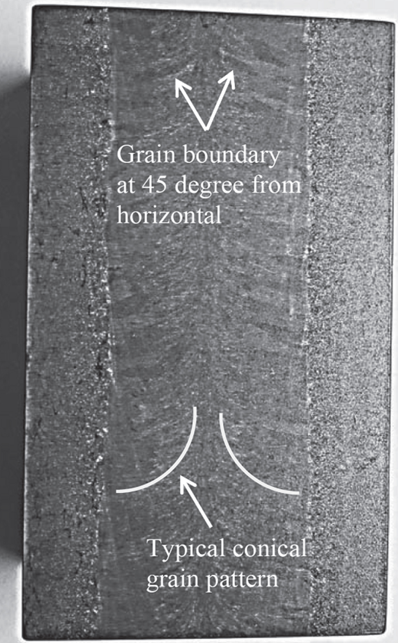
Typical Grain Structure of Electroslag.
The indications discovered in the electroslag welds follow this pattern in almost all occasions. The transverse indications tend to be left and right of center, and angled roughly 45 degrees up. The indications along the centerline tend to be long, straight and perfectly vertical. Figure 4 shows typical indications.

Typical transverse indications found in weld.
Unlike conventional ultrasonic testing (UT) probes that contain a single transducer element, phased array ultrasonic testing (PAUT) probes contain multiple small individual transducer elements (probes typically contain arrays with 16 to 256 elements) that can be pulsed individually using computer-calculated timing (“phased or delay laws”). The beam from a phased array unit can be electronically swept through multiple angles (usually in the range of 45–75°) at the same time in order to scan a volume of weld without moving the probe toward and away from the weld joint as done in conventional UT. This is accomplished by pulsing each individual transducer element at slightly different times and thus the sound from each element pulse interacts with one another creating a single wave-front at a given distance based on parameters set by the technician and PAUT focal laws. Figure 5 shows a general overview of how multiple transducer elements can be used to create a wide ultrasonic beam capable of identifying a defect in a volume of welded material.
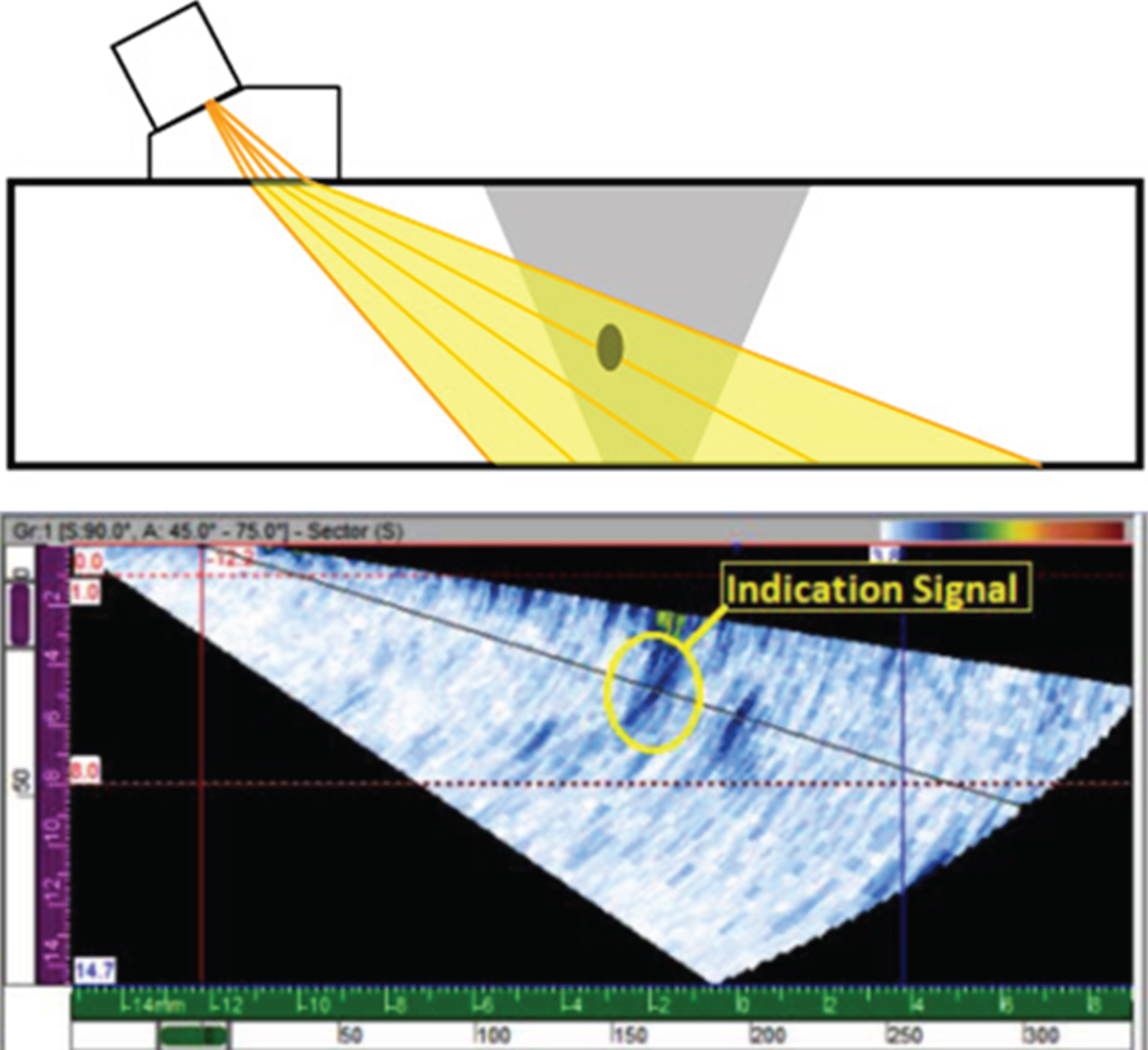
Typical PAUT sound beam.
Scan plans are developed to visualize and tune the setback distance (fixed point from a specific location), sound wave path, depth of focus, and interactions with geometries within the sound path. Figure 6 shows how different scan plans can be used to map different areas in the weld while the probe remains fixed.

Different PAUT Scan Plans to cover the weld.
PAUT scanning on this project uses an Olympus OmniScan MX2 flaw detector combined with a manual mini wheel encoder [3]. The mini wheel encoder (or string encoder) allows the PAUT data to be collected, stored, and correlated to a known location along the deck panel. The fixed set back is obtained by either a straight edge mounted to the panel or a scanning apparatus which holds the probe in a fixed position from the weld toe as it traverses along the weld. The PAUT information is encoded and saved by the OmniScan MX2 flaw detector and then exported to a computer for further post-processing analysis and interpretation.
Post-processing analysis of the acquired PAUT data is done using OmniPC software or TomoView software. OmniPC and TomoView are PC-based software for the visualization and analysis of PAUT signals. The software allows the PAUT technician to generate detailed reports summarizing the results of the PAUT examination and allows the weld profile to be visualized from multiple orientations to accurately visualize any weld indications.
PAUT equipment
The PAUT equipment used to for this examination consisted of an Olympus OmniScan MX2 16:64 (16 pulsars and 64 channels) displayed in A, B, C, S, linear scans, or a combination thereof (2). The aperture was fitted to a 55° shear wave wedge with elements oscillating at 5.0 MHz. A linear digital encoder recorded data for post processing using TomoView and/or OmniPC software.
PAUT calibration
Ultrasonic equipment used to identify weld flaw detection and weld sizing must be calibrated prior to inspection. The PAUT equipment was first calibrated using a Standard IIW (International Institute of Welding) block to calibrate the wave velocity, wedge delay, and angle corrected gain (ACG or “sensitivity”). The time corrected gain (TCG) was established on a standard 1.5 mm diameter side drilled hole block. Furthermore, the digital encoder was calibrated to ensure the measured distance was within±1% of the actual distance the probe traveled along the weld (3).
PAUT technique sheet
Table 1 outlines the details of the PAUT procedure including the equipment used, the calibration blocks, and the scan plan details.
PAUT technique sheet summary
PAUT technique sheet summary
PAUT was performed before cycling and after the first block of 100 cycles. Due to the number of strain gauges, other sensors and the overall footprint of the aperture, access and scanning distance was very limited. Distance of scanning was approximately 50 mm to 100 mm. The specimen was scanned from both faces primarily from the top down the length of weld at an aggressive angle attempting to be normal to the discontinuities as much as possible. In several instances, the scanning had to be performed by hand in lieu of using a fixed jig due to access constraints.
Figure 7 shows an image of the scan plan that was utilized for this joint at different setbacks in order to provide the best coverage of the entire weld area.

Scan Plan with different setbacks utilized to cover the weld.
Prior to performing the PAUT, conventional UT was performed in order to locate the existing indications and select a reasonable scanning reference as the indications were originally classified under AWS D1.5 with an indication rating anywhere from +12- dB to +24 dB. The conventional UT was performed with AWS compliant transducers and wedges oscillating at 2.25 MHz. A baseline report for conventional UT dB rating was recorded for comparison after cycling, however the results were mixed. Some indications provided more sound reflection, while others exhibited less. An overall 10–15 percent full screen height increase in noise to signal rating was observed from the baseline scanning.
The aperture utilized was a 5L-60 with 1 mm pitch and Sectorial and Linear scans were utilized. In addition to the 5L-60, a 5L-16 was utilized for comparison scanning; however due to the limited focusing distance ability and resolution, the data did not prove useful. In addition, the linear scans did not provide any specific data for the indications as the set back distance could not be changed due to access. Changing the firing sequence also did not yield any further improvement. Sizing methodology utilized was a 6 dB drop.
The sectorial scan results of the PAUT before and after cycling are shown in Table 2 below.
Summary of PAUT indications
In Table 2, the indication length and height specify the dimensions of the discontinuity in the weld; and the indication depth identifies the location of the discontinuity within the body of the weld.
Figures 8 through 12 show a screen shot of the PAUT post-processing. The top right is the A-scan which depicts the signal strength (vertical axis) versus the distance/time of ultrasound signal (horizontal axis); this is commonly seen in conventional UT. The top left is the S-Scan which is a two dimensional view of the signal amplitude and the location. The bottom is the C-scan which shows the top view of the indications in the weld.
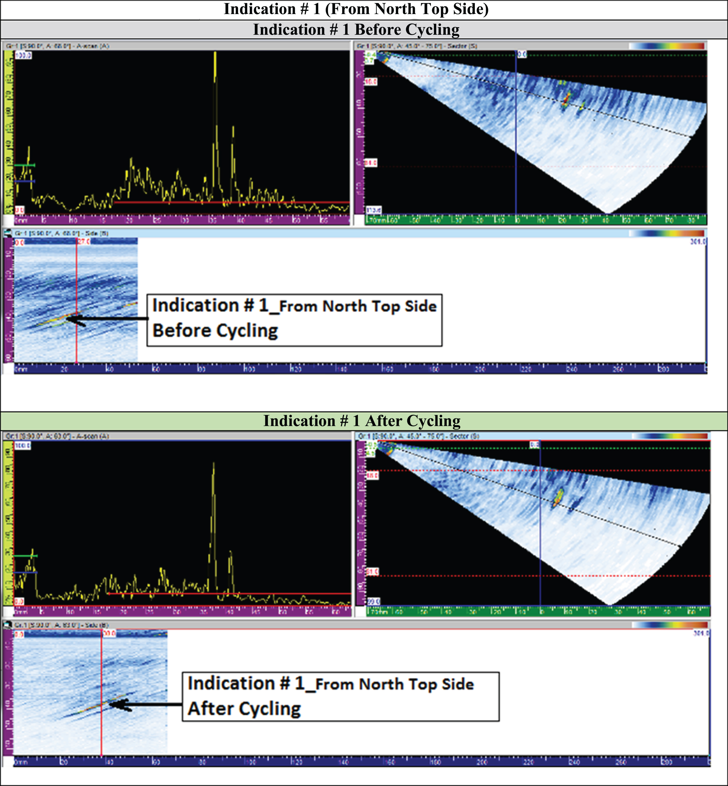
PAUT Results of Indication # 1.
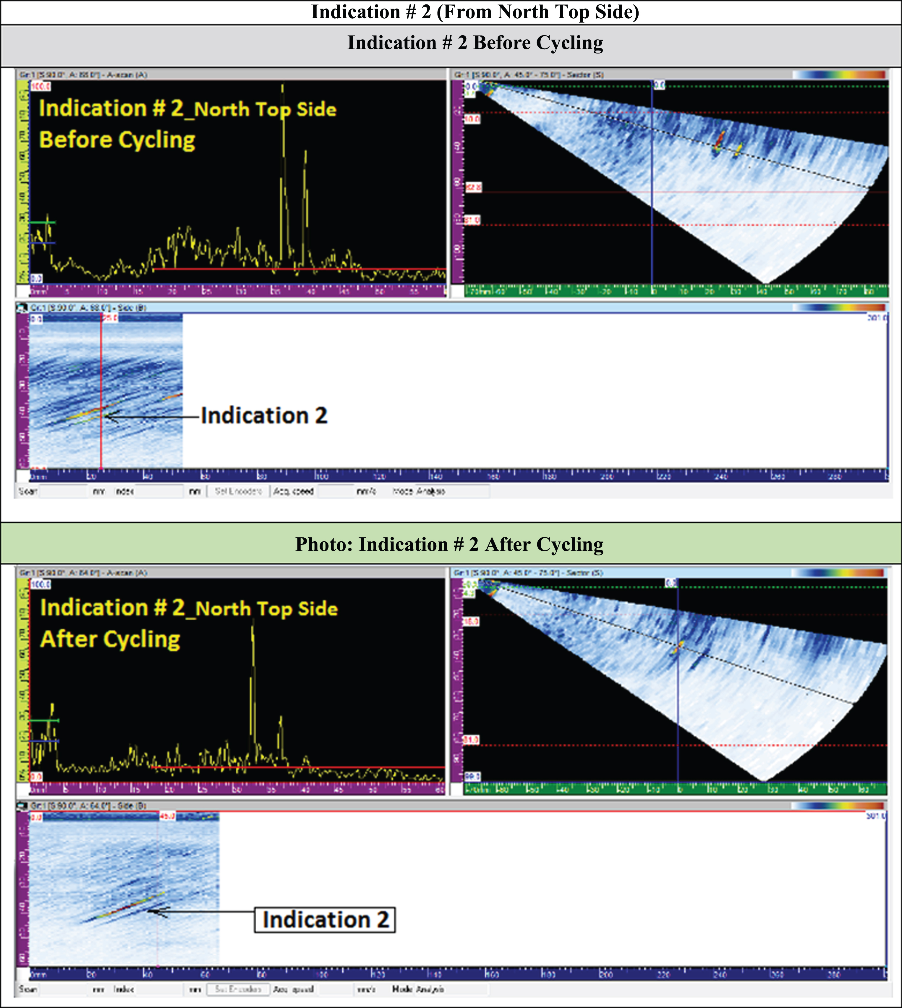
PAUT Results of Indication # 2.

PAUT Results of Indication # 3.
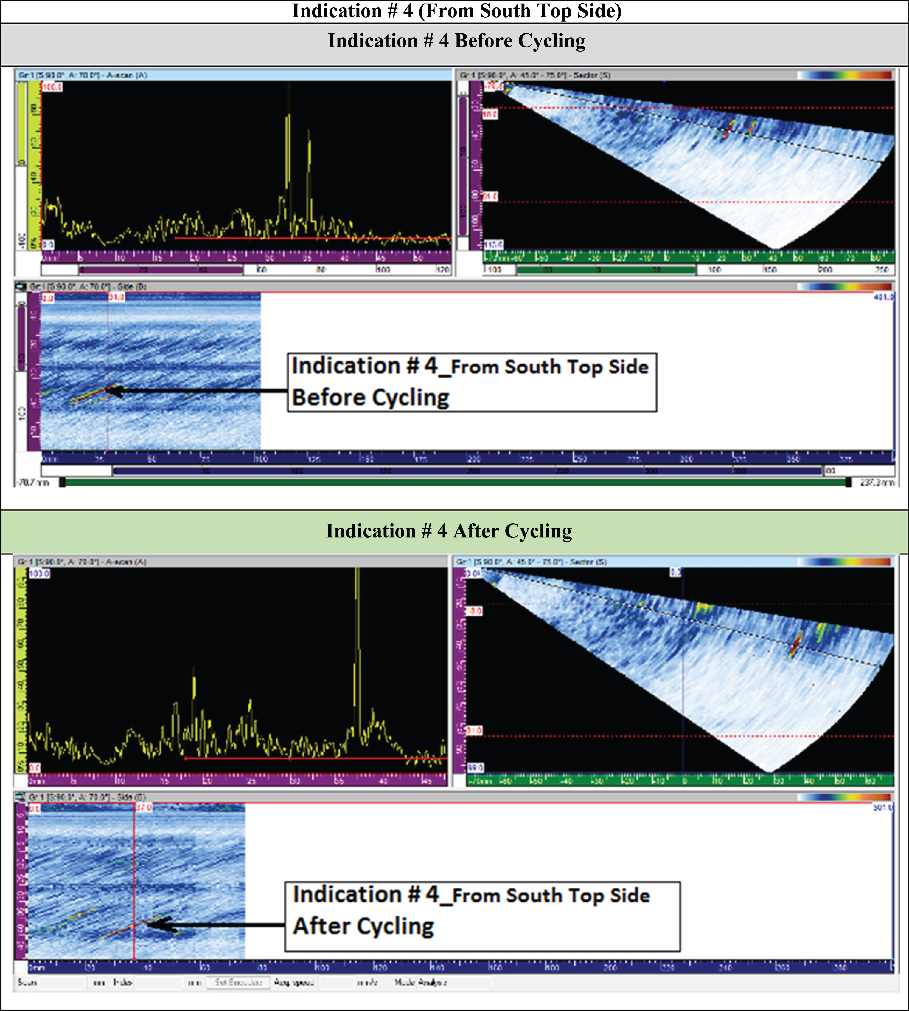
PAUT Results of Indication # 4.
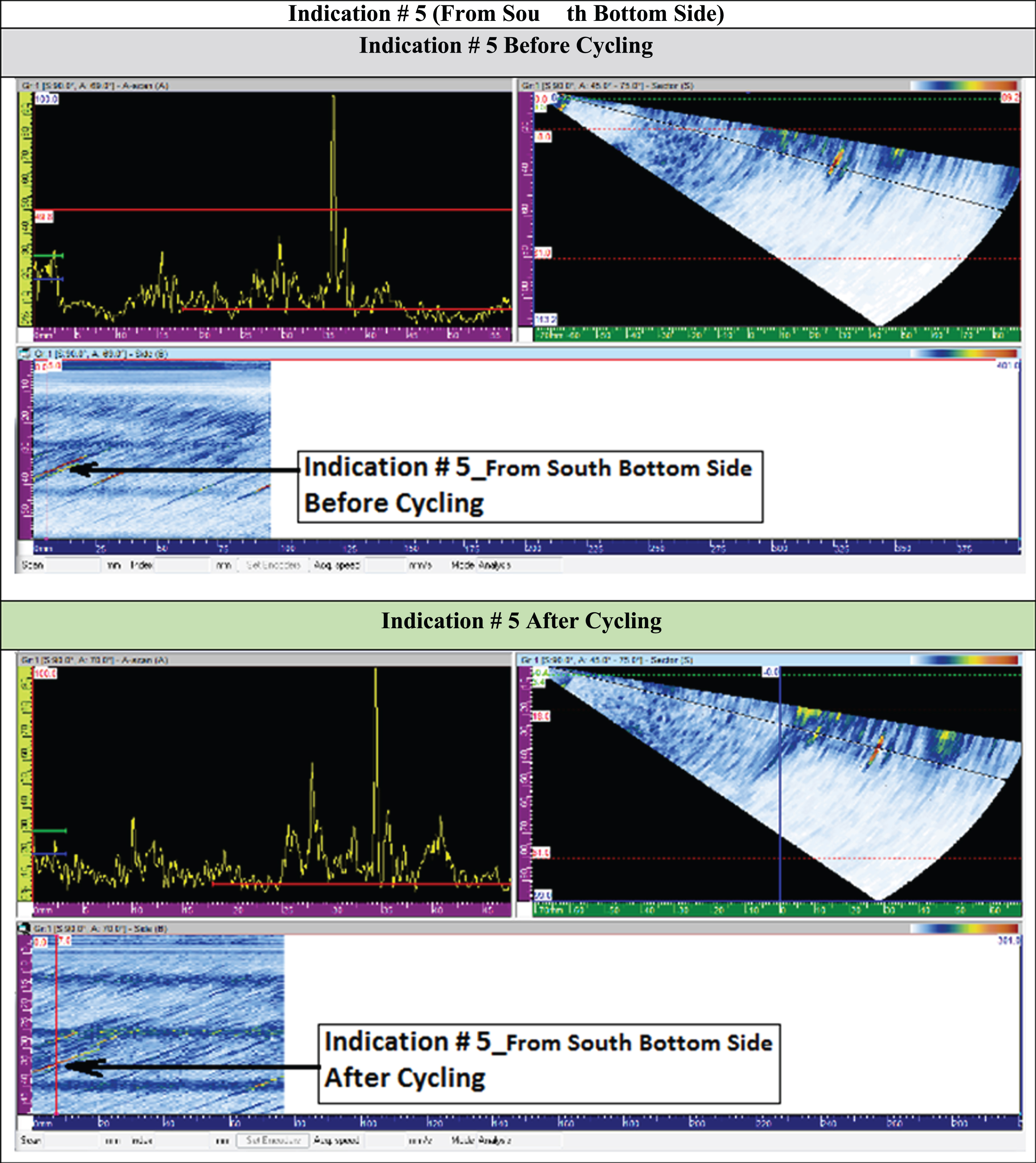
PAUT Results of Indication # 5.
The PAUT result for each indication is shown before and after cycling and the results have been summarized in Table 2. Note that the results of the PAUT before and after cycling show an increase in dimensions of the recorded indications by an average of 6–8 mm or approximately 50% of the original dimensions.
Phased array ultrasonic testing is not designed to replace more traditional UT methods; however it is another tool in the NDT tool box that has some unique advantages. Speed – Automatic/semi-automatic scanning allows for a faster scan rate over a larger volume of material facilitating an increased shop production rate. Flexibility – A single probe can be used to scan small areas or larger volumes by adjusting the scan plan. Complex inspection – Multiple scan plans can be created to investigate complex geometrieand/or large volumes of materials that may be otherwise inaccessible. Increased probability of detection – The ability to test welds with multiple angles from a single probe greatly increases the probability of detection of anomalies. Electronic focusing permits optimizing the beam shape and size at the expected defect location, as well as further optimizing probability of detection. Encoding – Digital encoders allow the full spectrum of UT data to be saved for post-processing and shared with others for independent analysis. Unique imaging – S-scans permit easier interpretation of an indication’s size and location in the sample.
The advantages of PAUT do not come without some challenges. Recently Incorporated into Codes – AWS D1.5 welding committees have worked to incorporate PAUT in the 2015 code. Expensive equipment – Compared to conventional, single-element ultrasonic testing systems, phased array instruments and probes are more complex and expensive (approximate 2x to 5x the cost of conventional UT). Skilled operator – Phased array technicians require more experience and training than conventional UT technicians. Time-intensive – Data analysis and post-processing time increases with the large amount of data collected by PAUT.
With the introduction of the PAUT into the 2015 edition of the AWS D1.5 code, PAUT is becoming increasingly common for inspection of welds in steel bridges. PAUT is increasingly being used in lieu of Radiographic Testing (RT) since it does not include the safety and schedule restrictions of RT. PAUT is also most cost-effective for situations with large amounts of welds because it’s speed and flexibility allow for post-processing to occur outside the shop floor. Furthermore, PAUT is the preferred non-destructive method for complex inspections such as Partial Joint Penetration Welds in Orthotropic decks.