
Abstract
Developed by the PCI northeast, northeast extreme tee (NEXT) beams provide a solution to achieve rapid construction and minimal bridge maintenance. The NEXT beams have shown several advantages over the traditional I-shaped and adjacent box beam sections. In current practices, the design live load moment in an I- or box-beam in skewed bridges is calculated in accordance with the LRFD approximation method with a live load distribution factor (LLDF) and a skew correction factor (SCF). As a new bridge section, live load distributions in NEXT beam bridges however have not been addressed in the LRFD bridge design specifications. In this sense, this paper intends to explore the lateral distribution of live load moment in simply supported skewed NEXT beam bridges, aiming to assess the suitability of the LRFD approximation method for NEXT beam bridges. Through employing validated finite element (FE) analyses, a total of 160 NEXT beam bridges with five different skew angles (i.e., 0° to 40° with 10° intervals) were investigated in this paper by a comprehensive parametric study. The parameters of beam section, span length, number of beams in a bridge were considered in the study. A method for computing the FE-SCFs for skewed NEXT beam bridges was proposed. The FE-SCFs were compared to the LRFD-SCFs by percent errors. Results from this study showed that the LRFD-SCFs governed the FE-SCFs when the skew angle is ≤30°. However, it was observed that some FE-SCFs exceeded the LRFD-SCFs by up to 5.65% when the skew angle is 40°, indicating that using LRFD-SCFs may lead to an unsafe design in this case. It is recommended that the LRFD-SCFs be used for NEXT beam bridges with skew angles ≤30°, whereas the LRFD-SCFs should be increased by 6% in order to achieve a sufficient safety margin for NEXT beam bridges with a skew angle of 40°.
Introduction
The rehabilitation or replacement of deficient bridges can be very expensive, which involves both direct and indirect costs [1, 2]. In the past decades, significant efforts have been made by various researchers to reduce the bridge repair or replacement costs and also to enhance the sustainability of bridges. Utilizing precast concrete elements can improve the quality and durability of bridge elements and also accelerate the bridge construction process, thus reducing the costs [3, 4]. The development of the northeast extreme tee (NEXT) beams was one of such endeavors. In 2006, the PCI northeast bridge technical committee initiated the development of the NEXT beam section [5]. Figure 1 shows a typical bridge section with NEXT beams [5]. The first NEXT beam bridge built over the York River in York, Maine was reported by Gardner and Hodgon (2013) [6]. For this seven-span NEXT beam bridge, the estimated time savings for the erection of beam superstructures were about 7 weeks, as compared to the Northeast Bulb Tee (NEBT) beam superstructures [6]. In addition to the time savings on the beam erection, the NEXT beam is able to accommodate utilities between stems and therefore there is no need for parapet attachments [6]. It is important to note that the top flange of the NEXT beam can work as formwork for the top cast-in-place (CIP) bridge deck, which also saves the time and costs for installing and stripping the formwork [5]. In recognition of the aforementioned advantages of NEXT beams over other type beams (e.g., Bulb Tee beams), the NEXT beams are gaining increased attentions, especially for bridge replacement projects, to the bridge engineering community.
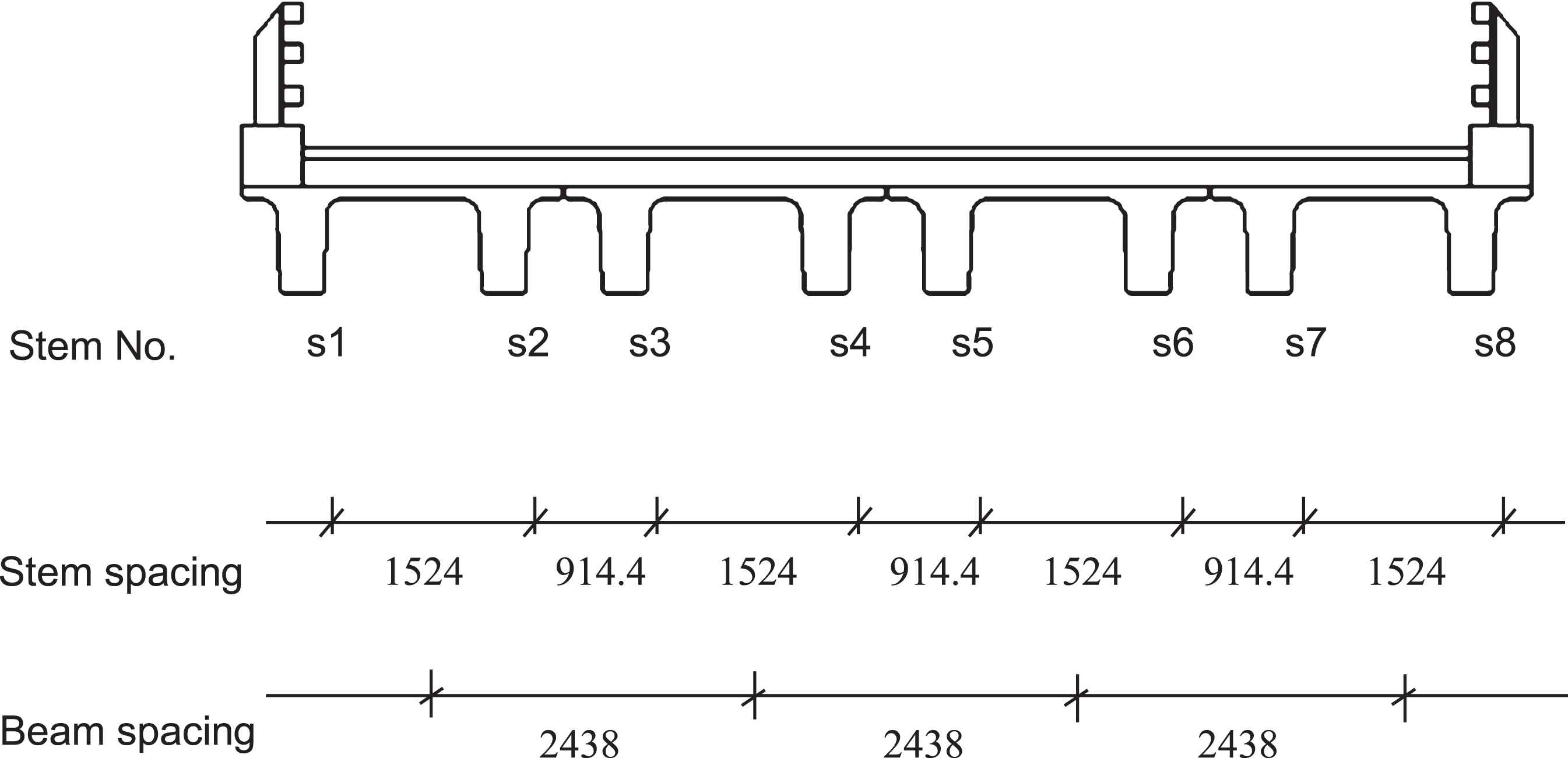
Transverse bridge section (Unit: mm; Adapted from [5]).
Figure 2 illustrates the NEXT “F” beam sections [5]. Currently, there are four beam designations, namely, NEXT 24F, NEXT 28F, NEXT 32F and NEXT 36F [7]. The beam depths for NEXT 24F, 28F, 32F, and 36F are 609.6 mm (24 in), 711.2 mm (28 in), 812.8 mm (32 in), and 914.4 mm (36 in), respectively; for each beam depth, the minimum and maximum beam widths are 2438 mm (8 ft) and 3658 mm (12 ft), respectively; note that the spacing of the two beam stems is 1524 mm (5 ft) on centers for all beam sections [5, 7]. Details of NEXT “F” beam sections and sectional properties can be found in [5] and [8]. It is worth mentioning that the constant stem spacing (i.e., 1524 mm) could lead to unequal stem spacing in a NEXT beam bridge (see Fig. 1), which makes the current LRFD approximation method of live load distribution factor for moment not applicable to the NEXT beams. Therefore, it becomes a challenge when determining the live load moment in the exterior or interior beam of a NEXT beam bridge. At this point, the PCI Northeast uses a conservative method for the determination of live load distribution factor (LLDF) for moment per lane for a NEXT beam, that is, using the average stem spacing to compute the LLDF for a stem, which is subsequently doubled to calculate the LLDF for the entire NEXT beam [7]. However, this method can be over-conservative [7, 8]. Huang and Davis (2017) evaluated the LLDFs for moment in various NEXT beam bridges through a parametric study by using refined analyses through simplified and detailed finite element (FE) simulations [8]. The FE-LLDFs for moment as determined from the FE analyses were compared to the LRFD types “i”, “k”, and “h” distribution factors. The results showed that the LRFD types “i” and “k” sections are more applicable for NEXT beam bridges and the entire NEXT beam can be treated as a stringer when computing the LRFD-LLDFs [8]. This study was a significant piece of work, however, only right bridges were considered.
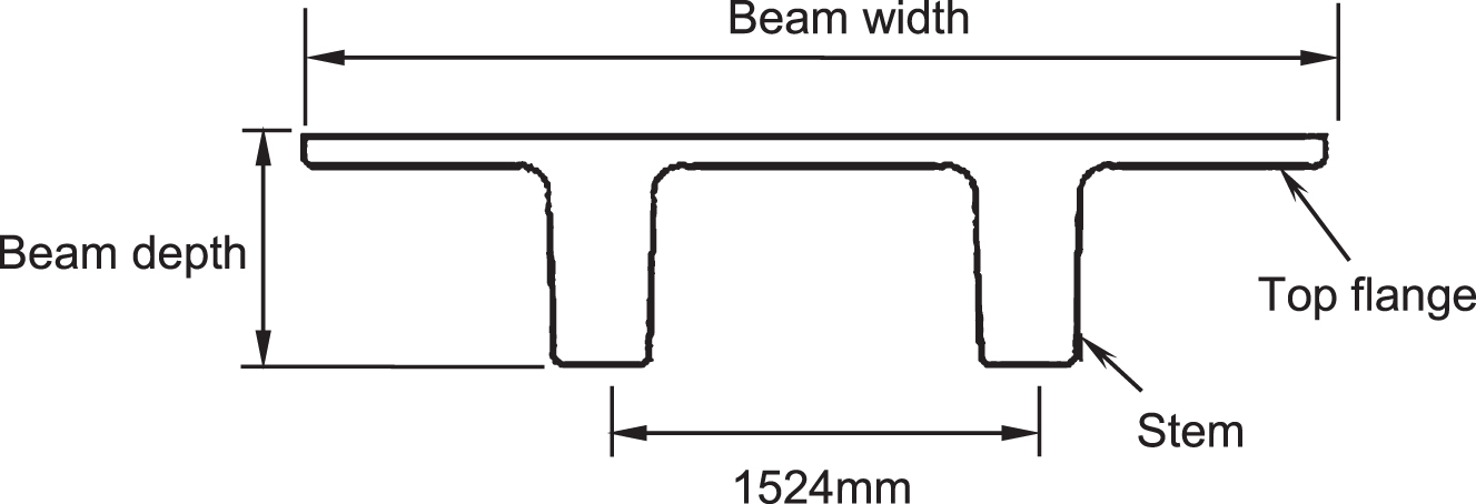
NEXT “F” beam cross section (Adapted from [5]).
In real situations, many bridges require skewed support lines due to the site constraints. The presence of skew can lead to more complicated live load distribution than that in right bridges [9]. To date, the live load distribution for moment in the skewed NEXT beam bridges has not been well addressed. Recently, few studies on the live load distribution in skewed NEXT beam bridges with integral abutments were reported [10–12]. Huang and Davis (2018) investigated the skew reduction factors (SRF) for moment in skewed NEXT beam bridges with integral abutments, where two types of bridges were explored: one is with four 2438 mm (8 ft) wide NEXT beams, whereas the other is with three 3658 mm (12 ft) wide NEXT beams [12]. A total of 96 NEXT beam bridges were explored through detailed FE analyses with solid brick elements in [12]. Results showed that the LRFD-SRFs governed the FE-SRFs for all bridges with a skew angle ≤30°; for some bridges with higher skew angles (i.e., 40°, 50°), the FE-SRFs exceeded the LRFD-SRFs by up to 4% [12]. Note that Huang and Davis (2018) only investigated the NEXT bridges with integral abutments. In many cases, bridges were designed and built as simply-supported span(s) without integral abutments. It is important to point out that, to date, the lateral distribution of live load moment in simply supported NEXT beam bridges with skewed support lines is still unclear due to the limited research, which poses a challenge for bridge engineers on the design of such bridges. Thus, this paper aims to investigate lateral live load distribution through a comprehensive parametric study on 160 bridges consisting of four different bridge types, and therefore to assess the suitability of the AASHTO LRFD approximation method for the simply supported skewed NEXT beam bridges. The results from this study can provide a useful guidance for bridge practitioners on the analysis and design of skewed NEXT beam bridges and also can serve as an important source for the future update of relevant design guidelines and/or specifications.
Scope of work
Both right and skewed bridges are analyzed in this paper. A total of four different types of bridge sections, as shown in Fig. 3, are examined for the right bridges. For each bridge type, four different beam sections (i.e., NEXT 24F, 28F, 32F, and 36F) are considered with various beam lengths, as summarized in Table 1. As can be seen, a total of 32 right bridges are explored. In order to determine the skew angle effects on the live load distribution, additional four different skewed bridges (i.e., skew angle = 10°, 20°, 30° and 40°) are analyzed for each right bridge, leading to a total of 160 bridges being investigated in this paper. Note that the PCI Northeast set 30° as a preliminary maximum limit for skewed NEXT beam bridges due to the concern of potential cracking at release in the fabrication plant; however, the PCI Northeast also stated the skew angle may be possible to exceed 30° [7]. For this reason, only skew angles up to 40° are considered herein.
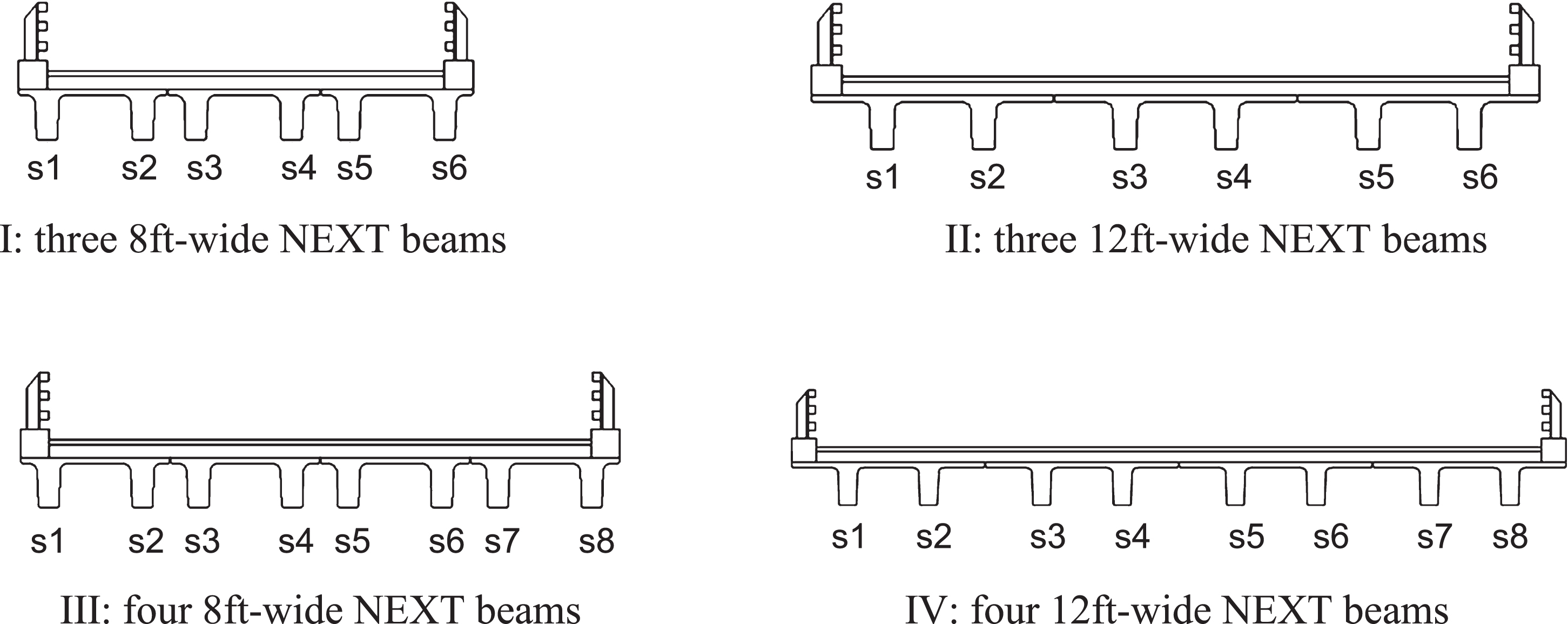
Types of NEXT bridge sections (Adapted from [5]).
Bridge parameters for the 32 right NEXT beam bridges
In the past decades, finite element (FE) analyses have been successfully employed in the structural analyses of various bridges [e.g., 8, 13–16]. The bridge superstructures have been idealized in several ways, e.g., two dimensional (simplified) or three dimensional (detailed) FE models [e.g., 8]. In the detailed FE modeling, eight-node solid elements with three degrees of freedom at each node are used to model the bridge beams and deck, where the deck and beams are fully connected by using slave- master constraints [e.g., 8]. For the simplified analyses, bridge beams were simply modeled as two-node space-frame elements, whereas the concrete deck was simulated by 4-node quadrilateral shell elements [e.g., 8, 17–19]. Compared to the detailed FE simulation, the simplified FE modeling is much easier to build the FE bridge model and it requires much less computational costs. In addition, it has been verified by the author that the simplified FE analyses of NEXT beams bridges yielded comparable results to that produced by the detailed modeling [8]. For these reasons, the simplified FE modeling technique in Huang and Davis (2017) [8] is employed with confidence in this study, as follows:
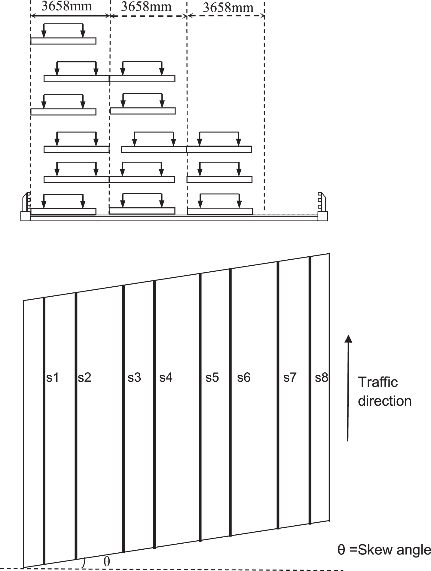
In this paper, each NEXT beam is modeled with two frame lines (spaced at 1524 mm on centers) by 2-node frame elements with 6 degrees of freedom at each node, where a half section of the NEXT beam is assigned to each frame line; pinned and roller boundary conditions are assigned to the end nodes of the frame lines; the 203.2 mm (8 in) thick concrete deck is modeled with 4-node shell elements; note that the centroid of the deck coincides with the beam stem centroid. Figure 4 shows an FE bridge model in CSiBridge. Concrete compressive strengths for the NEXT beam and concrete deck are assumed as of 55.16 MPa (Ebeam = 37.38 GPa) and 27.58 MPa (Edeck = 26.43 GPa), respectively; and a Poisson’s ratio of 0.2 is assumed for the deck and beam concrete [8]. In accordance with the LRFD specifications [20], the HL-93 loading is used as design live load in this study. The HL-93 loading consists of a design truck (HS-20) coincident with a 9.34 kN/m (0.64 kip/ft) design lane load [20]. The CSiBridge program [21] is used for FE analyses, in which the 9.34 kN/m (0.64 kip/ft) design lane load is uniformly distributed as a pressure load over the 3.048 m (10 ft) wide design lane, whereas the design truck is mimicked as six concentrated loads and simulated as a moving load. Note that a dynamic load allowance of 33% is applied to the design truck only, as per LRFD A3.6.2.1 [20]. Figure 5 shows the live load configurations for one-, two-, and three-lane loaded profiles. Note that the required number of lanes is governed by the bridge clear width [20]. In order to find the maximum moments in the beam stems, each lane configuration is moved by 304.8 mm (1 ft) increments in the bridge transverse direction (perpendicular to the traffic direction). Once the center of the load configuration exceeds the bridge centerline, load explorations were terminated due to the symmetry of the bridge. Per LRFD specifications, multiple presence factors were applied to the stem moments [20].
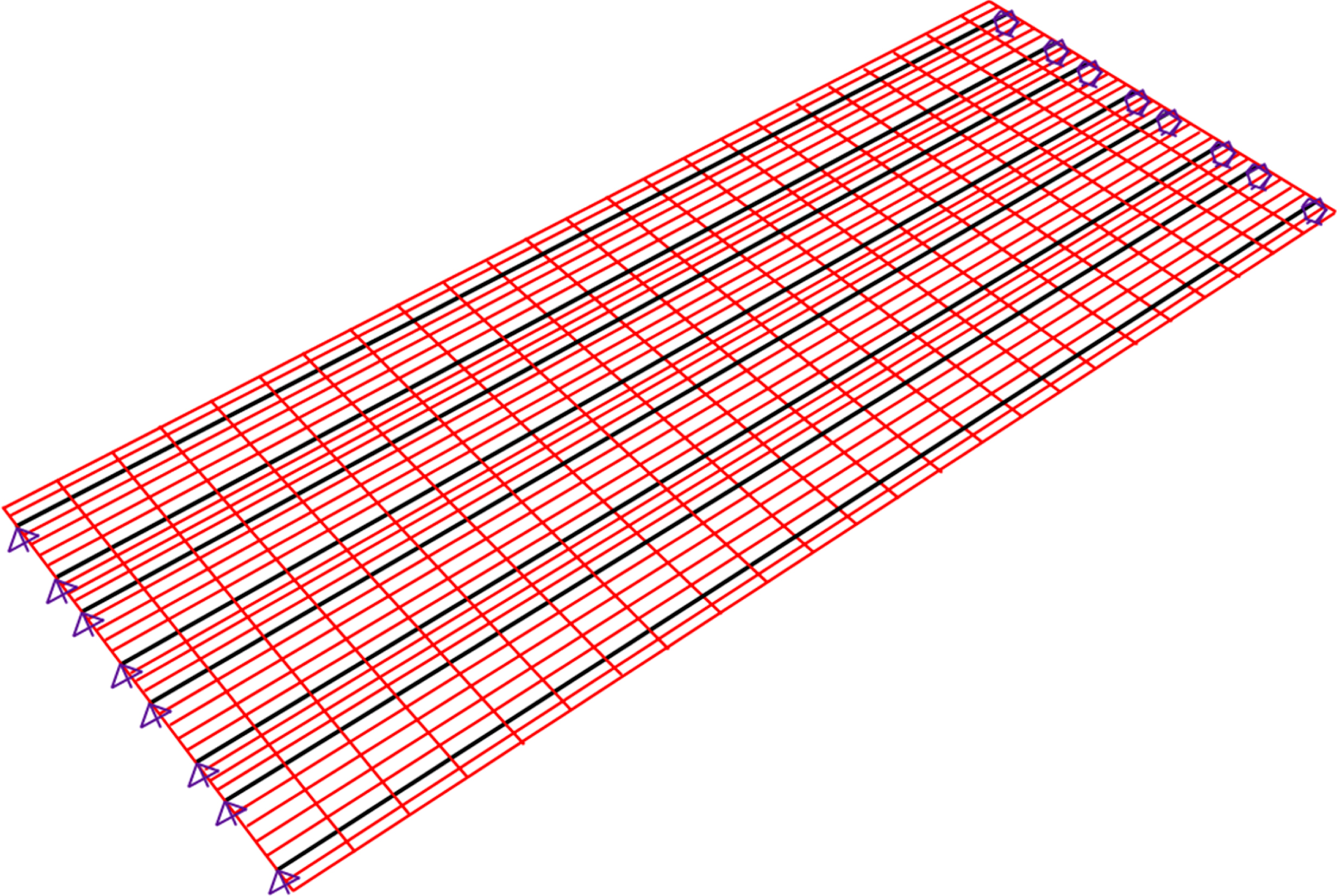
FE bridge model (Adapted from CSiBridge [21]).
Live load configurations (Adapted from [8]).
In accordance with the AASHTO LRFD specifications, the live load moment in a beam in a skewed bridge may be reduced by a skew correction factor (SCF), which is applied to the girder moment (i.e. moment per lane multiplied by a LLDF) [20]. The calculation of the SCF for moment (for types “i” and “k”) is provided in the LRFD Bridge Design Specifications, as follows [20]:
Where, θ is the skew angle of the support line. When θ< 30°, c1= 0; when θ> 30°, c1 is calculated as follows:
Where S = girder spacing (mm); L = span length (mm); ts = deck thickness (mm); Kg is calculated as follows:
Where A = area of stringer, beam or girder (mm2); I = the moment of inertia of beam (mm4); eg is distance between the centers of gravity of the basic beam and deck (mm); EB = modulus of elasticity of beam materials (MPa); ED = modulus of elasticity of deck materials (MPa).
After running the simplified FE analyses, the maximum bending moment envelope of each stem under respective lane-loaded cases were extracted to compute the FE-SCFs for moment in the NEXT beams (i.e., exterior or interior beam). The FE-SCFs for moment in the exterior or interior beam in a skewed bridge is calculated as follows:
Where θ= skew angle (see Fig. 5); n = 1, 2, 3 for one-, two-, and three-lane loaded, respectively. Note that for type I bridges, only one-lane loaded was considered; for type II and III bridges, both one- and two-lane loaded cases were considered; for type IV bridges, one-, two-, and three-lane loaded cases were considered.
For the exterior beam in all types of bridges (i.e., types I, II, III and IV): the larger of the maximum moments in stems “s1” & “s2” of the skewed bridge the larger of the maximum moments in stems “s1” & “s2” of the corresponding right bridge the maximum moment in stem “s3” of the skewed bridge the maximum moment in stem “s3” of the corresponding right bridge the larger of the maximum moments in stems “s3” & “s4” of the skewed bridge the larger of the maximum moments in stems “s3” & ‘s4” of the corresponding right bridge
For the interior beam in type I or II bridges (consisting of three NEXT beams):
For the interior beam in type III or IV bridges (consisting of four NEXT beams):
The LRFD-SCFs for moment were computed with Equations (1) – (4) for all bridges, whereas the FE-SCFs were computed with Equation (5). Figure 6 shows the comparisons of LRFD- and FE-SCFs for a type III bridge with four 2438 mm (8 ft) wide NEXT 32F beams. The bridge has a span length of 24079 mm (79 ft). Only one- and two-lane loaded cases were explored. As can be seen, the FE-SCFs decrease as skew angle increases. For a skew angle ≤30°, the LRFD-SCFs govern the FE-SCFs, which indicates the LRFD-SCFs provide a sufficient safety margin. However, it is observed that some of the FE-SCFs (e.g., exterior beam under one-lane loaded case) slightly exceed the LRFD-SCFs at 40° skew angle. Figure 7 shows the comparisons of LRFD- and FE-SCFs for a type IV bridge with four 3658 mm (12 ft) wide NEXT 36F beams. The bridge has a span length of 20726 mm (68 ft). One-, two- and three-lane loaded cases were explored. As can be seen, the FE-SCFs decrease as skew angle increases; the LRFD-SCFs govern the FE-SCFs when skew angle ≤30°, whereas, most of the FE-SCFs exceed the LRFD-SCFs at 40° skew angle. The largest difference is observed for the exterior beam under one-lane loaded case, where the FE-SCF is 5.65% larger than the LRFD-SCF. Note that in the legends of Figs. 6 & 7, “ext” = exterior beam and “int” = interior beam.

LRFD-SCFs vs. FE-SCFs (type III bridge: 32F-8-79).
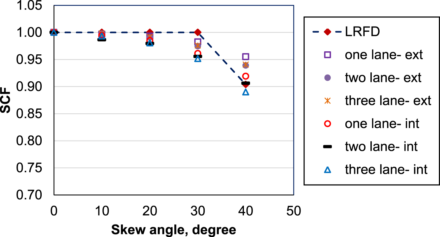
LRFD-SCFs vs. FE-SCFs (type IV bridge: 36F-12-68).
In order to better observe the differences between the FE-and LRFD-SCFs, percent errors are computed for all cases, as follows:
If an error% is less than zero, it means the LRFD-SCFs are conservative. Otherwise, using LRFD-SCFs may lead to an unsafe design.
Figures 8, 9, 10, 11 show the percent errors between the LRFD- and FE-SCFs for type I, II, III, and IV bridges, respectively. In these figures, the title of X-axis is named with “beam section–beam width–span length”. Taking “24F-8-50” as an example, “24F” means the beam section is NEXT 24F beam; “8” means the beam width is 8 ft (2438 mm) wide; and “50” means the bridge span is 50 ft (15240 mm) long. The figure legend is defined by “bridge type-skew angle-lane loaded case-exterior or interior beam”. For example, “I-10-two-ext” refers to the bridges with type I bridge section (i.e, three 2438 mm wide beams) with a skew angle of 10° and the percent error is computed for two-lane loaded cases for the exterior beam. As can be seen, percent errors are greater than zero for all data points in these four figures, which means the LRFD-SCFs always govern the FE-SCFs. Therefore, using the LRFD-SCFs should provide sufficient safety margins for skew angle ≤30°.
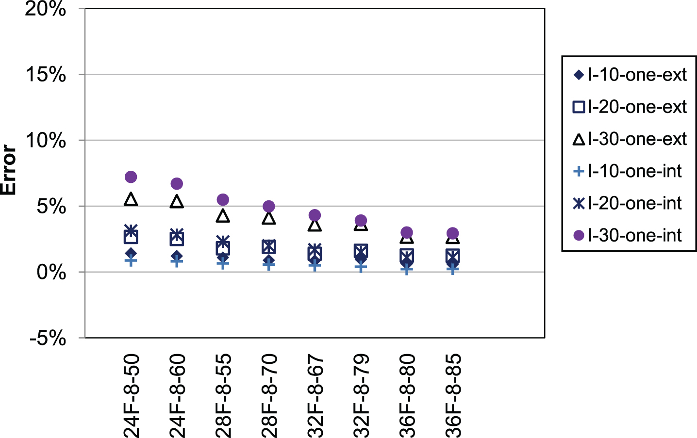
Error% between LRFD- and FE-SCFs (Type I bridges, skew angle ≤30°).
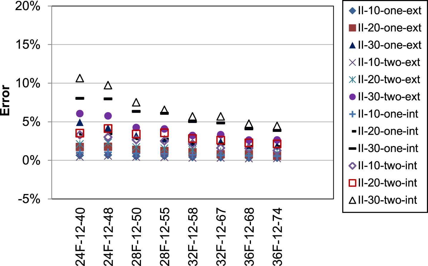
Error% between LRFD- and FE-SCFs (Type II bridges, skew angle ≤30°).
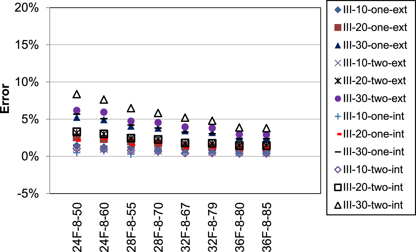
Error% between LRFD- and FE-SCFs (Type III bridges, skew angle ≤30°).

Error% between LRFD- and FE-SCFs (Type IV bridges, skew angle ≤30°).
The percent errors between the LRFD- and FE-SCFs for bridges with a skew angle of 40° are plotted in Figs. 12 and 13. Both figures are plotted in the same way as Figs. 8–11: the title of X-axis is named after “beam section–beam width – span length”, whereas the legend is defined by “bridge type-skew angle-lane loaded case-exterior or interior beam”. Figure 12 shows the percent errors between the LRFD- and FE-SCFs for type I and III bridges (with 2438 mm wide beams). As can be seen, the percent error decreases as the beam depth increases. For the bridges with NEXT 24F and 28F beams, percent errors are greater than or approximately equal to zero. However, a few negative percent errors are observed for the bridges with NEXT 32F and 36F beams, with a minimum – 2.2% error. Figure 13 shows the errors between the LRFD- and FE-SCFs for type II and IV bridges (with 3658 mm wide beams). In this figure, negative percent errors are observed for all bridges, with a minimum – 5.65% error. Negative percent errors imply that using LRFD-SCFs can lead to unsafe design. Therefore, it is suggested the LRFD-SCFs be increased by 6% for NEXT beam bridges with a skew angle of 40°.
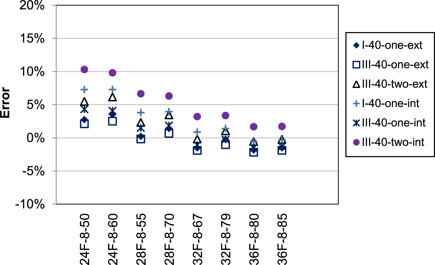
Error% between LRFD- and FE-SCFs (Type I and III bridges, skew angle = 40°).
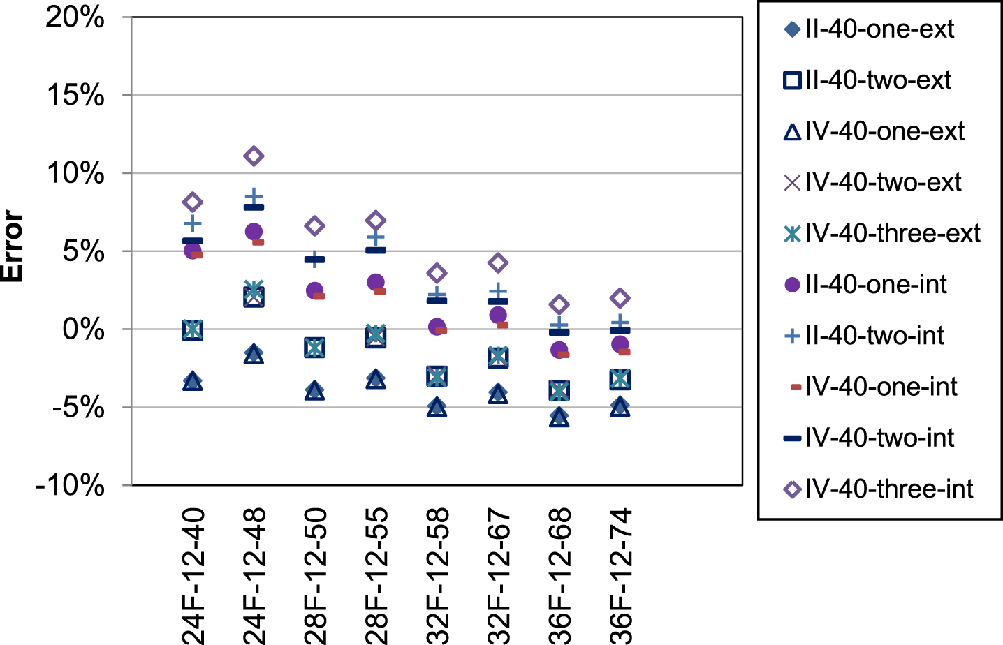
Error% between LRFD- and FE-SCFs (Type II and IV bridges, skew angle = 40°).
In this paper, the lateral distributions of live load moment in 160 NEXT beam simply-supported bridges are examined through simplified FE analyses by a comprehensive parametric study. Various beam sections and span lengths were explored. Five different skew angles (i.e., 0° to 40° with 10° intervals) were examined to identify the skew effects on the live load distribution in simply supported skewed NEXT beam bridges. Percent errors were computed between the LRFD - and FE-SCFs. Based on the research findings in this paper, the following conclusions can be made: The LRFD-SCFs governed the FE-SCFs when the skew angle ≤30°, indicating the LRFD-SCFs are conservative in this case. When the skew angle is 40°, some FE-SCFs exceeded the LRFD-SCFs by up to 2.20% and 5.65% for bridges with 2438 mm and 3658 mm wide NEXT beams, respectively. In this case, using LRFD-SCFs can lead to an unsafe design. It is recommended the LRFD-SCFs be used for the NEXT beam bridges with a skew angle ≤30°. For larger skew angles (i.e., 30°<skew angle ≤40°), it is suggested the LRFD-SCFs be conservatively increased by 6% to achieve sufficient safety margins for skewed NEXT beam bridges.
The NEXT beams have emerged as a promising bridge technique offering speedy construction, excellent durability, and minimal maintenance. Since NEXT beam bridges are new to practicing bridge engineers, research findings from this study narrow the gap between the innovative NEXT beam technology and bridge practitioners, providing meaningful guidance on the analyses and design of skewed NEXT beam bridges. This study could be a relevant source for the future update of the PCI design guidelines for NEXT beams and the AASHTO LRFD Bridge Design Specifications.