
Abstract
Development of multiple structural systems for bridges is useful in the design of new bridges and rehabilitation of existing bridges. This paper briefly presents some existing bridges with multiple structural systems and succinctly discusses design ideas for bridges with such systems. As an example of a bridge with multiple structural systems, the paper presents the reconstruction of a pedestrian suspension bridge in the City of Trilj, Croatia. The new bridge’s load-bearing structure is composed of several structural systems. Namely, the reconstructed bridge is a combination of suspension, cable-stayed and stress-ribbon bridge, which is laterally restrained with horizontal tensioned ropes. Numerical analysis was conducted on the renovated bridge. The results have shown an acceptable levels of stresses and deflections verifying the structural safety of the restored bridge. It is believed that this example of the bridge renovation may be useful in the design of new and strengthening of existing similar bridges.
Introduction
The load-bearing structural systems have been developed over time to different levels of complexity. The simple beam system (tree trunk laid across an obstacle) and the arched system (stone arch over an obstacle) date back to the beginnings of human civilization [1]. These load-bearing systems which are primarily subjected to bending (beams) and mainly to compression (arches), are subsequently upgraded with elements that are primarily subjected to compression (pylons) and tension (suspenders, hangers). Load-bearing structures subjected to tension, compression and bending are still today the main load-bearing structural systems that have been improved over time in accordance with the development of new materials and building construction technologies.
The main load-bearing system of a bridge refers to a type of span structure. The classical bridge types are: beam (slab), arch, frame, suspension, cable-stayed, stress-ribbon and their variants. The optimal load-bearing system of a bridge is mainly related to span length, construction material, purpose, foundation conditions, construction technology, etc. Throughout history and today, bridges need to meet aesthetic requirements. This is particularly true for modern bridges where appearance is crucial. In this context, unusual, attractive and sometimes exotic solutions of the load-bearing structure are used.
For most today’s bridges, only one type of load-bearing structures is used in their main span. However, the bridges with the combined load-bearing systems have been designed and built recently [2]. Some of the reasons for such solutions are: greater rationality, easier and faster construction, achieving longer span, more attractive appearance, development of bridge construction, etc. In such solutions, all the positive characteristics of each load-bearing structure are applied, as well as the properties of the used material. At the same time, the different load-bearing structures have been combined [3], which was unusual in classical bridge construction (i.e. arch and cable-stayed structures/bridges).
In addition to the new bridges construction, the combination of multiple structural systems have been increasingly used in the strengthening and reconstruction of the existing bridges [4]. Such an approach is considered acceptable because it provides a variety of solutions and milder requirements for the aesthetic appearance of the bridge.
The development and application of the multiple structural systems, the improvement of existing building materials and development of new ones, as well as their optimal application in load-bearing structures will help further development of bridges and building structures in general.
In this paper, some of the recent and most popular existing bridges with multiple structural systems are summarized in Section 2. Then, some other possible multiple structural systems for bridges are briefly described in Section 3. In Section 4, the reconstruction of a pedestrian suspension bridge in Trilj is presented, where the combination of several different load-bearing structures was used. Finally, the main conclusions of the study are presented.
Some bridges with multiple structural systems
Some famous bridges with multiple bearing systems are briefly described below.
The Brooklyn bridge with a main span of 486.3 m was constructed 1883 [5], and is one of the first bridges with a combination of suspension and cable-stayed bridge (Fig. 1). The Saint-Ilpize bridge with span of 70 m, designed by Arnodin and completed in 1879, is also one of suspension bridges with stay cables near pylons (Fig. 2).
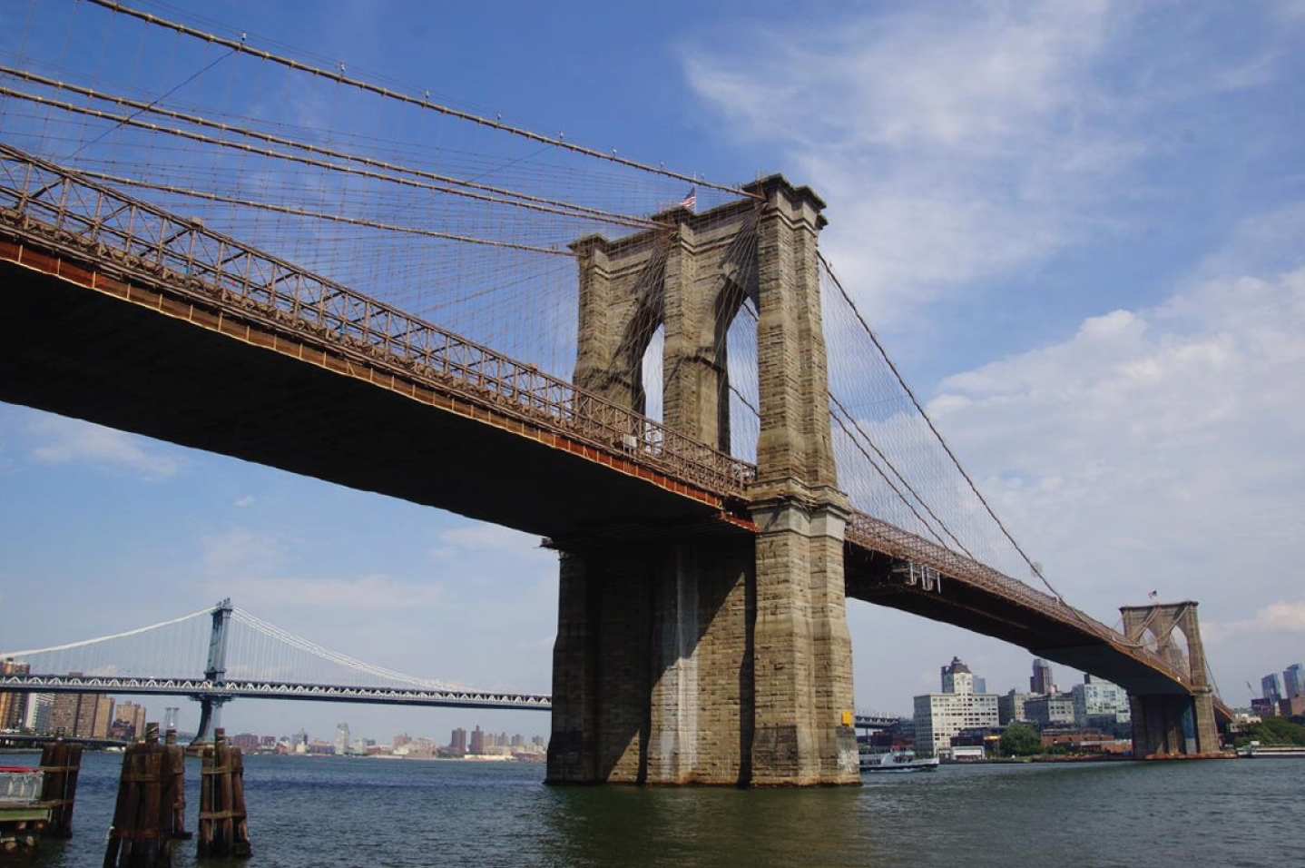
Brooklyn bridge in New York City [6].
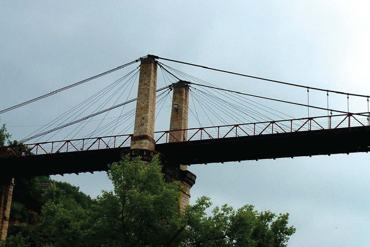
Saint-Ilpize bridge in Saint-Ilpize France [7].
The Sidi M’Cid suspension bridge in Algeria, with main span of 160 m, was also designed by Amodin in 1908 [8]. As part of the renovation, the bridge was strengthened with stay cables near the pylons and transformed into a mixed suspension cable-stayed bridge (Fig. 3). The Nagisa bridge in Japan (Fig. 4), completed in 2002, with the main span of 110.15 m is the first hybrid prestressed concrete cable-stayed and steel cable-suspended bridge in the world [10]. The prestressed concrete deck near to pylon is suspended by stay cables, and the steel deck in the middle of the span by hangers.
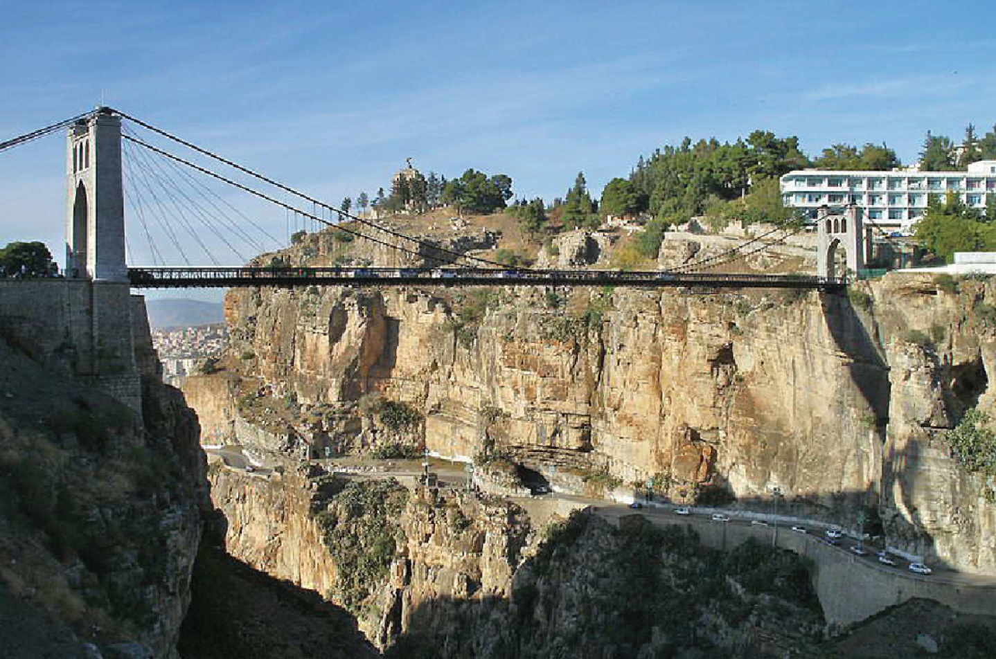
Sidi M’Cid bridge in Constantine, Algeria [9].
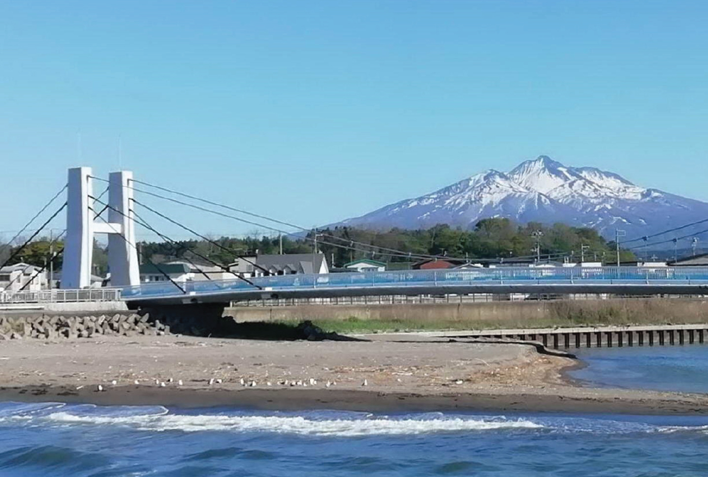
Nagisa bridge in Aomori Prefecture, Japan [10].
The strengthening of a suspension bridge in China was presented in [4]. The suspended concrete girder, with the main span of 65 m, was transformed after strengthening into the suspension and cable-stayed girder. The strengthened bridge has a significantly higher load-bearing capacity and safety, while stress amplitude of original cable system was greatly reduced. The Dongtiao bridge in China (Fig. 5) with main span of 228 m, finished in 2015, is a new type of bridge based on a spatial cable self-anchored suspension and cable-stayed cooperation structural system [2]. The Yavuz Sultan Selim bridge was constructed in 2016 (Fig. 6). With the main span of 1408 m, it is the longest cable-stayed suspension bridge today.
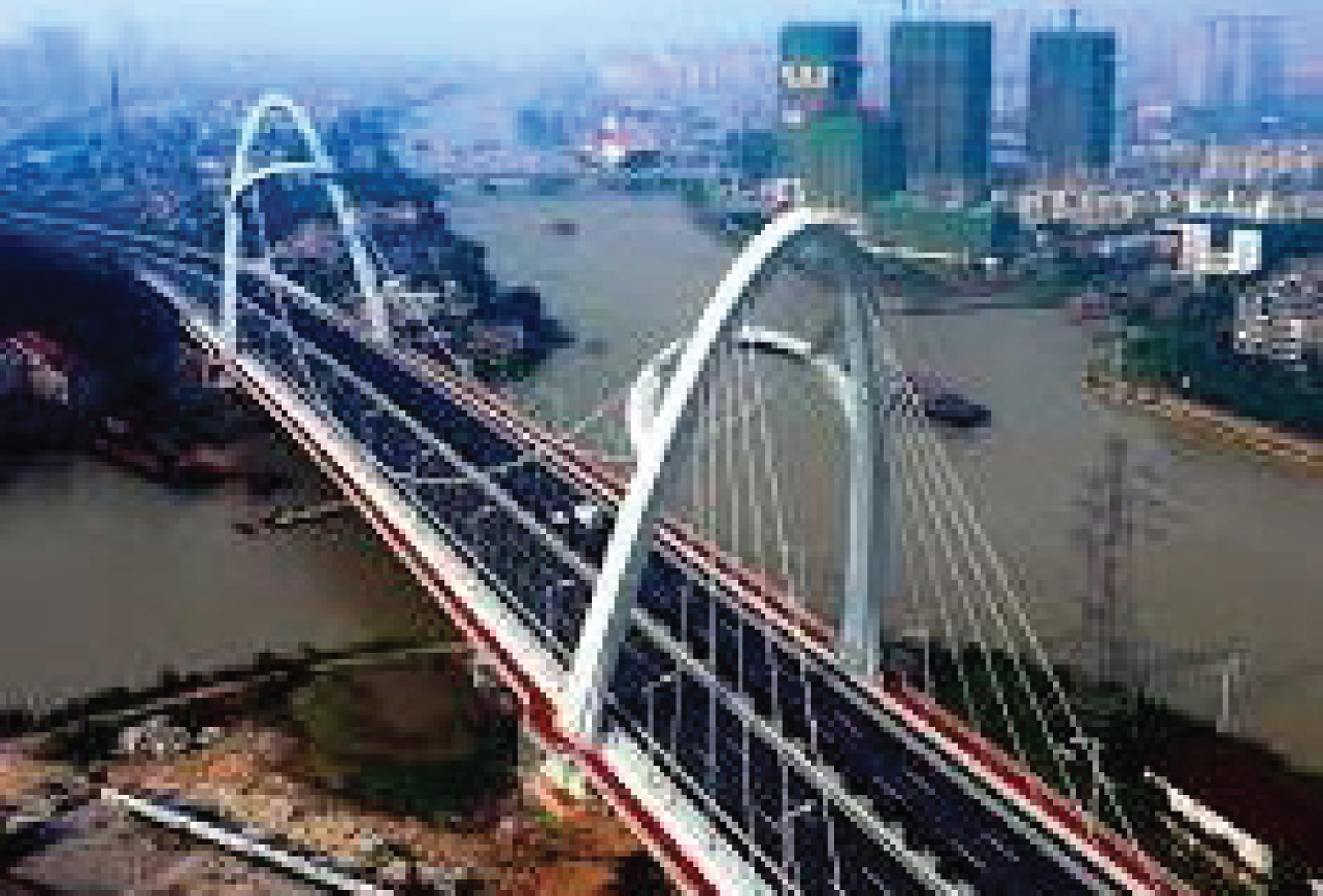
Dongtiao bridge in Huzhou, China [2].
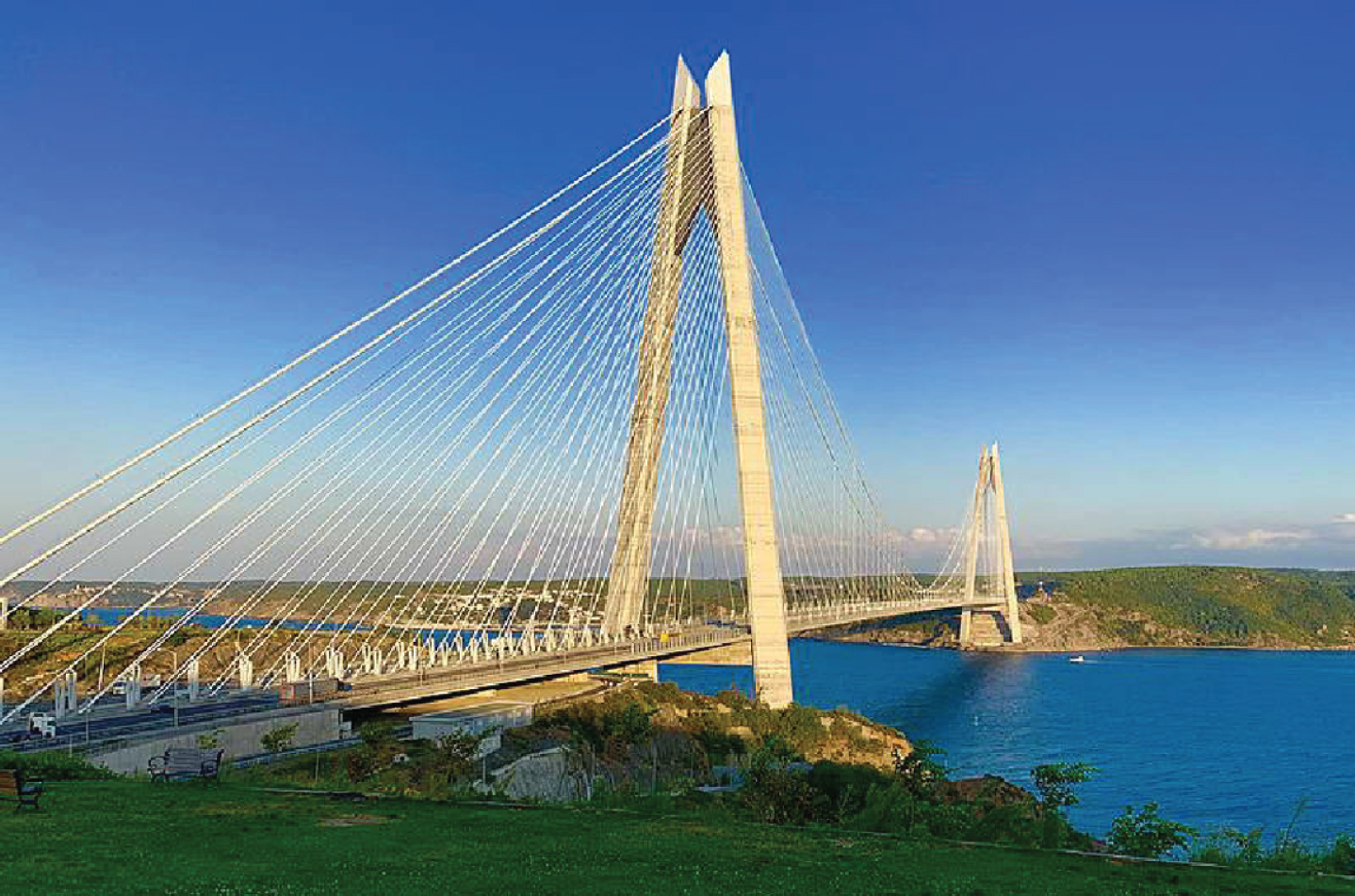
Yavuz Sultan Selim bridge in Istanbul, Turkey [11].
One of the proposed variants for the Gibraltar strait crossing (Fig. 7) was using combined suspension and cable-stayed bridge with extremely long spans [12]. Concept combination of suspension and cable-stayed structural system for extremely long span bridges can be also found in [13]. The Seri Saujana bridge is cable-stayed arch bridge in Malaysia (Fig. 8) with the span of 300 m was constructed in 2002, presenting the first bridge in the world with interaction of different structural systems [3]. This unique structure is a provoked combination of arches and classical cable-stayed bridge.
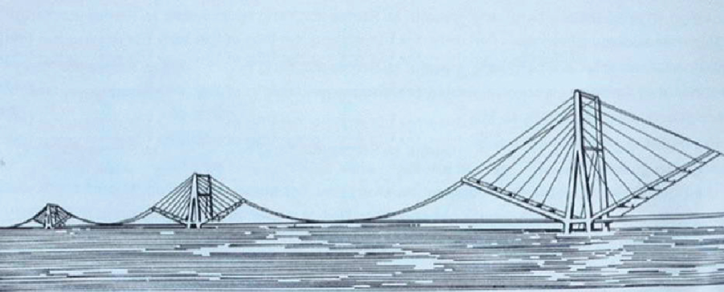
Concept bridge to cross Strait of Gibraltar [12].
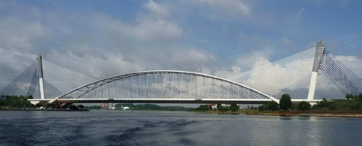
Seri Saujana bridge in Putrajaya, Malaysia [14].
These new generations of structural systems are beyond traditional structures, based on the state of the art. These bridges are substantial improvement in design, constructing, economy and durability. Some computational aspects of bridges with multiple structural systems can be found in [15, 16].
According to the solutions presented on the previous section, some variations of multiple structural systems for bridges are suggested in Fig. 9. These are only discussed as an idea for consideration and are not elaborated in details, wherein additional modifications and variations are possible. Their basic properties are briefly described below.
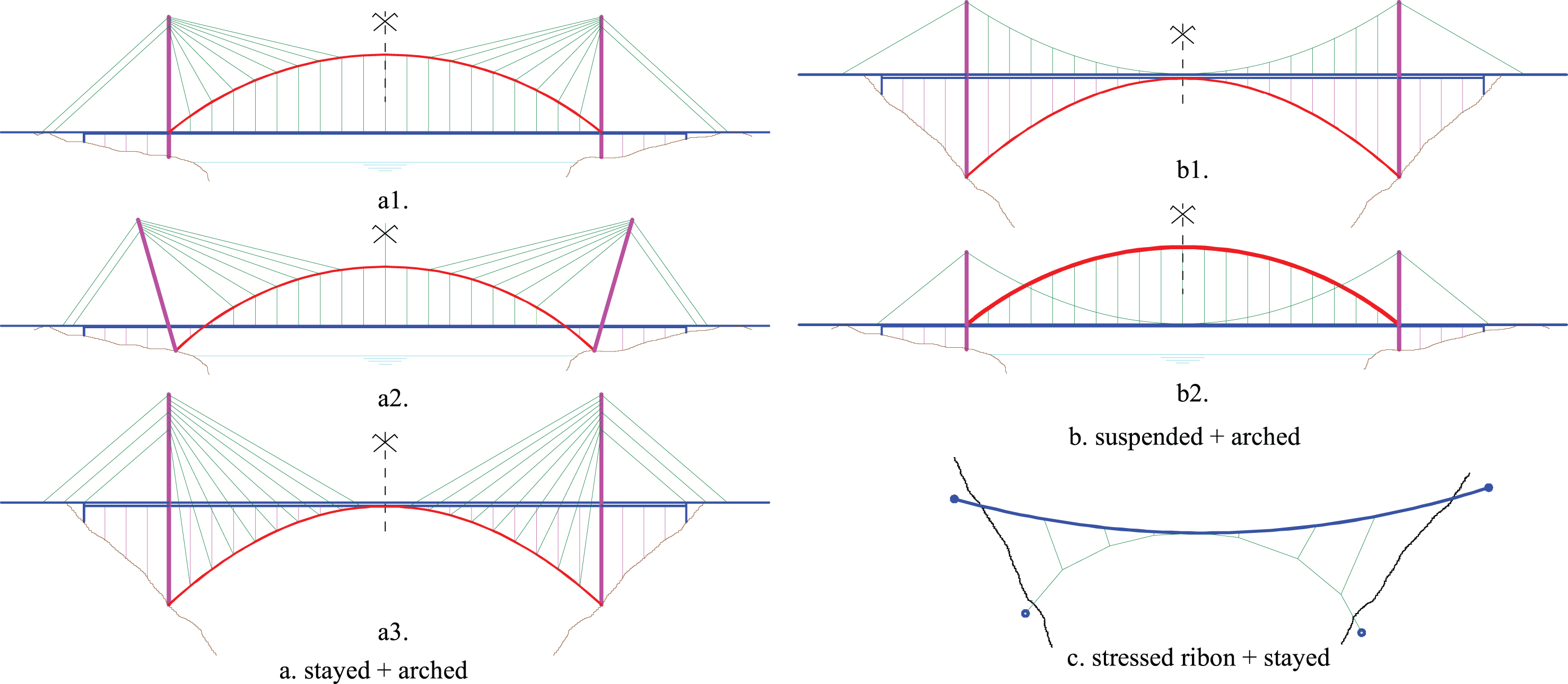
Schema of some possible multiple structural systems for bridges.
The load-bearing structure that combines arch and cable-stayed bridge is shown in Fig. 9a. Thus, the combination with the through arch bridge is shown in Fig. 9a.1, the half-through arch bridge in Fig. 9a.2 and the deck arch bridge in Fig. 9a.3, respectively. The provided solutions could be competitive for arch span of approximately 400–500 m. In relation to arch and cable-stayed bridges, the main advantages of such solutions are: reduction of arch, pylon and suspender dimensions, easier and faster bridge construction, and structure rationality. The use of different construction technologies and the possible aesthetic appearance of the bridge sometimes can be disadvantage of such solution. The solutions are particularly adapted to the easier arch construction, which is a very rational structure and demanding to build at the same time.
The load-bearing structure that combine arch and suspension bridge is shown in Fig. 9b. The combination with the deck arch bridge is shown in Fig. 9b.1, and the through arch bridge in Fig. 9b.2, respectively. The provided solutions could be competitive for arch span of approximately 500–600 m. In relation to arch and suspension bridges, the main advantages of such solutions are: reduction of the dimensions of arch, main suspension cables and pylons, easier and faster bridge construction, and structure rationality. The use of different construction technologies and the possible aesthetic appearance of the bridge, can also be disadvantage of such solution.
The stress-ribbon bridges are rational structures and aesthetically favourable for pedestrian bridge. The main disadvantages of such bridges are deformability and vibration under pedestrian load and wind. The combination of the stress-ribbon bridge and stay cables below the deck is shown in Fig. 9c. The stay cables reduce the vertical and lateral displacements of the bridge deck under pedestrians load and wind.
The realisation of bridges with the combination of suspension, cable-stayed and arch structure elements can be expected in the near future. The primary purpose of this article is not a theoretical analysis of multiple structural systems for bridges, which will no longer be discussed here, but an example of one such solution which was applied in practice and presented below.
The state of the bridge before the reconstruction
The Trilj Bridge (Fig. 10) is crossing the Cetina river in the city of Trilj, which is located approximately 20 km northeast from Split (Croatia). This pedestrian suspension bridge, with span of 114.46 m and useable width of 1.2 m (Fig. 11), was constructed in 1967. The bridge is straight in plan, with a concave and symmetrical vertical curve. At the middle of the span, the bridge deck was lowered by 3.14 m in the relation to its level at the pylon.
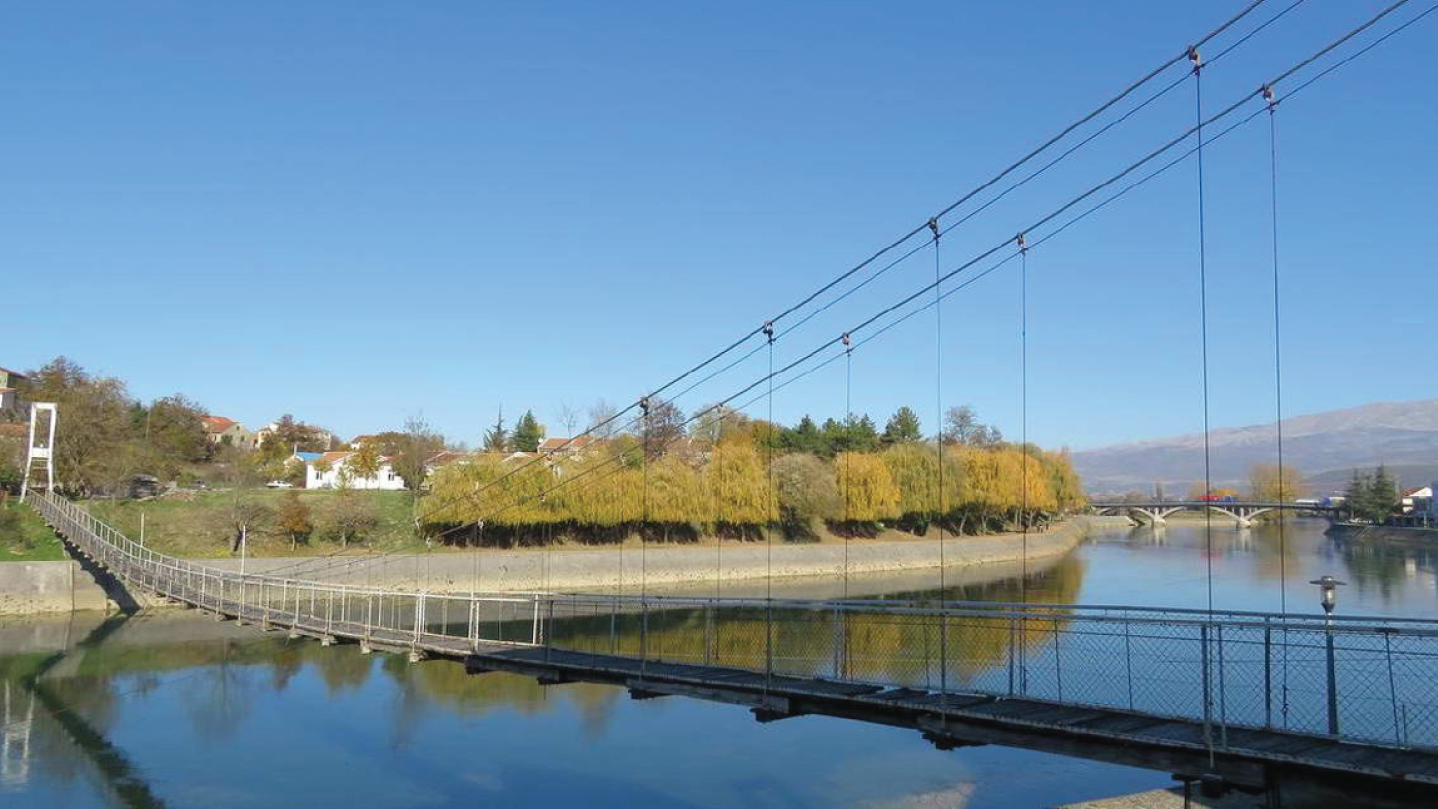
Global view of the Trilj Bridge.
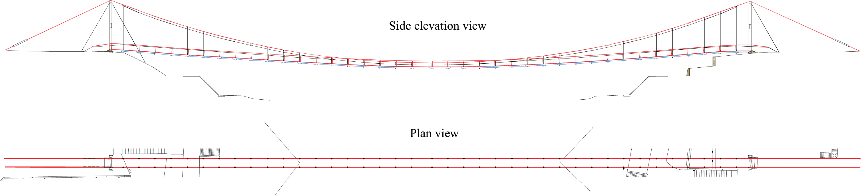
Drawing plans of the Trilj Bridge before the reconstruction.
The main suspension cable was a steel rope of 30 mm in diameter, with the sag of 11.2 m and the uplift of 0.75 m above the deck at the mid-span. The pylons were made from reinforced concrete, with longitudinal hinges at the bottom. The bridge had 76 vertical hangers, with 18 mm in diameter, on the longitudinal spacing of 2.85 m (Fig. 11 - Side elevation view). The hangers were attached in a simple way to the main suspension cable and bridge deck. The wooden deck was supported by longitudinal wooden girders, which were supported by cross wooden beams at the location of the hangers. All parts of the deck structure were connected in a simple way. Two side ropes were used for horizontal lateral stabilization of the bridge. The side ropes were attached to the longitudinal wooden beams in a simple way at the distance of 20 m from the middle of bridge (Fig. 11 - Plan view). The longitudinal tensile force in the bridge deck was transformed by the rope between the connections of the side ropes to cross-beams. Two inclined ropes, 10 mm in diameter, stabilized the pylon tops in the longitudinal direction. The bridge had a provisional fence.
Due to age and some inadequate design solutions, the bridge was in an unacceptable condition in terms of stability, functionality and aesthetic appearance. The state of some of bridge elements will be briefly commented below.
The main suspension cables were in relatively good state, but somewhere corroded and in direct contact with soil at the anchorage zone. The pylons were slightly inclined towards the river, with the corrosion of reinforcement at some places. Some ropes for longitudinal stabilization of the pylon top were cut. The hangers were significantly corroded and inadequately connected to the suspended cable and wooden cross-beams. All parts of the wooden deck were worn out, and some were rotten. The side ropes for bridge horizontal stabilization were unjointed and corroded. Their anchoring blocks were small in size, vertically inclined and inappropriately designed. The bridge had large vibrations and deflections caused by a single pedestrian crossing, and significant lateral deflections under light wind. The bridge approaches were unsightly. In general, the bridge was totally neglected and almost in a catastrophic state, with a real danger of collapsing. The impression of the bridge state before the reconstruction can be seen in Fig. 12.
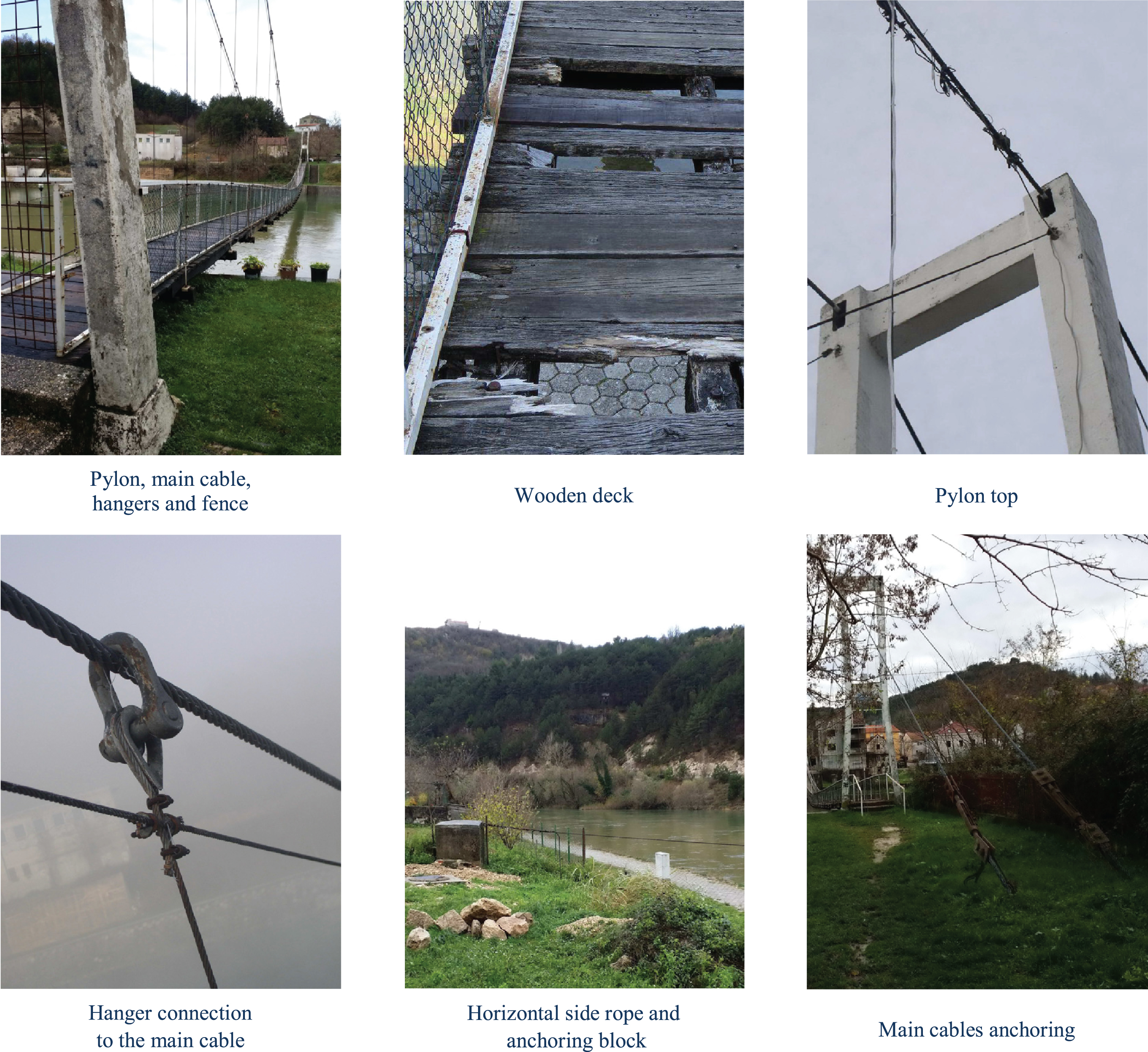
Some bridge parts before the reconstruction.
The main cables and pylons were kept in original form, but were renovated. The other bridge parts were replaced with new ones (Fig. 13). The emphasis was not on presenting the detailed repair works, so it was briefly described. More details can be found in [17].
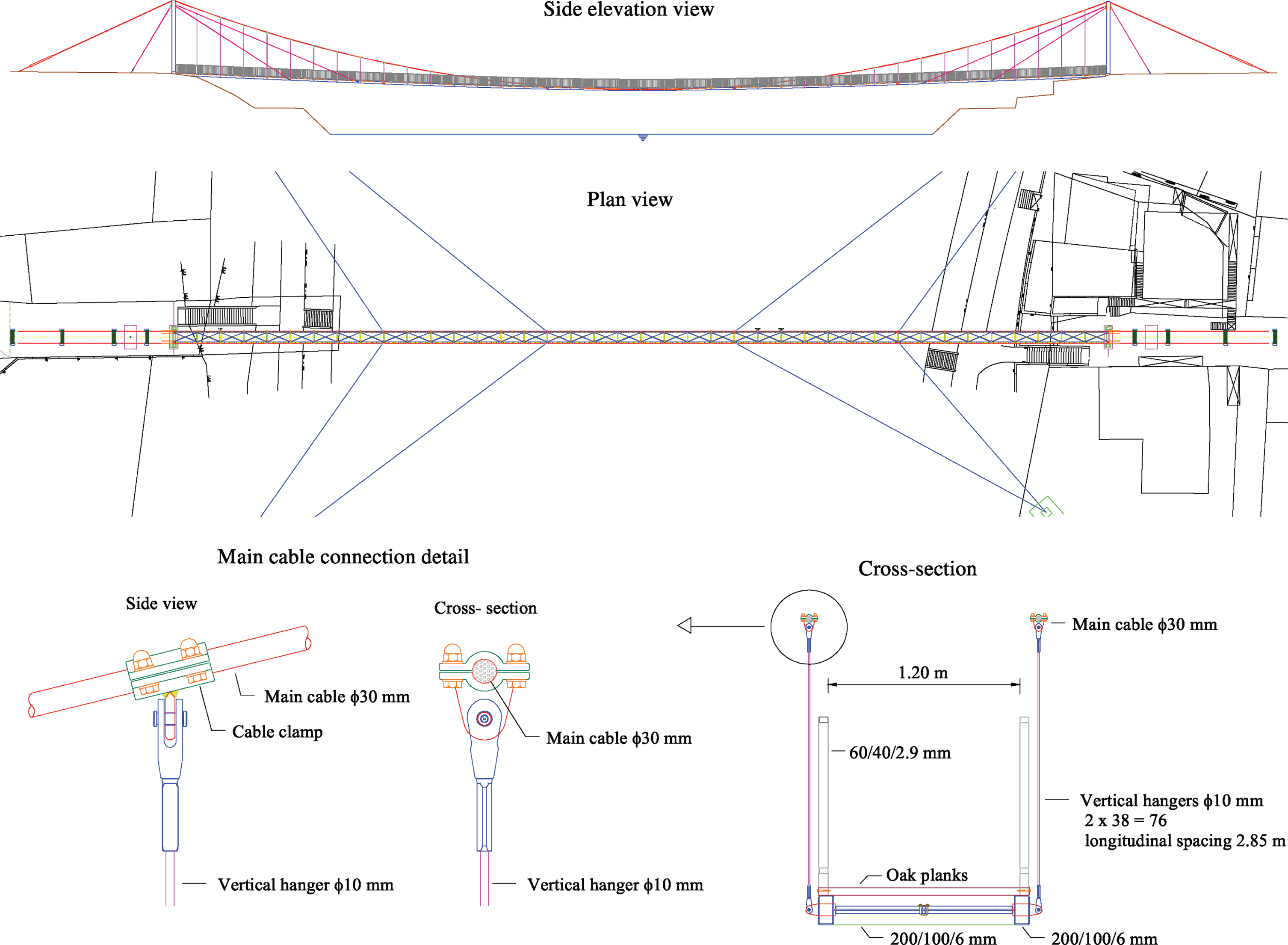
Drawing plans of the Trilj Bridge after the reconstruction.
The visual inspection of the main rope condition was conducted. Since there were no abrasions, significant corrosion, broken wires, pitting, etc. of the main cable, the other non-destructive inspections were not necessary. The corrosion of the galvanized steel ropes was almost imperceptible and the future annual monitoring will be continued. The surface corrosion was found on the rope only at the anchorage zone. The old anchorage blocks in soil was replaced with a new concrete massive block with appropriate external protection of the rope above the concrete slab (Fig. 14.b). Although the corrosion of the ropes was almost imperceptible, for the case of a corroded wire, the influence of a single corroded wire to overall stiffness of entire rope is insignificant, as the highest stress calculated in the main rope was below 50% of the rope capacity. The steel rope had been galvanized previously, and now additionally protected from corrosion by zinc-based paint. The pylons were also renovated by a new concrete cover and painted.
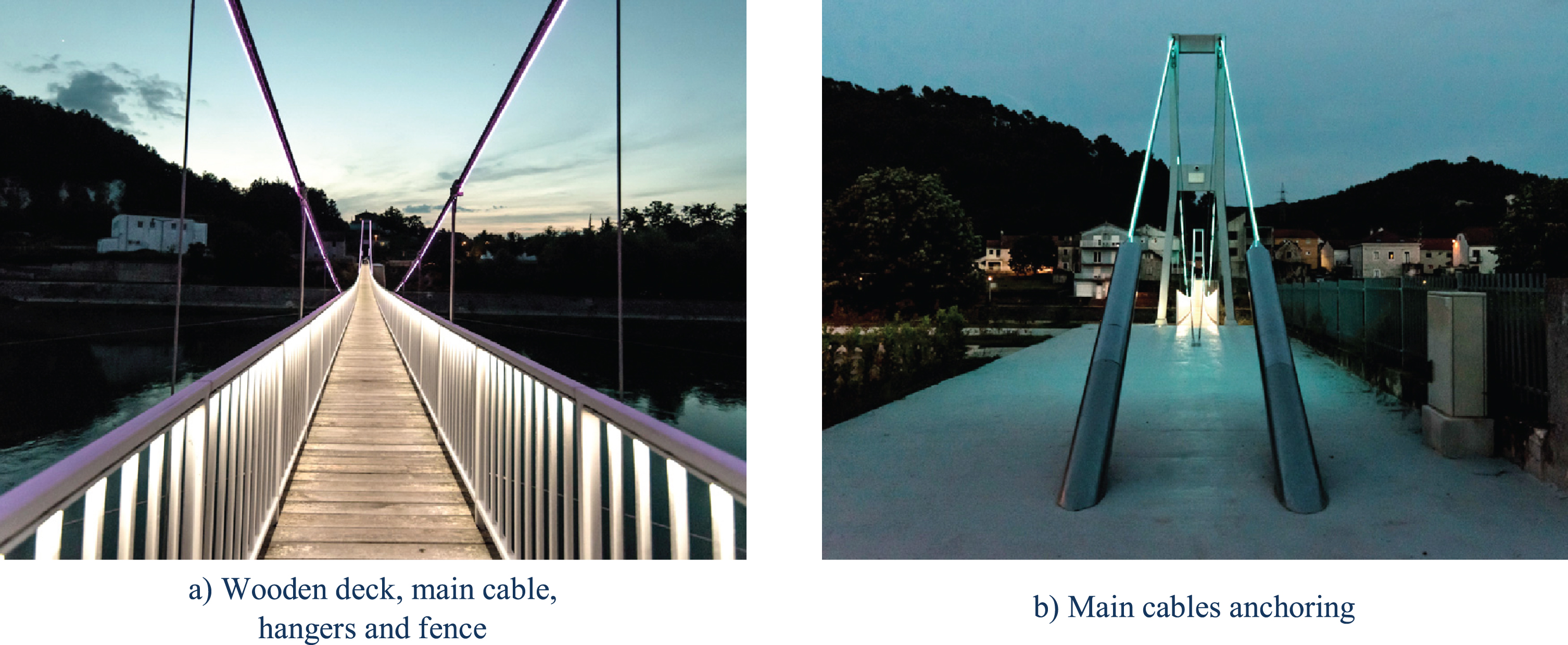
Some bridge parts after the reconstruction.
The level of bridge deck was lowered at the abutments and uplifted to the level of main cable at the mid-span (the cable and deck were connected) (Fig. 13 - Side elevation view). This resulted in smaller longitudinal slope of the pedestrian corridor, more comfortable crossing and greater bridge stiffness. The longitudinal and transverse wooden beams were replaced with the steel beams of the rectangular hollow section (Fig. 13 - Cross section). They were welded and formed a stiff frame in the horizontal plane, additionally stiffened by cross tension bracing. The longitudinal beams were anchored into a new massive concrete slab behind the pylons, and slightly prestressed. Therefore, the bridge deck was significantly stiffened, the tensile stress of the main suspension cable was reduced, and the load-bearing capacity and safety of the bridge were increased. The walkway on the bridge was made of thermo-treated oak planks.
The new steel bridge deck was suspended on main cables by new modern hangers without slippage (Fig. 13 - Detail). Further, the deck was stayed by ropes near the pylons. This decreased tensile stresses in suspended cables and increased the bridge safety, as well as reduced the vertical deflection of the bridge deck. The bridge deck was restrained horizontally in four places with side ropes, in order to increase the bridge lateral stiffness (Fig. 13 - Plan view). The bridge safety was increased and the lateral displacements under the wind were reduced. The side ropes were anchored in new massive concrete blocks.
The new bridge fence is significantly stronger, safer and prettier than the previous one Fig 14.a). The side view of the reconstructed bridge is shown in Fig. 15. The handrail and main cables lighting contributed to pleasant pedestrian crossing and attractive night view of the bridge (Fig. 16).
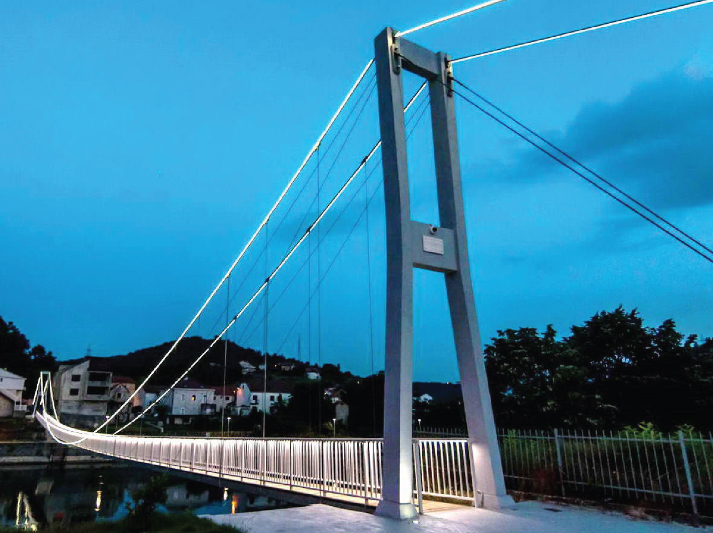
Side view of the reconstructed Trilj Bridge.
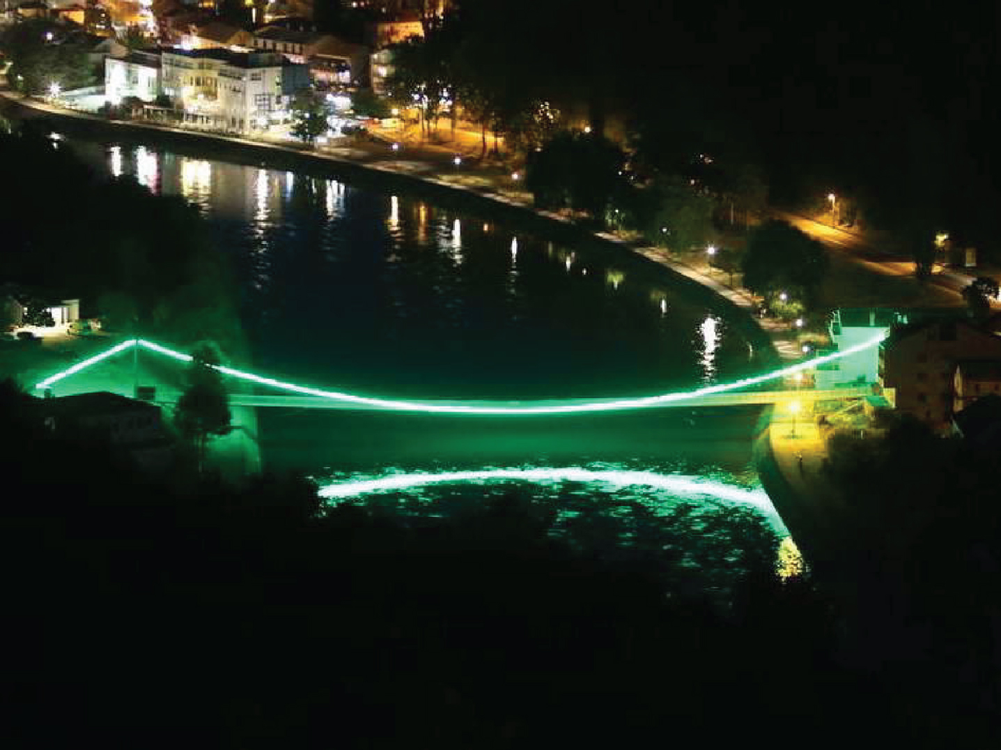
Aerial view of the reconstructed Trilj Bridge.
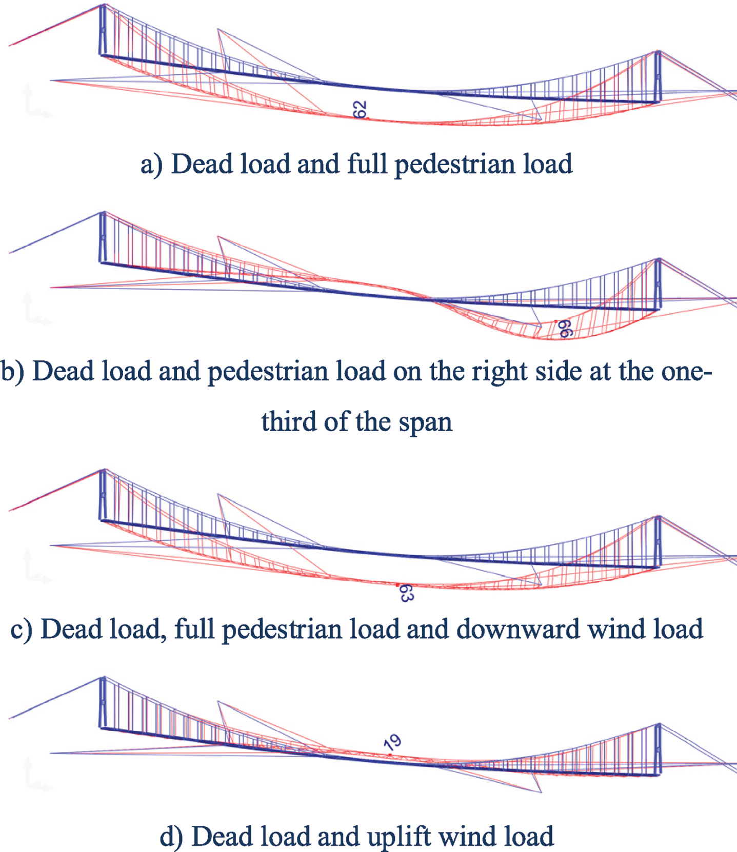
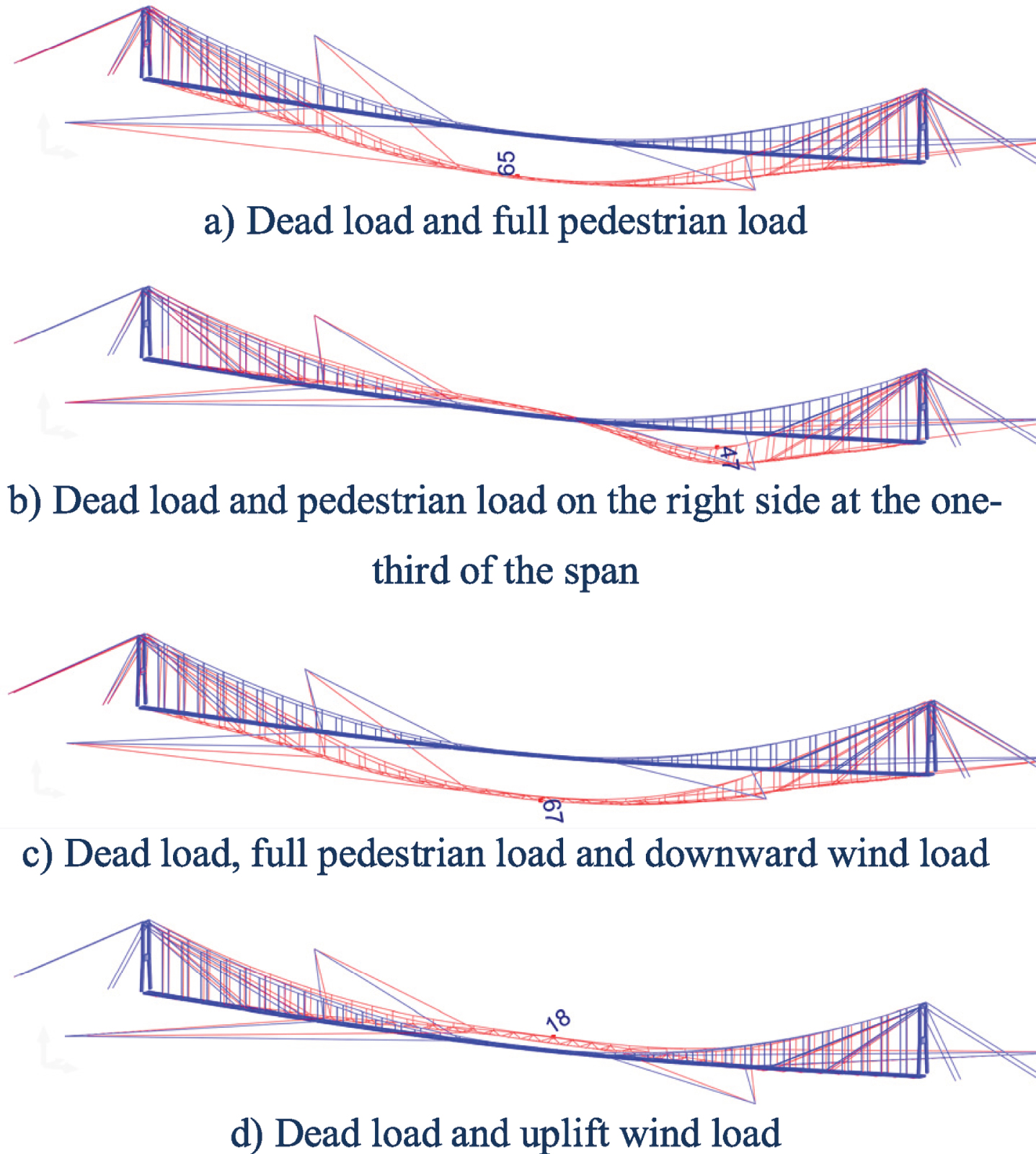
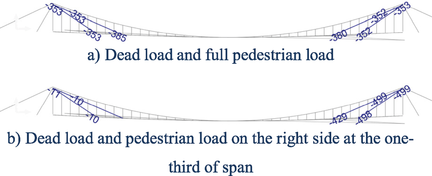
In structural view, the old suspension bridge was transformed into a combination of suspension, cable-stayed and stress-ribbon bridge, and additionally restrained with the side ropes. A previously developed numerical model for the analysis of the structures with cables was used [18]. The software can simulate the non-linear effects of the large displacements, including cable tensioning. The new bridge was designed and checked according to Eurocodes. The design of the steel members was performed according to Eurocode 3 [19], while the design of the concrete elements was performed according to Eurocode 2 [20]. Numerical analysis was conducted only for the new reconstructed bridge because it had a new geometry and a new structural system and it was not suitable for a comparison with the old one. Only some results are presented and discussed in this paper: the displacement and tensile stresses, as design criteria. The analysis were conducted for all relevant load cases, such as: dead load, full pedestrian load, pedestrian load on the right side at the one-third of the span, downward wind load and uplift wind load. Two types of structural system were analysed and compared: the system without stay-cables and the system with stay-cables. Vertical displacement of the bridge without the stay-cables are shown in Fig. 17 and the corresponding displacement for the bridge with the stay-cables are shown in Fig. 18. The red lines denotes the deformed shape of bridge and it was scaled. As it was expected, the stay-cables stiffened the deck near the pylons resulting with smaller deflections at the sides of the span. The deflection at the mid-span were about to same for both system under full pedestrian load and wind load. Some tensile stresses of the main suspension cables, backstays and lateral suspenders of the bridge are presented in Fig. 19-20. The stay-cables lowered the stresses in the main suspension cables. The tensile stresses of the stay-cables are shown in Fig. 21 and the stresses of the longitudinal steel beams are shown in Fig. 22. All maximum stresses and deflections were below the design criteria. The highest stress computed in the main rope before the reconstruction was 696 MPa (shown in Fig. 19.a), while the highest stress computed in the main rope after the reconstruction was 635 MPa (shown in Fig. 20.a), which is below 50% of the member capacity.
Some vertical displacement of the bridge without stay-cables (mm).
Some vertical displacement of the bridge with stay-cables (mm).
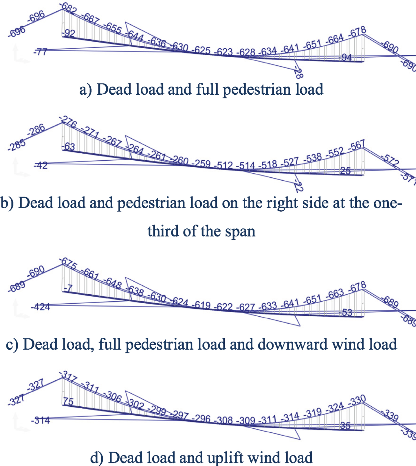
Some tensile stresses of the main suspension cables, backstays and lateral suspenders of the bridge without stay-cables (MPa).
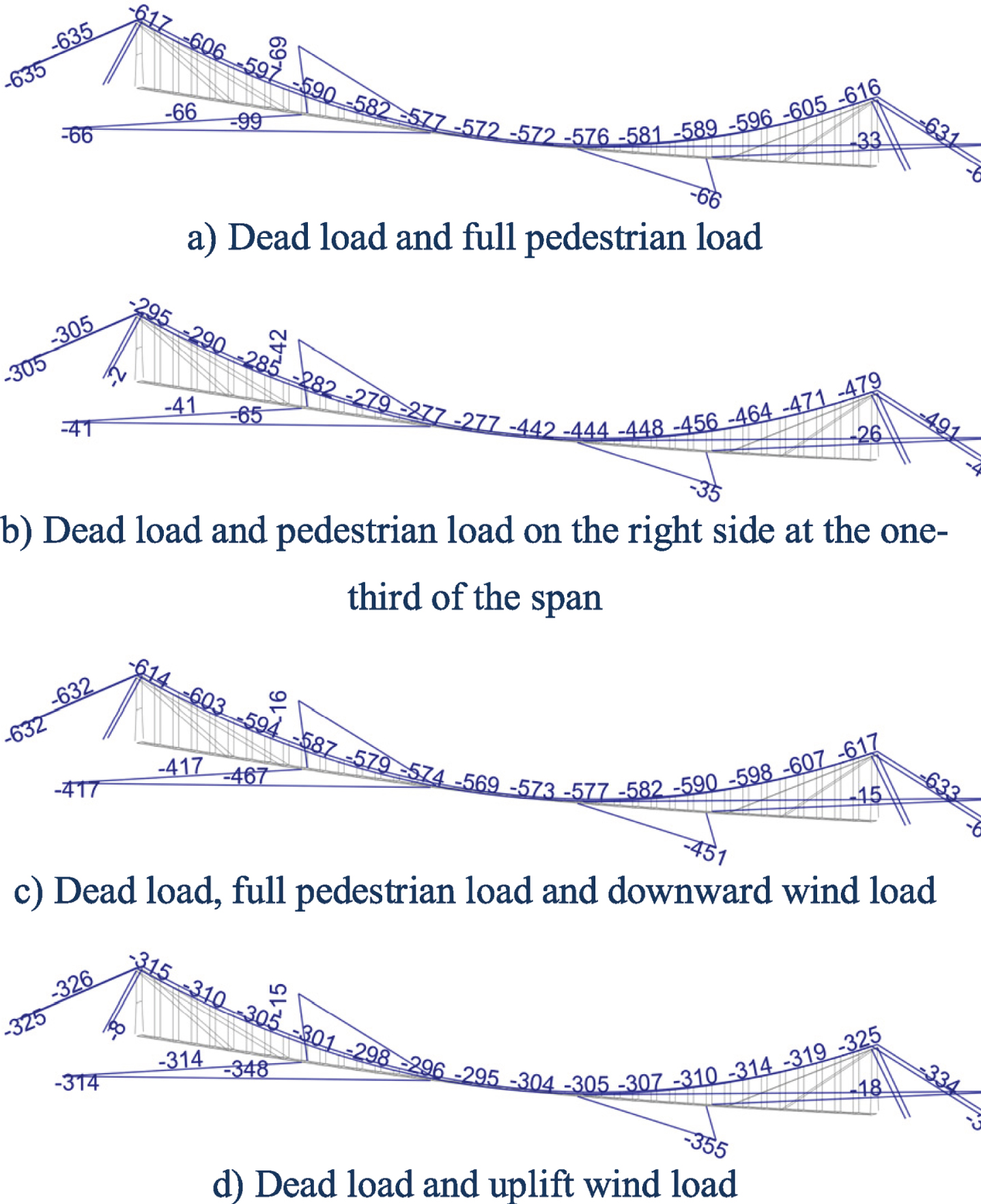
Some tensile stresses of the main suspension cables, backstays and lateral suspenders of the bridge with stay-cables (MPa).
Some tensile stresses of the stay-cables (MPa).
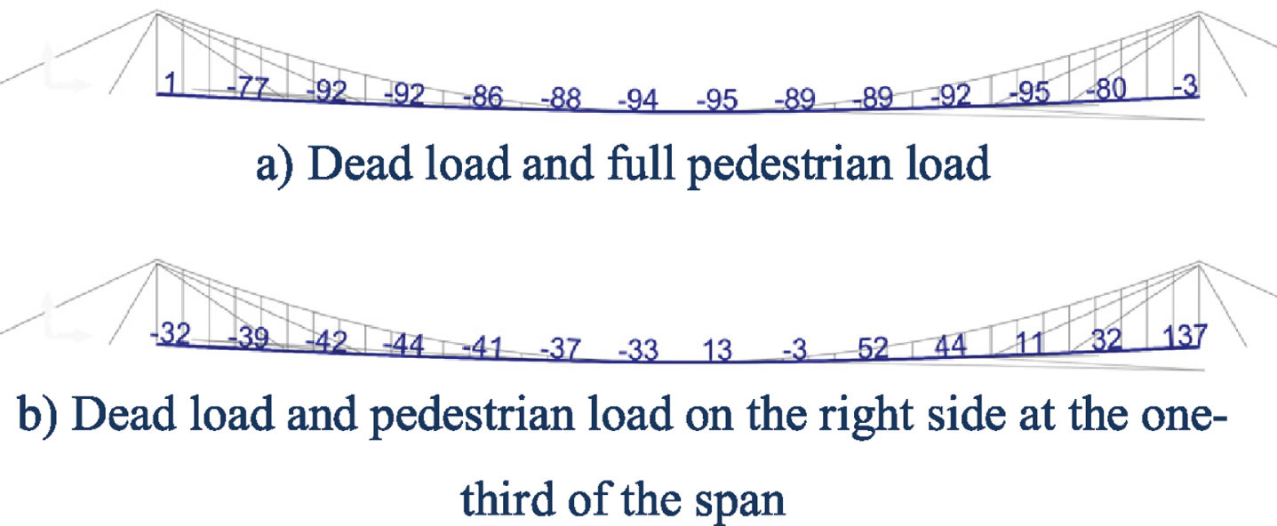
Some stresses of the longitudinal steel beams (MPa).
The multiple structural systems will undoubtedly find wide application in the design of new bridges. In combination with adequate building materials for individual structural elements, such structural systems will enable the achievement of larger spans, easier construction and greater bridge rationality. In terms of aesthetic design, such solutions will be increasingly acceptable, interesting and attractive. In this regard, the creativity and imagination of structural engineers and architects will play a major role in the development and application of such solutions.
Using the new load-bearing structures and modern building materials, the multiple structural systems will be widely used in the strengthening and reconstruction of the existing bridges. The efficiency of such solution is illustrated by the example of the reconstruction of the existing ruined suspension pedestrian bridge in the city of Trilj, Croatia.
The bridge was reconstructed by: (i) renovation of the main suspension cables and pylons, (ii) replacing the existing wooden deck girder with the new steel tensioned deck girder (the element of stress-ribbon bridge), (iii) supporting the deck beam with new stay cables anchored to the pylons (the element of cable-stayed bridge), (iv) lateral stabilisation of the deck with tensioned horizontal ropes, and (v) uplifting deck level in the mid-span and lowering the deck at the pylons. Other improved solutions were also made, such as bridge lighting, bridge approaches, etc.
Numerical analysis was conducted on the new bridge structure after the renovation. The reconstructed bridge has significantly improved safety and serviceability offering a far better aesthetic appearance. “The ugly duckling” has been transformed into a decorative symbol of a small city of Trilj. The intention is that this bridge reconstruction example serves as a guide for similar and new innovative solutions used for strengthening of the existing and design of new bridges.
Footnotes
Acknowledgments
This work was supported by funds from the Ministry of Science, Education and Sport of Croatia, as well as the city administration of Trilj. The authors appreciate their financial support.
.jpg)