
Abstract
Fuzzy tissue-like P systems (FTPS), as a new variant of tissue-like P systems (TPS), is proposed in this paper. FTPS inherits the advantages of TPS and has the ability of dealing with incomplete and uncertain information. FTPS is very suitable to model the causal relationship between a fault and its protective devices in power systems. A forward reasoning algorithm based on FTPS is developed, and then the corresponding fault diagnosis model is discussed. In order to evaluate the availability and effectiveness of the proposed fault diagnosis model, three case studies of fault diagnosis of a transmission system are discussed and analyzed, including simple fault, complex faults and multiple faults with uncertain status information. The results of case studies demonstrate that FTPS can be used to diagnose faulty sections in power systems accurately and effectively.
Introduction
Fault diagnosis of power systems is such a task that identifies the faulty system elements according to the operating signals of protective relays (PRs) and circuit breakers (CBs). Usually, supervisory control and data acquisition (SCADA) system is equipped together with electric power systems. The operating signals are retrieved from SCADA system. With gradually scale extension and increasingly structure complexity of power systems, system elements have been become more and more complex. When a fault occurs, dispatchers need to isolate the influenced branches quickly and accurately, and take the necessary measures to restore the normal power supply as soon as possible. At this time, alarm messages from SCADA system can be immediately transmitted to the dispatch center system to provide the data source for fault diagnosis. However, these messages are often incomplete and uncertain, especially in complex and multiple fault situations. Therefore, fault diagnosis of power systems becomes an important and difficult task in the situation in which there are the failures of protective devices and multiple faults with incomplete and uncertain fault messages.
In recent decades, artificial intelligence methods [1, 9, 10, 16, 22, 24] have been widely applied to engineering problems, for example, fault diagnosis of power systems. Expert system (ES) is a mature approach for fault diagnosis of power systems [11, 14]. However, it has a slow inference speed and poor tolerance ability. With their attractive features, artificial neural networks (ANN) are an adaptive system that changes its structure based on external and internal information that flows through the network during the learning phase, and it has the advantages of good tolerance and strong learning ability [2, 25, 25]. However, the disadvantages of ANN are the need for numerous samples and poor generally interpreting ability. The fault diagnosis of power systems can be also formulated as an optimization problem. Some optimization techniques (for example, GAs and HBMO) were employed to solve the optimization problem [12, 14]. Since the outage area must be identified initially, the loss of a boundary CB alarm may lead to the failure of such methods. In fault diagnosis of power systems, it is a challenging problem how to deal with the uncertainty. Some fuzzy techniques have been applied to discuss the challenging problem, such as fuzzy logic (FL), fuzzy relations (FR) and fuzzy digraph model (FDM). Chin [6] combined classical fuzzy logic with cause-effect network to deal with the uncertainty in fault diagnosis of power systems. Cho and Park [7] presented a fault method based on fuzzy relations, where the relationship between the operated protective devices and the fault section candidates was modeled and reasoned by fuzzy matrix. In Chen [3], fuzzy digraph model was used to propose a fault diagnosis method. In these methods, classical fuzzy logic and reasoning mechanism were used to express and handle the uncertainty in fault diagnosis of power systems, however, their ability for the fault diagnosis problems still needs to be studied further.
Membrane computing (MC) is a class of distributed parallel computing models, known as P systems or membrane systems, inspired from the structure and functioning of living cell as well as from the cooperation of cells in tissues, organs, and populations of cells [18, 19]. In past years, a various of variants of P systems were proposed and applied to different real-world problems, for example [21, 23, 33]. P systems have three main forms: cell-like P systems (CPS), tissue-like P systems (TPS) and spiking neural P systems (SNPS). TPS can be regarded as a net of cells, which deals with the objects and communicates them along the channels given in advance [8]. However, there exists a limitation in application: TPS is unable to deal with uncertain information. Thus, a new variant of TPS is proposed in this paper, called fuzzy tissue-like P systems (FTPS). FTPS not only inherits the advantages of TPS but also has the ability of processing incomplete and uncertain information. In this work, main motivation of proposing FTPS is to develop a novel fault diagnosis model for power systems. The causal relationship between a fault and its protective devices in power systems can be modeled by FTPS, and a forward reasoning algorithm for fault diagnosis is developed according to the mechanism of FTPS.
In recent years, fuzzy spiking neural P systems (FSNPS), as a variant of SNPS [13], have been developed by Peng et al. [20, 29], and have been applied to discuss the fault diagnosis problem of power systems, for example [27, 28, 30, 31]. FTPS and FSNPS are the distributed parallel computing models and can be the effective graphical modeling tools that are suitable to model and analyze fault diagnosis problems of power systems. However, the differences between FTPS and FSNPS can be summarized as follows.
In FSNPS, a fault diagnosis problem can be described by a set of fuzzy production rules, and then rule neurons and proposition neurons are used to express the fuzzy rules and the fuzzy proposition in them respectively. FTPS is used to model the causal relationships between faulty sections and their protective devices. The forward reasoning algorithm of FTPS is developed according to the communication rules with weight in cells, while in FSNPS fuzzy reasoning algorithm is based on the firing mechanism of neurons.
In summary, main contribution of this paper stays on proposed FTPS first time and developing a novel tool for fault diagnosis of power systems by modeling the causal relationships between faulty sections and their protective devices.
The rest of this paper is organized as follows. FTPS is introduced in Section 2. Section 3 discusses a modeling method based on FTPS for fault diagnosis problem and a forward reasoning algorithm. The case studies of power transmission networks are provided in Section 4. Conclusions are finally drawn in Section 5.
FTPS
Tissue-like P systems (TPS) are a kind variant of P systems, which are the distributed parallel computing models [8, 19]. However, there is a limitation in TPS: it can not process uncertain information. In this study, TPS is extended to propose a variant, called fuzzy tissue-like P system (FTPS), which inherits the advantages of TPS and has the ability to deal with the uncertainty. Moreover, FTPS is used in fault diagnosis of power transmission networks. We first review the definition of TPS briefly, and then describe in detail the FTPS.
(a) A cell in FTPS, and (b) the simplified graphical symbol.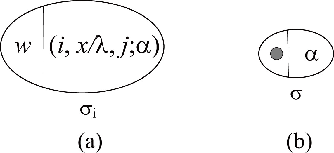
where:
In order to deal with the theoretical problems, TPS is usually described in the form of formal language framework [8, 17]. The TPS contains
where:
The FTPS consists of
As usual in TPS, the
Note that fuzzy number and fuzzy logic are integrated in FTPS. Therefore, a variety of fuzzy numbers such as fuzzy number in
Usually, an interval-valued fuzzy number
where
Linguistic values and the corresponding interval-valued fuzzy numbers
Suppose that
Then, two arithmetic operations for interval-valued fuzzy numbers can be defined as follows:
where for
In this study, FTPS is used to realize fault diagnosis of power systems, even if there are some incomplete and uncertain status information about protective devices and circuit breakers. For the FTPS-based fault diagnosis model, its initial information is from an SCADA system, which is equipped together with power systems. The SCADA system can be a centralized system or a distributed system, and it can provide the status messages of protective devices, such as normal or alarm messages. According to these messages, we can easily obtain the operational messages of protective devices as initial inputs of the FTPS-based fault diagnosis model.
The diagnosis process can be described as follows. Firstly, the operational messages of protective devices are retrieved from SCADA system; Secondly, FTPS is used to build a fault diagnosis model for each suspicious line section in outage area; Thirdly, the fault diagnosis models use the reasoning algorithm to obtain fault confidence degrees of suspicious faulty sections. Finally, faulty sections can be identified according to their fault confidence degrees.
(a) A simplified transmission network, and (b) its fault diagnosis model based on FTPS.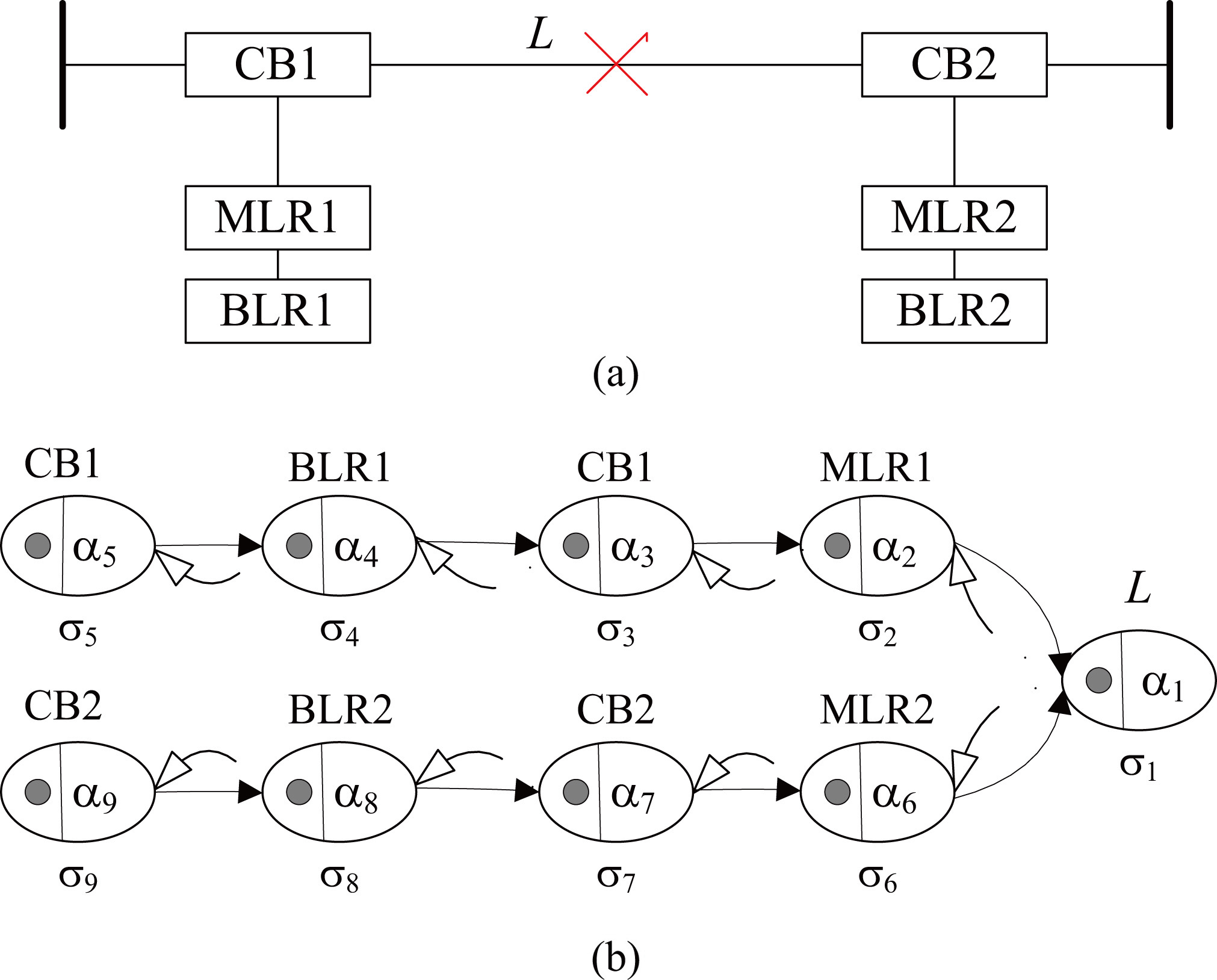
The causal relationship between a faulty section and its protective devices in power systems can be modeled by FTPS. Figure 2a shows a simplified transmission network, including a line section (L), two circuit breakers (CB1 and CB2), two main protective relays (MLR1 and MLR2) and two backup protective relays (BLR1 and BLR2). Suppose that a fault occurs at line L, which leads to the operation of main protective relays MLR1 and MLR2 and the tripping of circuit breakers CB1 and CB2. If MLR1 (MLR2) fails to trip CB1 (CB2), BLR1 (BLR2) will take over and trip CB1 (CB2). Thus, fault diagnosis model of the simplified transmission network can be built by a FTPS, shown in Fig. 2b. The FTPS consists of nine cells, which are associated with L, MLR1, MLR2, BLR1, BLR2, CB1 and CB2 respectively, where cell
Usually, the knowledge of dispatchers and experts may contain some linguistic terms, and the status of devices may have some degree of uncertainty. Table 1 gives an example, which indicates linguistic terms and the corresponding interval-valued fuzzy numbers. Usually, linguistic terms are intuitive and easy to understand for humans and have been widely used in application of fuzzy technique [4, 5]. The causal relationship between a faulty section and its protective devices can be described by a fuzzy implication rule, of the form “IF
IF a fault at line section L THEN relay MLR operates (CF IF MLR operates THEN CB tripped (CF IF MLR operates and CB fails THEN BLR operates (CF IF BLR operates THEN CB tripped (CF IF BLR operates and CB fails THEN SLR operates (CF IF SLR operates THEN CB tripped (CF IF MLR and BLR do not operate THEN CB tripped (CF
Note that “VH”, “H” and “L” are three linguistic terms that correspond to three interval-valued fuzzy numbers in Table 1. In this study, the judgment criterion is used: if the confidence degree
The causal relationship between a faulty section and its protective devices will be modeled by FTPS. Since the causal relationship between each faulty section and its protective devices corresponds to a FTPS, we can construct a FTPS for each suspicious faulty section. Thus, FPTSs of all sections form a whole fault diagnosis model. These FTPSs receive status messages from SCADA system as their inputs, and each FTPS achieves the forward computing (reasoning) by the rules in cells. As usual in TPS, cells in FTPS work in parallel. Moreover, these FTPSs are independent of each other, so they can be executed in parallel.
According to the working mechanism of FTPS, a forward reasoning algorithm is developed in this study. To illustrate the algorithm, a called connection matrix is introduced, and it is defined as follows.
where
To describe the mechanism of FTPS, an operation
where
where
The forward reasoning algorithm based on FTPS
The results computed by the reasoning algorithm for sections in case studies
From Table 2, we can see that the inputs of the reasoning algorithm are the status messages from SCADA system, which form initial vector
A 345 kV transmission system, where symbol “m” refers to the main protective relay, “b” represents the nearby backup relay, and “s” represents the remote backup relay.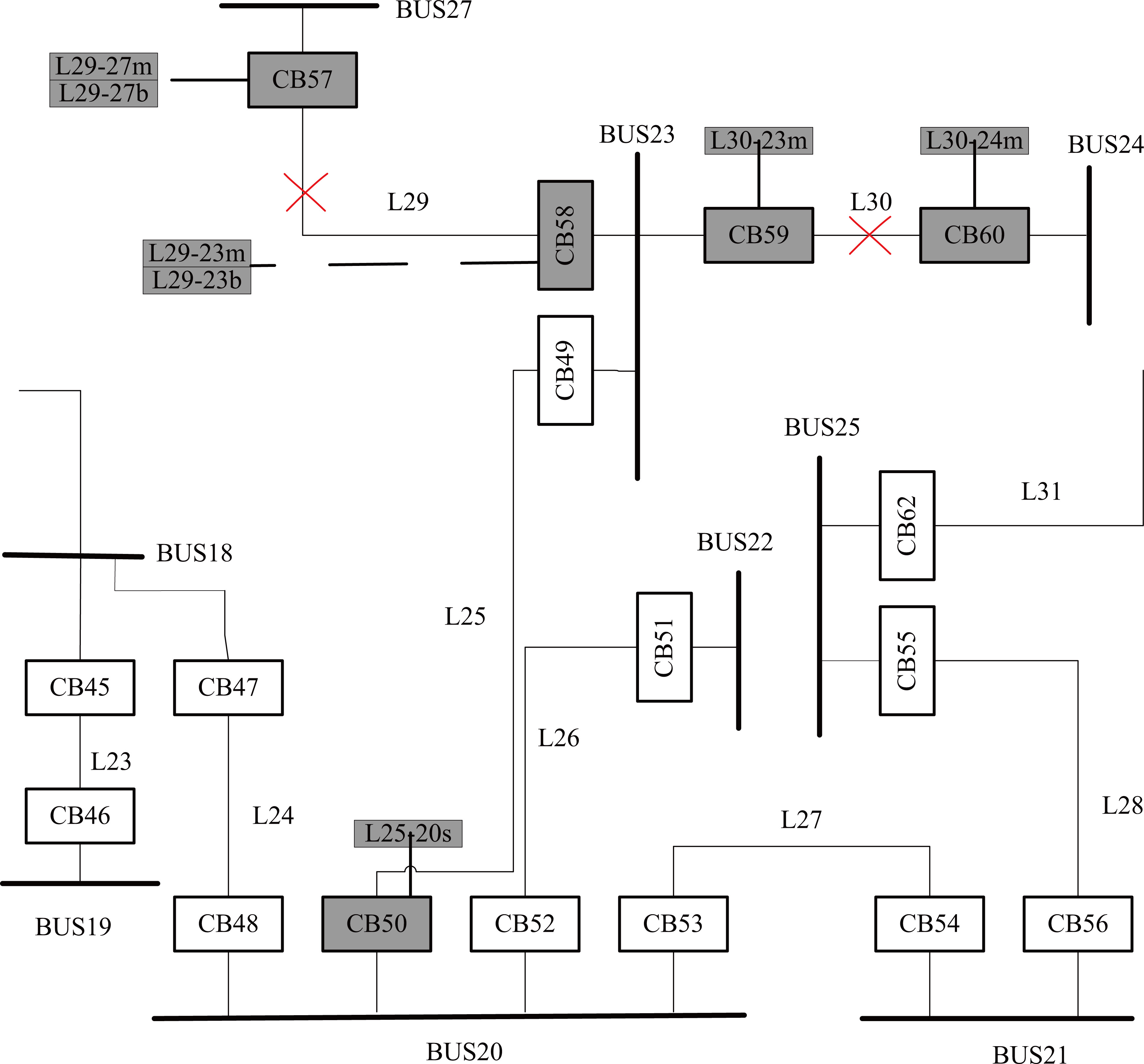
In this section, case studies of a power system are analyzed to demonstrate the effectiveness and superiority of the proposed FTPS: a 345 kV transmission system, shown in Fig. 3. The transmission system has 18 system Sections 17 circuit breakers and 60 protective relays. For the convenience of description, some notations are described as follows: a bus, line and circuit breaker are represented by BUS, L and CB, respectively.
The 18 system sections have nine buses (labeled by BUS18, BUS19, …, BUS25 and BUS27 respectively) and nine transmission lines (labeled by L23, L24, …, L31 respectively). The 17 circuit breakers (CBs) are labeled as CB45, …, CB60 and CB62. The 60 protective relays are composed of 26 main protective relays (BUS18m, …, BUS25m, BUS27m, L23-xm, …, L31-xm), 17 nearby backup relays (L23-xb, …, L31-xb) and 17 remote backup relays (L23-xs, …, L31-xs). Three case studies of the example will be discussed: single fault, complex faults and multiple faults with incomplete and uncertain status information. The results computed by the proposed reasoning algorithm for the sections in case studies are provided in Table 3.
Case 1 (Single fault without failure devices)
Suppose that a fault occurs at line L29, shown in Fig. 3. The fault leads to the operation of main protective relays L29-29m and L29-23m and the tripping of circuit breakers CB57 and CB58 without malfunction and rejection. The information from SCADA system indicates that all protective devices correctly operate: main protective devices L29-29m and L29-23m operate and circuit breakers CB57 and CB58 trip.
Fault diagnosis models based on FTPS of (a) L29 and (b) L30.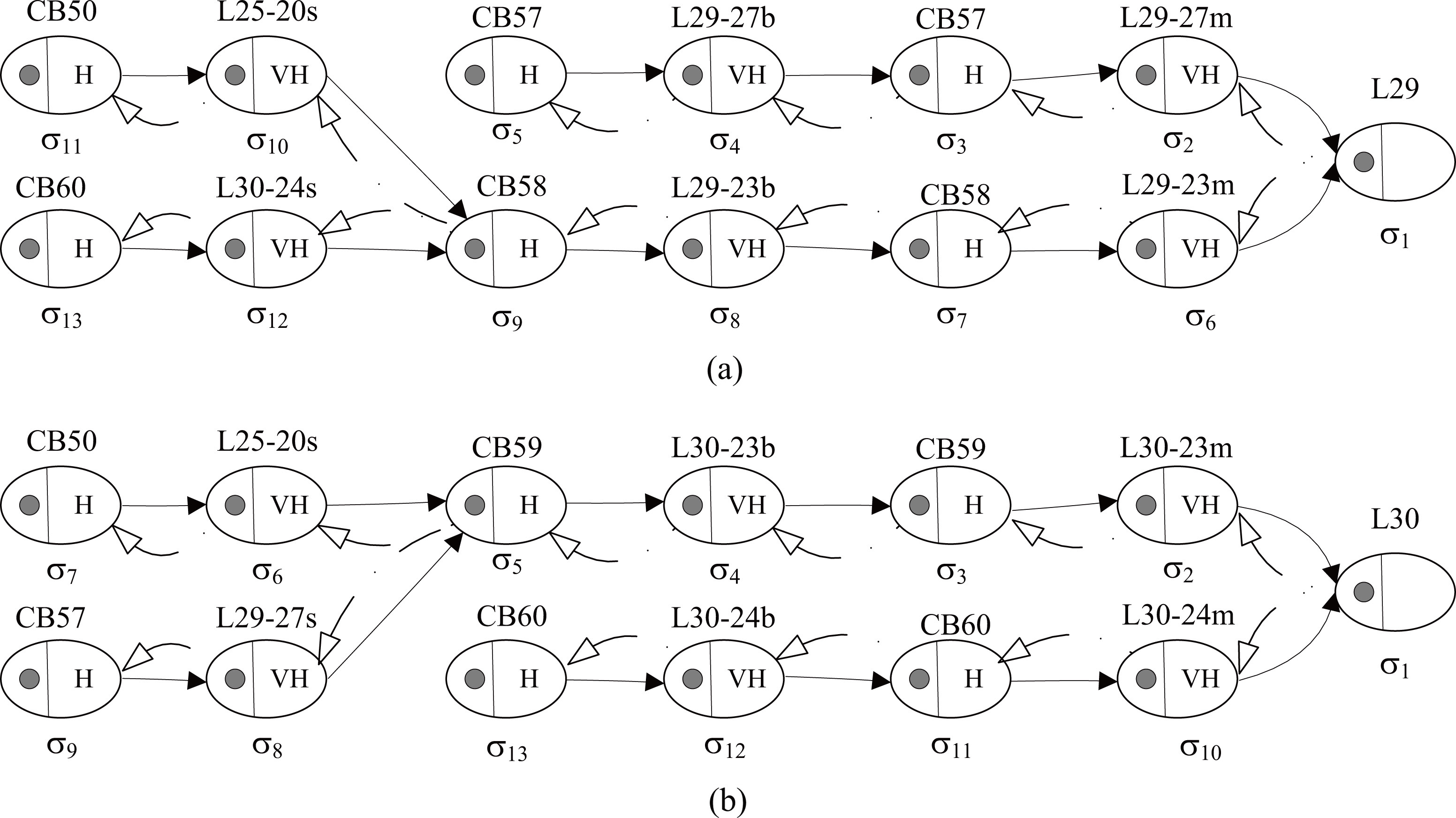
The fault diagnosis model of L29 can be constructed as Fig. 4, which consists of 13 cells (
According to status messages from SCADA system, initial configuration vector is set to be
When
Suppose that complex faults occur at lines L29 and L30, shown in Fig. 3. For line L29, main protective relays L29-27m and L29-23m operate to trip circuit breakers CB57 and CB58, but they fail. Thus, backup protective relays L29-27b and L29-23b operate to trip CB57 and CB58. Another fault at L30 causes the operation of main protective relays (L30m-23m and L30-24m) and the tripping of CB59 and CB60. There is also an obscure operation in zone 2: backup relay L25-20s causes CB50 to be tripped. Status messages retrieved from SCADA system are as follows: the operated relays are L30-23m, L30-24m, L29-27m, L29-23m, L29-27b, L29-23b and L25-20s, and the tripped CBs have CB50, CB57, CB58, CB59 and CB60.
The fault diagnosis models of lines L29 and L30 can be constructed by two FTPS, shown in Fig. 4a and b, respectively. The two FTPS contain each 13 cells, (
Case 3 (Multiple faults with uncertain information)
The status messages from the SCADA system show that the operated relays are L24-18m, L24-18s, L24-20m, L24-20b, L25-23m, L26-22s, L27-21s and B22m, and the tripped CBs have CB47, CB48, CB49, CB51 and CB54. Moreover, there are two possible information with the faults: one is that the operating of L24-20m and the rejection of CB48 result in the operating of L24-20b and the trapping of CB48 again; another is that L24-20b is an incorrect tripping signal.
Fault diagnosis models based on FTPS of (a) L24, (b) L25 and (c) B22.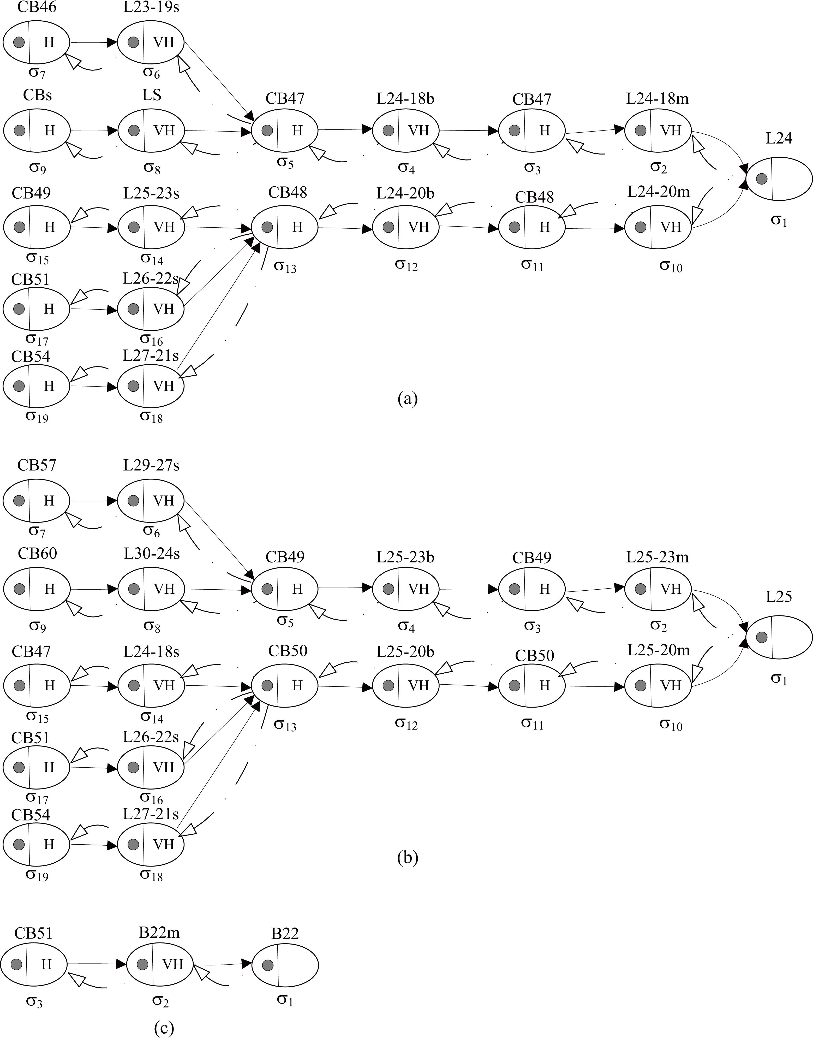
Firstly, fault diagnosis models of L24 and L25 are constructed in Fig. 5a and b, respectively. The two FTPS have each 19 cells, where
Fault diagnosis models based on FTPS of (a) L26 and (b) L27.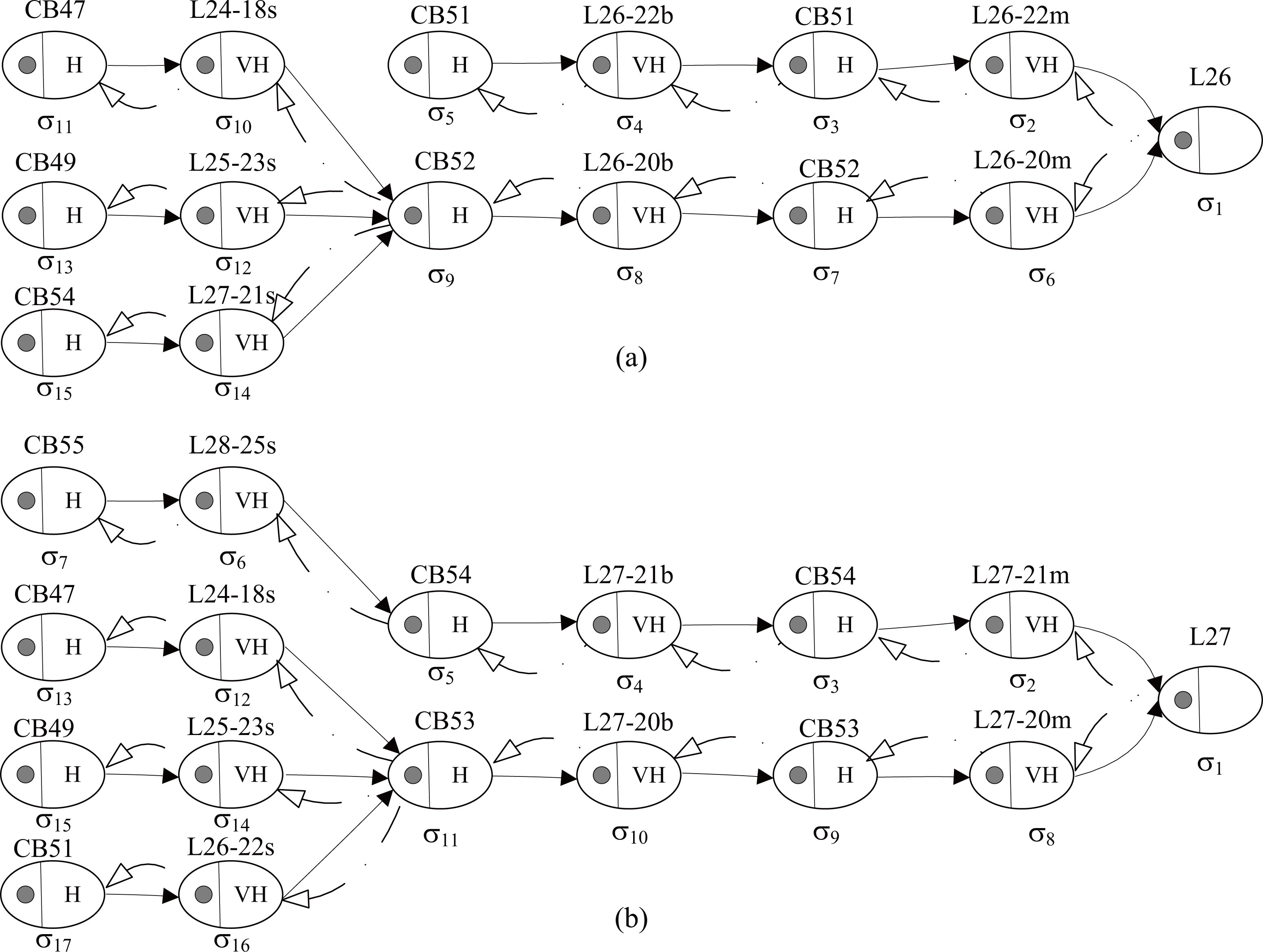
The fault diagnosis model of B22 are provided in Fig. 5c, which has three cells and
Figure 6a and b show fault diagnosis models of L26 and L27 respectively, which contain 15 cells and 17 cells respectively. Based on status messages from SCADA system, we can determine that initial configuration vectors are
The 345 kV transmission system has been discussed in a number of literatures, for example, fuzzy logic [6], fuzzy relation [7] and fuzzy digraph model (FDM) [3]. The example is used to compare the abilities of FTPS and other three diagnosis methods on diagnosing complex faults with failure devices and incorrect signals and multiple faults with uncertain information. The comparison results of the four diagnosis methods in Cases 2 and 3 are provided in Table 3.
Comparison analysis on Case 2
The diagnosis results of FTPS are the same to that of FDM [6]: L29 and L30 are recognized as the faulty sections. The results in literature [6] showed that FL method can diagnose the faulty Section 30. However, L29 is not recognized as a faulty section because an error occurs. The error is caused by some incorrect signals. In literature [7], the membership degrees of L30 and L29 obtained by FR method are 0.998 and 0.509 respectively. Therefore, L30 is distinguished as a faulty section because of its high membership degree. However, L29 is not identified as a faulty section because of its lower membership degree and an error existed in the line. The error is caused by the incorrect operation of L25-20s associated with L30.
In summary, FTPS can distinguish all faulty sections, even if there are the incorrect signals. Therefore, FTPS are suitable to deal with complex fault problems with failure devices and incorrect signals.
Comparison analysis on Case 3
In this paper, lines L24, L25 and B22 are distinguished as the faulty sections with the confidence level VH or H. But, lines L26 and L27 are identified as the non-faulty sections because of their lower confidence levels. Note that Case 3 was not considered in FDM [3].
For FL [6], B22 is distinguished as a faulty section and L26, L27 are judged as the non-faulty sections. However, FL method can not identify whether L24 and L25 are the faulty sections because an error occurs.
The membership degree of B22 obtained by FR method [7] is 0.937, so it is distinguished as a faulty section. The membership degrees of L24 and L25 are 0.673 and 0.792, respectively. Since there is the rejection device in the line and the MPRs in lines L24 and L25 do not operate, L24 and L25 are not identified as the faulty sections even if they have higher membership degrees.
The comparison demonstrates that FTPS can effectively deal with multiple fault problems with uncertain information. In addition, the fault confidence levels represented by interval-valued fuzzy numbers provide a quantitative description of the faulty components and make the diagnosis results more reliable. Owing to linguistic terms including uncertainty in certain extent are more flexible than probability values, the interval-valued fuzzy numbers corresponding to the linguistic terms provide a more intuitive way for experts and dispatchers to understand the diagnosis results.
Comparisons between FTPS and other fault diagnosis methods
Comparisons between FTPS and other fault diagnosis methods
FSNPS has two types of neurons: proposition neurons and rule neurons. Proposition neurons are used to express fuzzy propositions in fuzzy production rules, while rule neurons are used to describe the fuzzy production rules. When modeling a fault diagnosis problem of power systems, it is first expressed as a set of fuzzy production rules, and then FSNPS is used to model the fuzzy production rules. The reasoning process of fuzzy production rules is realized by the firing principle of neurons.
FTPS contains only cells of single type, which have the communication rule with weight except the objects. The basic principle of fault diagnosis is using FTPS to model the causal relationship between faulty components and their protective devices. Moreover, reasoning process of fault diagnosis is achieved by communication mechanism of objects in cells.
Note that fuzzy production rules used by FSNPS are usually retrieved by domain experts. This may be a difficult task for the different power systems. However, FTPS-based fault diagnosis model is constructed only according to the causal relationship between faulty components and their protective devices, and the causal relationship has been determined when a protective system is designed. Therefore, FTPS is simple and easy to use. In addition, FTPS uses a less number of cells and has a less amount of calculation compared with FSNPS for the same fault diagnosis problem.
Conclusions
In this paper, TPS has been extended to present a new variant, FTPS, by integrating interval-valued fuzzy numbers and introducing communication rules with weight. FTPS can well express the causal relationship between a faulty section and its protective devices in power systems and deal with incomplete and uncertain messages from SCADA system. Therefore, FTPS provides a good diagnosis solution due to its graphical modeling ability and intelligent reasoning process, and it also provides a more convenient way for readers to understand the process of fault diagnosis in power systems. Moreover, FTPS has a fast diagnosis process because of its distributed parallel computing ability. In addition, FTPS can adequately display the fault-tolerant capacity of the proposed method due to using interval-valued fuzzy numbers. The case studies on power transmission systems have demonstrated that the proposed diagnosis method can effectively and fast deal with simple fault, complex faults and multiple faults with protection devices and CBs failure, incorrect and uncertain SCADA data. This paper mainly focused on application of FTPS in fault diagnosis of power systems. However, its theoretical problem is a future work. In addition, some other application scenarios will be further discussed, for example, meshed parts of power systems and substations.
Footnotes
Acknowledgments
The authors would like to thank the anonymous reviewers for their very insightful and constructive suggestions. This work was partially supported by the National Natural Science Foundation of China (No. 61472328), Chunhui Project Foundation of the Education Department of China (Nos. Z2016143 and Z2016148), and Research Foundation of the Education Department of Sichuan province (No. 17TD0034), China.