
Abstract
For the most part, robots perform best in highly structured environments, where objects are in well-known, predictable locations. Another way to describe this is that robots are not considered agile. But, in order for them to be useful to small manufacturers and to also allow larger manufacturers to offer more automated customization of high volume parts, they need to be. In this paper, we describe various technologies that are being developed at the National Institute of Standards and Technology (NIST) in conjunction with outside organizations, such as IEEE, which can be used to enhance the agility of manufacturing robot systems. We validate these technologies using two industrially-relevant use cases. The first deals with task failure identification and recovery and the second deals with robot dynamic retasking. These use cases were successfully performed using a formal knowledge representation, a graph database, a perception system, a high-level and low-level planning system, as well as an overall architecture which brought all of the components together.
Introduction
To address the new model of high-mix and low-volume production, the paradigm of manufacturing systems has been moving from mass production and dedicated manufacturing lines toward mass customization and more flexible and agile production systems [23]. The agile manufacturing paradigm was formulated in response to the constantly changing environment and as a basis for returning to global competitiveness. Agile manufacturing can be defined as the capability of surviving and prospering in a competitive environment of continuous and unpredictable change by reacting quickly and effectively to changing markets, driven by customer-designed products and services [20]. In this paper, an agile robotic system is a system that has the ability to accomplish changeover between the manufacture of different assemblies. In this case, rapid changeover is defined as the ability to move from the assembly of one product to the assembly of a similar product with a minimum of change in tooling and program.
Today’s robots are adept at doing the same thing over and over very effectively and efficiently. But when it comes to being agile enough to respond to a consumer’s varied and unpredictable needs, robots often struggle. Getting a robot to perform even a simple task is very complex, so laborious and costly that it is worthwhile only when needing to do so very infrequently. Robots are used in manufacturing tasks only to perform processes that are repeatable with little variation. As a consequence, if a consumer wants a customized product, it is probably not going to be cost-efficient for a company to employ a robot to produce that item.
The National Institute of Standards and Technology (NIST) Agility Performance of Robotic Systems project (APRS)1 is addressing this challenge. The goal of this project is to enable agility in manufacturing robot systems and to develop the measurement science which will allow manufacturers to assess and assure the agility performance of their robot systems. Key areas of robot agility include:
The ability of a robot to be rapidly retasked without the need to shut down the robot for an extended period when a new operation needs to be performed. The ability of a robot to recover from errors, so that when a part is dropped, for example, the robot can assess the situation and determine the best way to proceed to accomplish the goal. The ability to quickly swap in and out robots from different manufacturers, so that a company is not tied to a single robot brand.
This paper focuses on the first two bullets, namely, the ability to rapidly retask robots and the ability for the robots to recover from errors.
At the lowest levels, a robot needs a way to internally represent information about itself, its capabilities, and attributes of objects in the environment. NIST has chaired an IEEE Working Group which has published the IEEE 1872 Standard (Core Ontology for Robotics and Automation) [22]. This standard provides a starting point for representing characteristics of objects in the environment and the capabilities of the robot. Also needed is a way to neutrally represent tasks and plans so that they can be easily understood and shared among different robot systems. NIST is developing the Canonical Robot Command Language (CRCL) [32] which is a low-level messaging language for sending commands to, and receiving status from, a robot. It is intended primarily to provide commands that are independent of the kinematics of the robot that executes the commands. This allows robots to be more easily swapped in and out since the robot commands are represented in a robot-agnostic format. CRCL includes control of Cartesian- and joint level motion, gripper and tooling selection and activation, and reporting of robot status such as current position and execution state. The CRCL message set is defined in Extensible Markup Language (XML) Schema, and messages are conveying using XML across network Transmission Control Protocole (TCP)/Internet Protocole (IP) sockets. A CRCL-to Robot Operating System (ROS) proxy application was written to validate that CRCL can convey information typical of industrial robot applications. The proxy behaves as a server, accepting client connections, reading XML requests for motion or other robot actions, writing XML status messages, and calls the underlying ROS motion system, MoveIt!, to carry out the tasks. The CRCL specification and program tools are included in the Robot Operating System - Industrial (ROS-I) distribution (
Using two industrially-relevant use cases, NIST validated these technologies and implemented those use cases on two robots in the Robot Agility Laboratory on the NIST campus. The goal of this paper is to show how the technologies that are being developed at NIST, described at a high level in the preceding paragraph, can be used to enhance robot agility. Although we describe an architecture that implements these technologies, this is only used as an example of how the technologies can be applied; we are not necessarily proposing that this is the only (or best) architecture to enhance robot agility. The architecture and interfaces were designed based on the knowledge of the implementer. The authors intend to investigate the C++ language and ROS in future efforts.
What is novel about this work is the ability for a robot to be dynamically retasked and to recover from errors without the need for any preprogrammed plans. The limited amount of agility that is typically built into industrial robots usually relies on a predefined set of possible errors that could be experienced and a predefined set of plans that are executed when these errors occur. The same can be said for rapid retasking, where a preprogrammed set of plans is generated that a user can quickly (or sometimes not so quickly) switch between depending on the plan they want to perform. The work described in this paper does not rely on preprogrammed tasks or plans. Instead, based upon the perceived state of the world, known robot capabilities, and desired goal, the robot generates plans on its own. This allows for a more “agile” system, being able to handle assemblies and errors that may not have been predicted.
The use cases presented in this paper deal with kitting. Kitting is the process in which several different, but related items are placed into a container and supplied together as a single unit. Kitting itself may be viewed as a specialization of the general bin-picking problem [8, 36]. In industrial assembly of manufactured products, kitting is often performed prior to final assembly. Kitting, like many other manufacturing processes, is performed manually when there is a large variation of products that needs to be assembled. Automated solutions often can not handle this variability, which is the challenge that this paper is addressing.
This paper is organized as follows. Section 2 describes related efforts focusing on robot agility and describes how they compare to the work described in this paper. Section 3 provides an overview of the use cases we are targeting, how they were determined, and the challenges that each introduces. Section 4 describes the overall agility architecture along with the integrated components and the role that each component plays. Section 5 describes how the architecture was validated through its application to two use cases. Section 6 provides some early experimental results by comparing human kitting vs. automated kitting. Section 7 provides a discussion of how the robot agility realized by the technologies described in this paper can be evaluated through a proposed set of test methods and metrics. Section 8 concludes the paper.
Software architectures for industrial robots require a significant iteration and coordination with the increasing hardware elements that make up current robotic systems. The portability, reusability, extensibility, adaptability, and interoperability of an open robotic platform would encourage other researchers to use available implementations instead of developing their own implementation for each robot. In [35], Rossano et al. describe easy robot programming concepts from an industrial perspective, examining five programming approaches (icons, data-flow diagrams, offline CAD, wizard-guided, and lead-through), and concluded that none provides the best solution for all experience levels and use cases.
Numerous middlewares such as ROS (Robot Operating System) [34], OROCOS (Open Robot Control
Robust methods for representing, generalizing, and sharing knowledge across various robotics systems are important in many domains of robotics research and application. In industrial robotics, many efforts are using the interaction between ontologies and model-driven approaches. The core ontology, ROSETTA (RObot control for Skilled ExecuTion of Tasks in natural interaction with humans; based on Autonomy, cumulative knowledge, and learning) [37], focuses on simplifying interaction between the user and an automated robotic system while ensuring human safety in the manufacturing process. Manufacturing processes are divided into tasks, each realized by some set of skills (primitive or compound). RoboEarth [40] is a project aimed at creating a global repository for all knowledge relevant to a robotic system, including information on environments, object models, action recipes, and semantic information. One of the key elements of RoboEarth is to allow developers to create general robot task instructions rather than programming individual robots on a case-by-case basis. Knowledge representation and processing are handled by the KnowRob system [39]. More recently, the standard “P1872-2015: core ontologies for robotics and automation (CORA)” [17] specifies the main, most general concepts, relations, and axioms of robotics and automation (R&A), and serves as a reference for knowledge representation and reasoning in robots as well as a formal reference vocabulary for communicating knowledge about R&A between robots and humans. The ontology discussed in this paper is consistent with CORA and is specialized to enable agility in industrial robotics. The infrastructure of our ontology was built to convert the robotics concepts into various representations that could be directly applied to the robot control system. With robots being more likely to be reconfigured multiple times to adapt to change in production, the expansion of automated robotic systems in SMEs is possible with automatic program generation and model-independent robot control. These processes will allow for easier use of robots in more complex tasks and may shorten the time required for setups and therefore speed up the manufacturing of new products. Current industry practice for robots is to rely on vendor-supplied tools for online programming where an operator uses a teach pendant to sequentially move the robot’s tool center point through the desired points [38, 11]. In industry, this type of robot programming can be justified economically only for production of large lot sizes. However, this method is very tedious and time consuming; requires a considerable amount of work-related skills, robotics knowledge, and experience; and the robot cannot be used for production during the teaching period. Moreover, there is lack of flexibility and reusability as the teaching process has to be repeated again for a workpiece with only a slight difference.
Agile tasking of robotic systems is possible using offline programming (OLP) [30] supplemented with calibration, modeling, and sensing. OLP offers many advantages over the online method including not using the actual robot, the quick incorporation of program by only substituting the necessary part of the program, and minimizing the chance of errors since the programs can be prechecked. Ozaki et al. [29] developed a technology to automatically generate robot motion programs, automatically convert them to a data format suitable for the robot to be used, and transfer the data to the robot. The authors generate the robot motion trajectory data from a simulator using a common language (SLIM) and then convert this common language to the manufacturer’s motion program via a translator.
Tasking robots the same way regardless of their manufacturers and models is also promoted by robot messaging specifications, which focus on standardizing the format and content of messages between robotic system components and applications. One example is the Joint Architecture for Unmanned Systems (JAUS) that aims at promoting interoperability between unmanned vehicles [12]. In the manufacturing domain, the Association for Manufacturing Technology sponsored an internet-based standard for communicating with manufacturing equipment called MTConnect [15]. The MTConnect standard enables manufacturing equipment to provide data in structured XML rather than proprietary formats. MTConnect-compliant agents run on the equipment and client applications to provide visualization and other useful capabilities that work with any machine. In the research described in this paper, the authors developed CRCL based on the messaging specification approach similar to JAUS and MTConnect.
APRS framework shows the organization that is repeated for both the Fanuc and Motoman robots. Sense: A vision system uses cameras to capture the poses of parts and trays in the environment. Information gathered from the vision system is used to create new elements or to update existing ones in the database using the Java Database Connectivity (JDBC). Model: An ontology is created and then converted into a graph database. Information from the vision system is used to update existing poses of objects and their relationships in the database.Act: Task-level planning is performed with the Planning Domain Definition Language (PDDL). The generated actions in the plan are converted into their Canonical Robot Command Language (CRCL) counterparts and executed by the robot(s). Poses of objects to be manipulated by the robot(s) are retrieved from the database.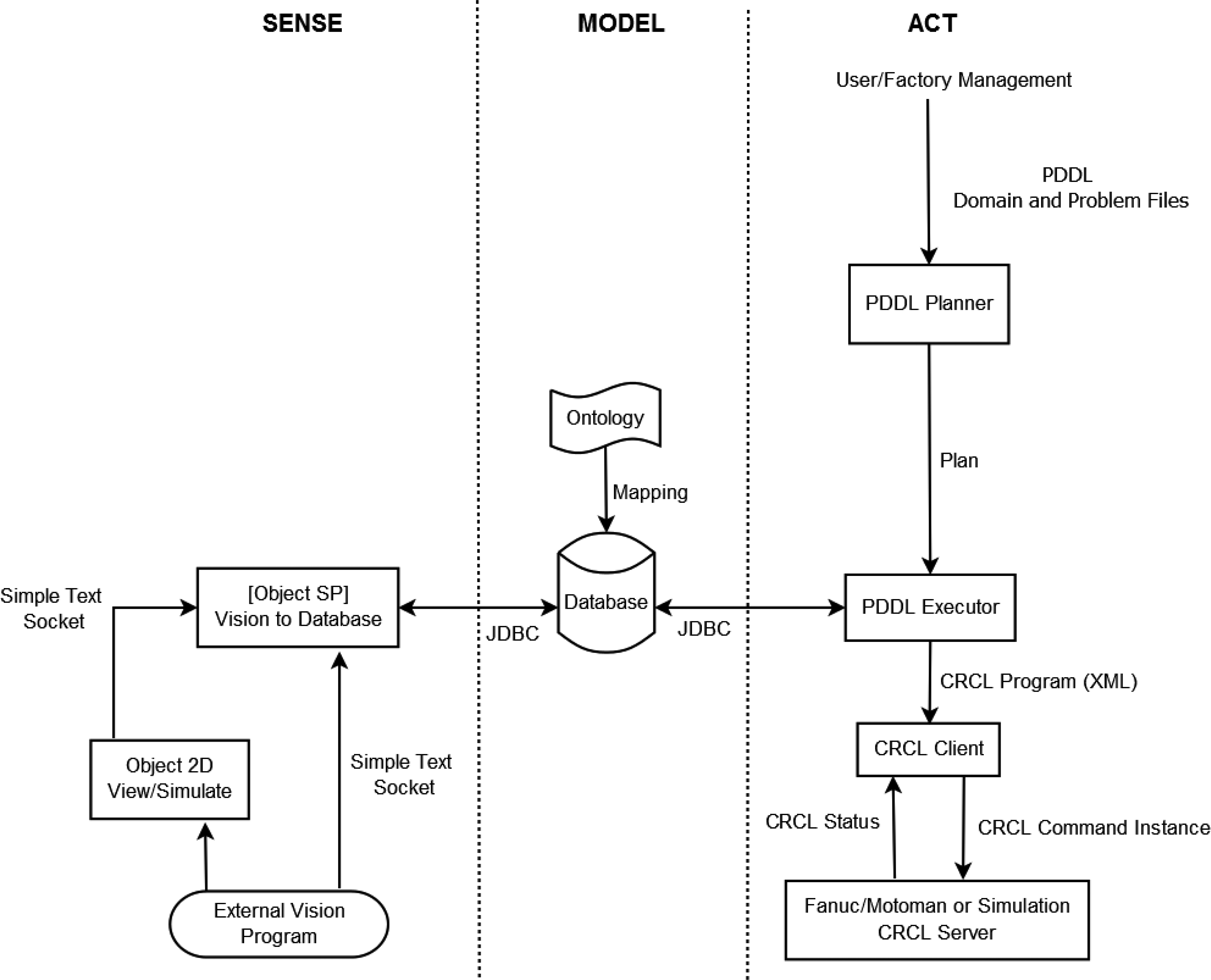
In order to determine an appropriate and relevant set of use cases to leverage some of the challenges described in the introduction, the team performed the following:
Reviewed numerous robotics roadmaps, including “A Roadmap for US Robotics: From Internet to Robotics” [1], Conducted telecons and performed site visits to over 20 industrial and academic partners, Held discussions at various standards meetings and conferences, such as the International Conference on Robotics and Automation (ICRA), the Intelligent Robots and Systems (IROS) Conference, and the International Conference on Automation Science and Engineering (CASE).
From this research and interaction, the following software-related themes relating to robot agility became evident, which are consistent with the challenges described in the previous section. While these challenges are at different levels of abstractions, all focus on the core issue of robot agility.
Many of the robots being used in industry are incapable of adapting to changing environments, which includes the location and orientation of parts in their work volume as well as variation in product specifications. This is often due to the lack of appropriate perception systems and where perception systems exist, the inability to re-plan based on this information, Once a company decides on a robot brand, they are tied to that brand because of the large infrastructural cost due to lack of interoperability, Training a robot to perform a new task (or a variation of an existing task) is very time consuming and not cost-effective unless dealing with very large lot sizes [1], Based on discussions with a number of large companies, they often have large areas of their shop floor sitting idle because the robots were trained to develop a specific product and the demand for that product is low (even though demand for other products is high).
From this information, the team developed two use cases that are meant to represent starting points to address some of these challenges. Both use cases involve kitting operations, which, as described in the introduction, involves parts that are needed for subsequent assembly operations being placed into a kit and delivered to the person or robot doing the assembly. The use cases are described below:
Use case 1: Task Failure Identification and Recovery: During a kitting operation, a robot fails to properly perform a pick and place operation. The robot detects the failure, replans to determine how to fix the error, and corrects the error without human intervention, Use case 2: Robot Dynamic Retasking: Two robots of different brands are able to be quickly programmed to perform two different kitting operations. During the operation, the robot which is performing the higher priority kitting operation fails. The second robot, from a different manufacturer, is able to be quickly re-tasked to complete the kit. No new code is written and the downtime is minimal. After the second robot completes the first robot’s task, it goes back to its original kitting operation.
A view of the agility workspace area.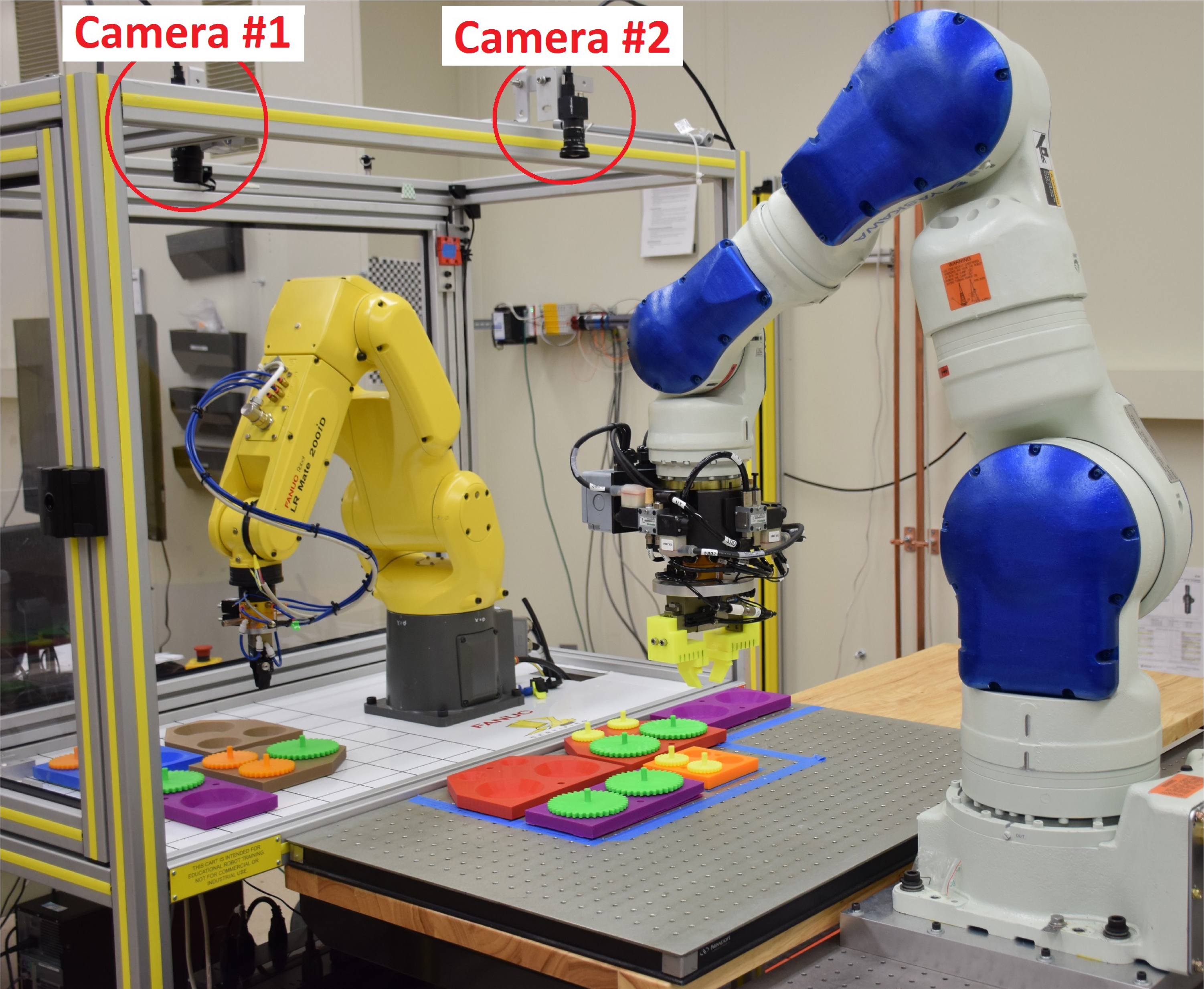
The most significant challenge in the second use case deals with the fundamentally different types of underlying representations (programming languages) that are used by the different robots. The NIST testbed contains commercial robots from both Fanuc and Motoman. The Fanuc robot uses the Karel programming language and the Motoman robot uses the Inform programming language. Examples of code written in each language are shown in Listings 1 and 2.
Listing 1: Sample Karel Code Used by Fanuc
PR[42] = PR[30]
PR[42,3] = (-80)
PR[32] = PR[31]
PR[32,3] = (-80)
PR[42] 200mm/sec FINE
PR[30] 200 mm/sec FINE
WAIT 0.10 (sec)
CALL CLOSE_GRIPPER
WAIT 0.10 (sec)
PR[42] 200 mm/sec FINE
PR[32] 200 mm/sec FINE
PR[31] 200 mm/sec FINE
WAIT 0.10 (sec)
CALL OPEN_GRIPPER
WAIT 0.10 (sec)
PR[32] 200 mm/sec FINE
EN
Listing 2: Sample Inform Code Used by Motoman
CALL JOB:HOME
CALL JOB:GRIPPEROPEN
SET ABOVEPART ZPLUS30
ADD ABOVEPART LGEAR1
MOVJ ABOVEPART VJ=50.00
MOVL LGEAR1 V=138
CALL JOB:GRIPCLOSE
MOVL ABOVEPART V=138
MOVJ HOMEPOS VJ=50.00
SET ABOVEPART ZPLUS30
ADD ABOVEPART SLOT1
MOVJ ABOVEPART VJ=50.00
MOVL SLOT1 V=138
CALL JOB:GRIPPEROPEN
MOVL ABOVEPART V=138
CALL JOB:HOME
END
The design methodology depicted in Fig. 1 shows the organization of the agility architecture. The architecture is a hierarchical architecture in which each echelon or level follows a sense-model-act paradigm. This architecture is not intended to replace sound engineering of an intelligent system, but rather as an additional step that may be applied in order to provide the system with more agility, flexibility, and the ability to be rapidly retasked. This architecture was first discussed in our previous work [5]. However, important modifications were made to make the framework more robust (e.g., user interface, database, and failure detection).
Camera #1’s view from inside the Fanuc cart.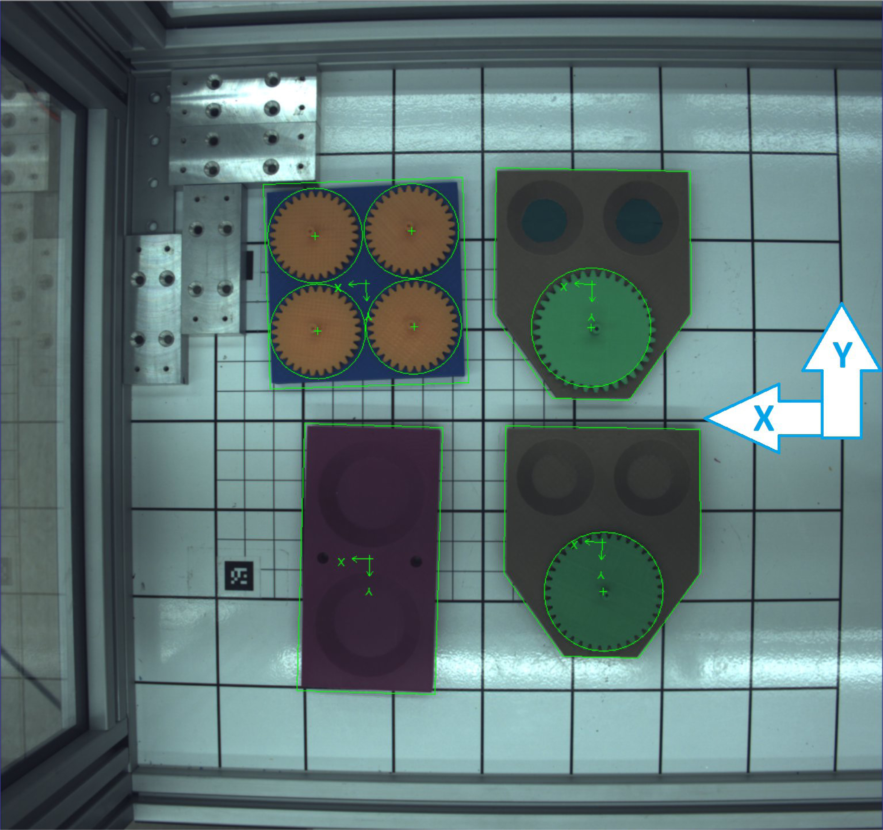
A perception system was needed in order to know which objects are available to the robots and where those objects are located in relation to the robots.
Our perception system consisted of two vision cameras mounted to the Fanuc cart workcell. The first camera, camera #1, was a 2048
Example output data from the vision system
Example output data from the vision system
A checkerboard calibration chart was used to calculate the camera’s intrinsic and extrinsic calibration parameters [49] and vision software was trained to recognize the items by first segmenting specific colors, then by analyzing and comparing the segmented color shapes to the known parts. For example, the “large gear” part was green in color, contained a jagged edge, and had a circular diameter of 10 cm.
The information about which parts have been recognized by the vision system and their position locations are stored and updated in the database. This information includes: part name,
The
The object positions reported by the vision system are then used by the system architecture to populate the database as shown by the “Object Sensory Processing (SP) Vision To Database” module depicted in Fig. 1. Currently, the positions from both the database and the vision system are expected to be in the robot’s coordinate system except that the vision system is not providing a
Information model for kitting.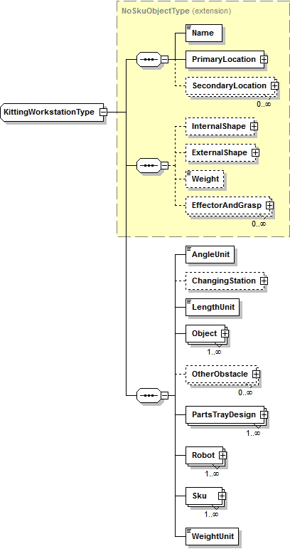
The APRS project uses a kitting workstation ontology to model both classes and instances of information in the robotic kitting domain. A class model describes relationships and data types (e.g., the class model of a person might capture a person’s name of type text and their age of type integer). An instance of a given class provides values for the data member (e.g., a person’s name is Jack and his age is 43). The class knowledge in APRS is represented in as compact a form as possible by having child classes inherit common attributes from parent classes (e.g., person class and cat class might both inherit from animal class). The Web Ontology Language (OWL) kitting workstation class files are then used as input to a tool that generates a database schema automatically.
Ontology
The APRS kitting workstation ontology is represented in files using both XML technology and OWL technology. On the XML side, the kitting workstation ontology is a “schema” written in XML Schema Definition Language (XSDL) [44, 45, 46] and the instance files are XML files that conform to the schema [43]. On the OWL side, both the model files and the instance files are written in OWL [48, 47]. The class model and instance files are initially written manually using XML technology and then translated automatically into OWL [26].
The decision of using XSDL models and XML instance files to generate OWL files emerged from lessons learned with the use of Protégé [21], a tool available for building OWL ontologies. For example, OWL’s open world assumption allows that anything might be true that is not explicitly ruled out (1) by OWL statements directly, or (2) by reasoning from statements that have been made. The open world assumption is appropriate in some contexts, however the kitting domain may be readily handled under a closed world assumption. The reader may find more information of the choice of generating OWL files from XSDL and XML formats in [25, Section III-A].
An example kitting workstation class is shown in the diagrams presented in Fig. 4, which was generated from the XSDL kitting workstation class model. In the diagrams, a dotted line around a box means the attribute is optional (may occur zero times), while a
The class shown in the figures has both a PrimaryLocation for an object and a set of SecondaryLocations. The PrimaryLocation might, for example, be the location of a part with respect to a parts tray (useful for keeping track of the completeness of the tray), while the secondary location might be the location of the part with respect to the kitting workstation (useful for graphics showing the workstation). The secondary locations are provided for the convenience of programs that manipulate workstation information. More information on this model can be found in [4, 3].
Database
To deal with dynamic information in the kitting implementation, the OWL kitting workstation class files were used as input to a tool that generates a database schema automatically. At the start of the implementation, an OWL instance file, given an initial workstation description, is read into a computer accessible database. Both static and dynamic information is represented in the database and may be accessed while the workstation is running.
The decision to map the ontology to a database was made for multiple reasons. An efficient approach was needed to store the ontology document for the ease of querying while at the same time having crucial information available for multiple robots performing kitting. During kitting, the framework (refer to Fig. 1) reads sensor information at a frequency of 1 Hz. This information is then used to create dynamic data that may be modified and made available to other modules of the framework.
To access OWL data, the authors investigated the query language SPARQL (SPARQL Protocol and RDF Query Language) [33] which is widely available. While SPARQL certainly has its strong points, the authors also identified weaknesses that directly affect the APRS project. For instance, triple stores, which are the starting point for most SPARQL applications, consume a significant amount of disk space and are slow for very large datasets compared to relational and graph databases. Moreover, RDF (Resource Description Framework) serialization of OWL can be very complex and many SPARQL engines have no or only partial understanding of the underlying OWL semantics. Due to the aforementioned reasons along with the high read/write frequency required by the framework, the use of a database was preferred to the access to the OWL file.
The authors judged that a graph database would be more appropriate than a relational database considering that a graph representation conveys the properties of an ontology in a simple, clear, and structured model [28]. The mapping between OWL components and a labeled graph can be described as follows using Fig. 5. An ontology has a top node and classes extending it, which are depicted by a “isA” relationship. Individuals that belong to a class are represented by graph nodes and “isA” relationships (e.g., part_gripper belongs to the class GripperTwoJaws). Note that a “isA” relationship is a subsumption relationship between abstractions (e.g., types or classes), wherein one class A is a subclass of another class B. Object properties are represented in the graph by labeled relationships (e.g., “hasRobot_EndEffector”). Individuals can have data properties and annotations that can be represented as node properties and relationship properties in the graph.
Graph representation of a section of the kitting workstation model.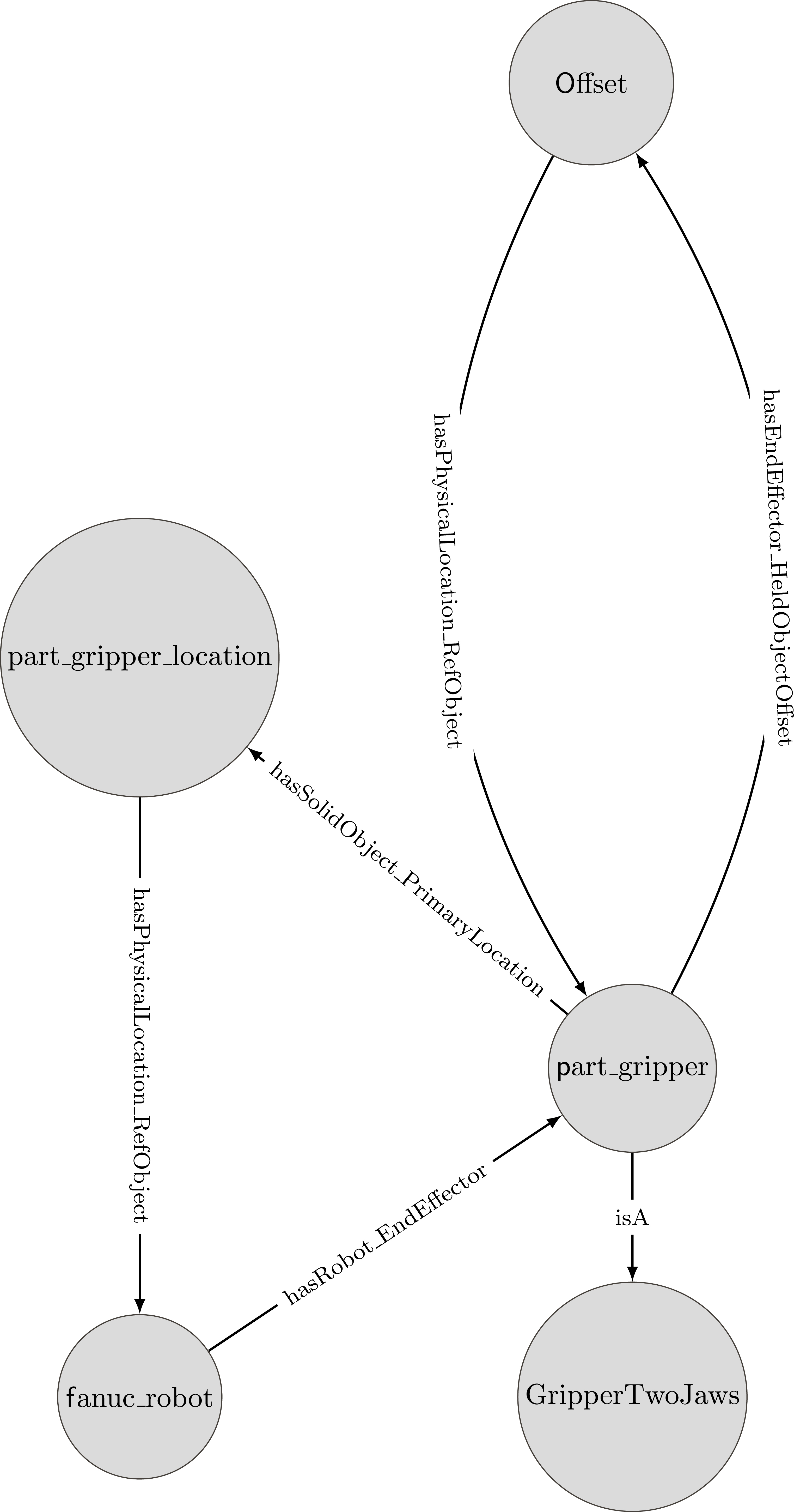
Task-level robot actions are described with the Planning Domain Definition Language (PDDL). PDDL is a domain definition language which is supported by most planners. The version of PDDL used within the project is 2.1 [18]. The feasibility of PDDL-based tools in real-world situations has been described in the literature and includes efforts such as space flight control [27] or solving vehicle routing problems [9]. In industry, efforts have been reported to use PDDL for assembly and disassembly robot systems [19] and for extending the capabilities and flexibility of robotic systems [41].
In order to operate, the PDDL planners require a PDDL file set that consists of two files that specify the domain and the problem (see [5] for a set of PDDL files). In Fig. 1, the “PDDL Planner” module copies these two files to a remote host and executes a forward-chaining partial-order planner [13] on these two files. The reader may note that the remote host is a Linux operating system since the selected planner runs only on Linux while the framework runs on a Microsoft Windows operating system. The planner then creates an additional static plan file, which contains a sequence of actions that will transition the system from the initial state to the goal state. In order to maintain flexibility, it is desired that detailed information that is subject to change should be “late-bound” to the plan. In other words, specific information is acquired directly before that information needs to be used by the system. This allows for last minute changes in this information. For example, the location of a kit tray on a work table may be different from run to run. However, one would like to be able to use the same planning sequence for constructing the kit independent of the tray’s exact position. To compensate for this lack of exact knowledge, the plans that are generated by the PDDL planning system contain only high-level actions.
Act
Low-level planning transforms the sequence of actions from a PDDL plan into a series of specific robot moves and tool actuations that are executed by the underlying robot controllers. These actions are represented in CRCL [32]. CRCL provides generic command and status definitions that implement the functionality of typical industrial robots without being specific either to the language of a plan that is being executed or to the language used by a robot controller that executes CRCL commands. Command messages include:
Cartesian motions, Joint-level motions, Actuating grippers and other tooling, Setting units, speeds, accelerations, and tolerances, Configuring status reports, Displaying messages.
The “PDDL Executor” module receives a PDDL solution file and generates a set of CRCL commands for subsets of the list of actions. This module then waits for a command set to be completed before generating CRCL commands for the next set of actions. Some commands are generated based on both the action and data in the database. Some PDDL actions will result in multiple CRCL commands, while others will not be directly linked to any CRCL command but rather change the executor’s state indirectly affecting future actions. When possible, the CRCL commands from multiple PDDL actions are combined into a single CRCL command set. The information stored in the PDDL action is typically not enough to generate the CRCL commands. For example, the PDDL action take-part includes the name of the part to take but not its current position. In order to generate the CRCL MoveTo command to move the robot to a position where the part can be grabbed, the executor consults the database to obtain a position associated with that part. A continue index marks the PDDL action where CRCL generation will continue after the robot has successfully executed the most recently generated CRCL command set. Some options can be set from within the executor to control how subsequent CRCL commands are generated. For example, when the robot needs to look for a part, the arm needs to be moved to a position where it will not occlude the vision system.
Once CRCL commands are generated, the “CRCL Client” module receives the CRCL command set and sends the commands from the command set one at a time to a CRCL server and monitors each command’s status. The module “Fanuc/Motoman or Simulation CRCL Server” reads CRCL commands and provide CRCL status updates by forwarding information to/from the Fanuc or Motoman or simulation. CRCL commands and status take place within a session with a connection to a robot. Messages are sent using a simple protocol using serial numbers to associate commands with a stream of status information. This information contains the status of active commands, any errors that may have occurred, and the state of the robot.
CRCL can be used with offline planners that create output to be stored in CRCL files, or online where CRCL is communicated in both directions via the Transmission Control Protocol (TCP). It is defined by a set of XML schema files. CRCL commands and status could also be exchanged over TCP between an operator interface and a robot controller or proxy for a robot controller. A set of related utilities have been implemented in Java and examples for sending and receiving CRCL written in Java, Matlab, C#, C++, Python, and Javascript were tested in both Windows and Linux.
This section discusses how the components and architecture described in the previous section were used to realize the two use cases detailed earlier. The implementation aspects that are common to both use cases are first described, followed by the use case-specific aspects.
Overall use case implementation details
The software that is used to implement the two use cases is written in Java and is divided such that each functional module also corresponds to a graphical user interface (GUI). The GUI allows the state, inputs, and outputs of the module to be observed and/or modified at run-time. The GUI also allows for faster debugging. In addition, all configuration parameters that were required during setup are set through these interfaces. The implementation uses two instances of the main APRS frame class, each corresponding to a separate GUI window: one for the Motoman robot and one for the Fanuc robot in the use cases described later in the paper. The two frames are controlled by a third supervisor window that can start or stop both simultaneously and initiates the transfer of control from one robot to another (Fig. 6). The supervisor shows the lists of tasks with their priorities, associated robots, and details.
Supervisor controlling two robots.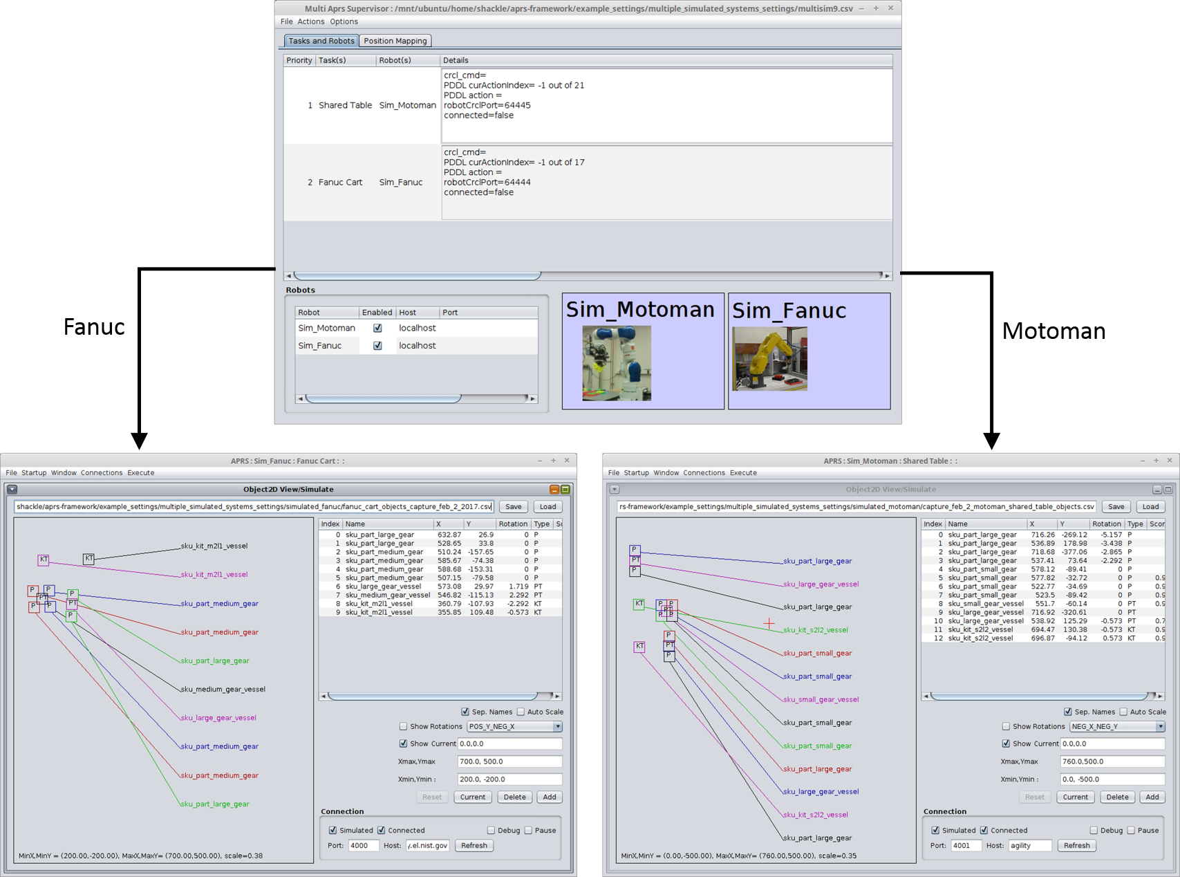
The Motoman and Fanuc GUIs maintain reference instances of all of the submodules. This is used indirectly to facilitate communication between the modules. For example, when the PDDL executor wishes for the CRCL client to begin running a CRCL program, it calls the startCRCLProgram method from its references to the instance of the common object which then calls the appropriate methods of the CRCL client. The Motoman and the Fanuc talk to the CRCL client in different ways to ensure that the correct method is being used. Many of the modules internally use multiple threads.
There are three versions of the CRCL server that use the same common base and utilities libraries: One that connects to the Fanuc robot, one that connects to the Motoman robot, and one that connects to a simple simulation. The base library contains only the code that is automatically generated from the CRCL XML schema files. The utility library provides a specialized socket class that can send and receive objects from the generated classes by converting them to/from the XML representation sent over a socket. Each of the robot specific servers therefore only has to deal with receiving objects of one of the classes derived from the CRCLCommandType type class. Moreover, each robot has to use the appropriate robot specific interfaces to accomplish the command and has to provide an instance of the CRCLStatusType class updated with data from the robot to be sent back to clients on request.
The CRCL server written in Java running on a separate computer receives CRCL commands and then sends the Motoman specific messages to the custom server running on the robot. It is important to keep state and as much code as possible on the Java/PC side where debugging and updating are much easier rather than complicating the C code where small mistakes could make the robot require rebooting and any updates require putting the robot in maintenance mode.
For both robots, since one could take advantage of the robots’ built-in Cartesian moves, there was no need to develop model specific kinematics functions, so the same server should work with other models with different kinematics from the same vendor. Since most of the work of parsing CRCL is done by existing libraries with auto-generated classes, it should be relatively easy to develop CRCL servers for other vendors.
This section describes a methodology that is capable of identifying failures and recovering from these failures during kitting operations. A failure in this context consists of incomplete kits, i.e., a finished kit that is missing one or more parts. In the first phase of the methodology, information from the vision system and the database is used to deduce the completeness or incompleteness of finished kits. In the case of kits’ incompleteness, the second phase of the methodology performs high-level replanning and generates robot actions to bring the kits to a state of completion.
Listing 3: An example of a PDDL kitting plan file
1 (look-for-parts)
2 (take-part part_medium_gear_in_pt_1)
3 (place-part slot_med_gear_kit_m2l1_1)
4 (fake-take-part part_medium_gear_in_pt_2)
5 (place-part slot_med_gear_kit_m2l1_2)
6 (fake-take-part part_large_gear_in_pt_1)
7 (place-part slot_lar_gear_kit_m2l1_1)
8 (look-for-parts)
9 (inspect-kit sku_kit_m2l1_vessel)
10 (look-for-parts)
11 (inspect-kit sku_kit_m2l1_vessel)
12 (look-for-parts)
13 (fake-take-part part_medium_gear_in_pt_1)
14 (place-part slot_med_gear_kit_m2l1_1)
15 (take-part part_medium_gear_in_pt_2)
16 (place-part slot_med_gear_kit_m2l1_2)
17 (take-part part_large_gear_in_pt_1)
18 (place-part slot_lar_gear_kit_m2l1_1)
19 (look-for-parts)
20 (inspect-kit sku_kit_m2l1_vessel)
21 (look-for-parts)
22 (inspect-kit sku_kit_m2l1_vessel)
23 (look-for-parts)
To discuss the methodology, the reader is referred to the PDDL plan described in Listing 3. This plan contains high-level actions that a robot needs to perform in order to build two kits, each containing two medium gears and one large gear (see Fig. 7).
Incomplete kit identification is performed when the action inspect-kit is encountered in the PDDL plan file (lines 9 and 11 in Listing 3). For testing purpose, fake-take-part actions were introduced in the plan file, as depicted at lines 4, 6, and 13 in Listing 3. During the execution of fake-take-part actions, the robot does not close the gripper when it goes to pick up a part, resulting in the part not being grabbed by the robot. Therefore, place-part actions that directly follow fake-take-part actions (lines 5, 7, and 14 in Listing 3) result in no part being placed in the kit tray. For safety reasons, the authors decided to apply the fault injection technique instead of using a human operator who could have manually created these failures by moving parts from the kit tray to their original parts trays.
An example of a kit that contains two medium gears and one large gear.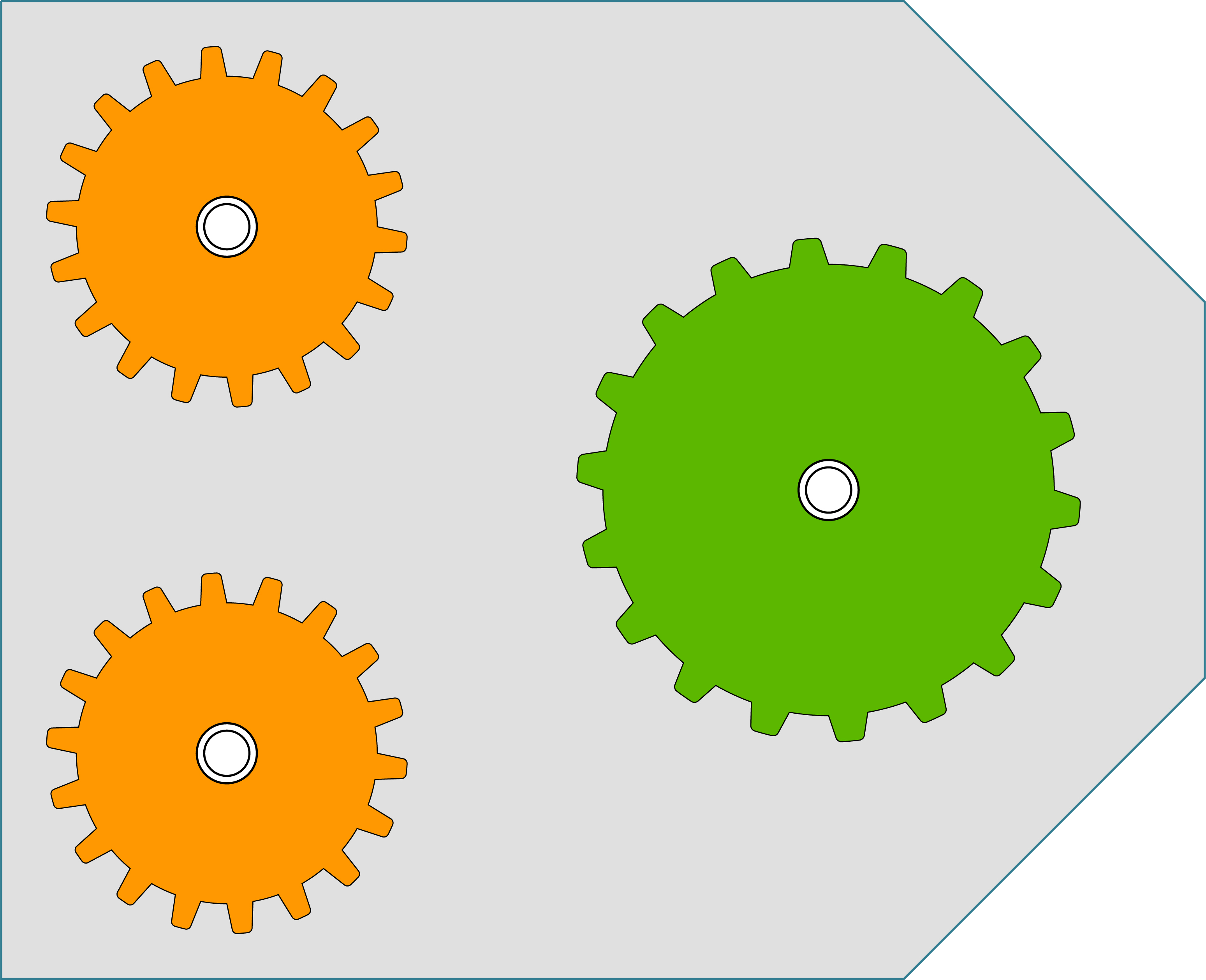
SysML activity diagram to inspect a kit after it is completed.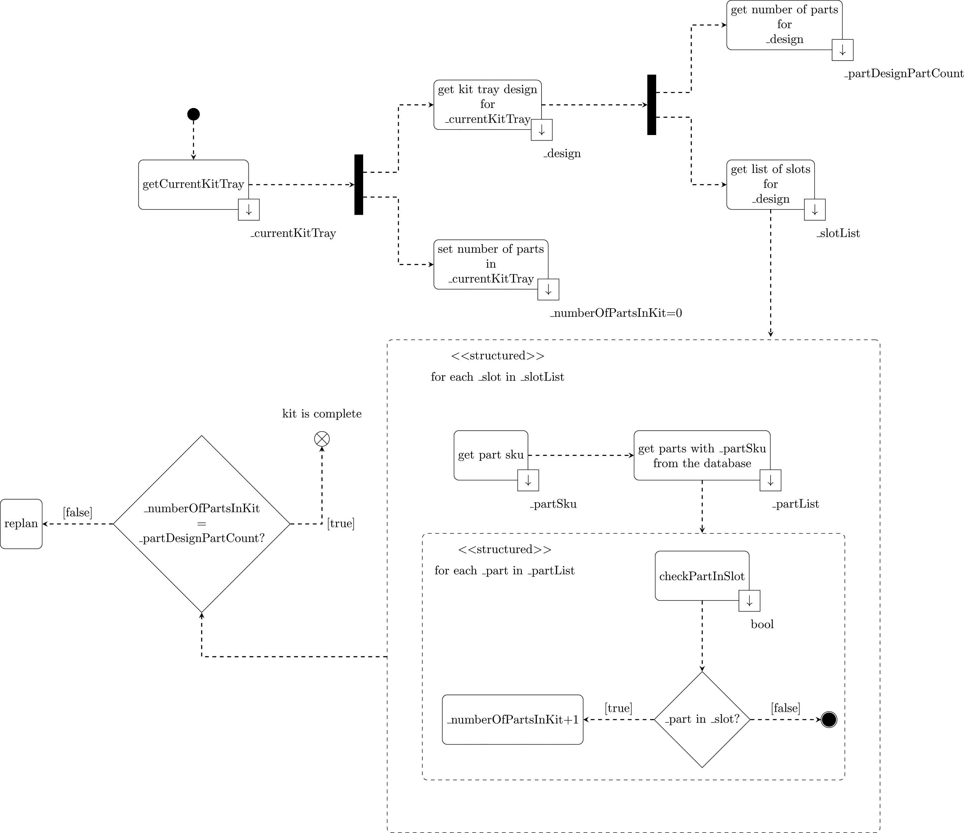
To identify finished kits that are incomplete, the authors developed the methodology that is illustrated in Fig. 8. As shown in Listing 3, a PDDL plan file may contain actions to build multiple kits. Since the action inspect-kit has the type of kit to inspect as its parameter and not the actual instance of the kit tray, it is necessary to first identify which kit tray was used to build the kit prior to inspect-kit. Identifying the current kit tray is performed by comparing the pose of each part placed by the PDDL place-part action with the current location of each kit tray. The pose for each placed part and for each kit tray in the environment is retrieved from the database, which contains the most recent data from the vision system.
Once the current kit tray is identified, the number of total parts inside this kit tray is initialized to 0. The design for the current kit tray is also retrieved from the database. A kit tray design provides information on the relative locations of the slots within the kit tray and the number of parts inside the kit tray. For each slot within the current kit tray, the type of part for this slot, using the stock keeping unit (or sku), is retrieved from the database. Examples of part sku for the kits built in Listing 3 include sku_part_medium_gear and sku_part_large_gear. A list of parts that have the corresponding sku is then retrieved from the database. From this list, the location of each part is then compared with the location of the current slot. If a part is found inside a slot, the total number of parts for the whole kit tray is incremented, otherwise, the slot is considered to be empty and is added to a list of empty slots.
After iterating through the list of slots for the current kit tray, the algorithm checks that the number of parts found inside the kit tray is the same as the number of parts found in the design. In the case both numbers match, the kit is complete, otherwise, a recovery procedure takes place.
Recovering from failures
Recovering from failures is performed when inspect-kit reports that a kit is incomplete. The recovery procedure in this case consists of dynamically generating a set of PDDL take-part and place-part actions that will replace the missing parts identified in the first phase of the methodology. The methodology keeps track of slots that are empty. For each empty slot, the part sku is then retrieved from the database. A list of available parts that have the same sku is built by querying the database. Once available parts are found, a take-part action followed by a place-part action are generated.
CRCL commands are generated from their PDDL counterparts, which are then sent to the robots. After these new actions are carried out, the kit is inspected one more time to make sure that it is complete (see lines 11 and 22 in Listing 3).
The reader may note that replanning in this case consists of a set of actions (take-part and place-part) that are called after a failure has been identified. These actions were previously stored in memory and are put on “standby” in the case a failure occurs. In the future, the authors plan to increase the complexity of the scenarios by making the robots drop parts during kitting. This type of failure will incorporate advanced replanning and the regeneration of PDDL problem files based on the current state of the world.
Use case 2: Robot dynamic retasking
Dynamic retasking is implemented in the supervisor that maintains a list of tasks and the associated robots assigned to complete them. The user can indicate at any time that a robot should be taken out of service. The list of tasks is searched to see if any task currently being executed is using that robot. If there is such a task, a search is done for a robot assigned to a lower priority task that could be reassigned to the higher priority task. When a robot needs to be reassigned, the supervisor calls methods to safely abort both tasks, transfers the robot performing the lower priority task to control by the system performing the higher priority task, and finally when the higher priority task is completed transfers that robot back to resume the lower priority task.
Safely aborting a task ensures that three things are true: 1) the robot has dropped off any parts that it might have been holding in its gripper, 2) the robot is out of the way so as not to interfere with the other robot completing the task, 3) the robot is also out of the way so as not to obstruct the vision system’s view of the parts or trays.
The supervisor calls the startSafeAbort method to complete a safe abort. startSafeAbort returns immediately rather than waiting for abort to be completed, thus allowing the supervisor to call startSafeAbort for both robots at essentially the same time and the robots can perform their actions in parallel. To complete a safe abort, the following steps are taken by each of the PDDL Executor modules when the supervisor calls startSafeAbort:
Create an XFuture instance and return it to the supervisor. A Java Future represents the result of an asynchronous computation and XFuture is a class that extends the CompletableFuture class added in Java 8. If the robot is holding a part, the current program is allowed to continue until the part is placed in the proper location. The gripper is moved to a location that will not obstruct the vision systems view or the other robot from reaching the parts or trays. Call the complete method on the created XFuture instance that will trigger any additional actions set by the supervisor.
The supervisor extends the actions taken after the startSafeAbort for the robot being disabled using the thenCompose method of the XFuture object obtained. The thenCompose method takes a method which produces another XFuture. This is obtained from the screen display system to display a message showing the user that the robot is disabled. When the display message has been shown, the XFuture is completed. This can also happen in parallel with the other robot completing the abort actions. The two futures from the two systems both being safely aborted in parallel are combined using the allOf method for a future that will only be completed when both are completed regardless of which completes first. This is then extended with additional thenCompose calls for following additional sequential operations:
Display a message indicating the robot control will be transferred. Connect the system with the higher priority task to the new robot. Set the position mapping and executor options for the new robot. Complete the high priority task. Reconnect the system with the low priority task back to the robot. Reset the position mapping and executor options. Complete the low priority task.
The supervisor also provides a tool for recording and maintaining sets of corresponding points between the two robots. With this tool, the user manually drives to any position such as the position needed to pick a part and clicks a button to record the point, moves the first robot out of the way and moves the second robot to the position to pick up the same part. Three corresponding points are sufficient but four points are preferred. It is preferable if the points cover the shared space between the robots. Covering the shared space ensures that the points are as far apart as possible. Small errors in two points close together will cause large errors in the orientation while small errors in points far apart will only result in a small errors in orientation. In addition, if the points do not cover the space the mapping is likely to be good near where the points were measured and worse as one gets farther away as the non-linear errors in either robots’ kinematics are well compensated for in that area but not in other areas.
To begin to characterize the benefit of implementing the technologies described in this paper, a small experiment was performed. The work was done in collaboration with Dr. Balakirsky’s laboratory at Georgia Tech Research Institute (GTRI), which implemented the technologies described in this paper, including CRCL and the kittingWorkstation ontology [2]. They implemented an architecture similar to the one described in this paper, with the exception of using the ROS as the underlying infrastructure. They also used a robot which was very similar to the one described in this paper. As the focus of this paper is on the technologies and not the architecture, this provides an excellent example of how the technologies can be implemented using different architectures and the benefits derived from our approach.
In both of the scenarios described in this paper (task failure recovery and robot dynamic retasking), the core goal is the same; namely, the ability for the robot to be reprogrammed in a dynamic fashion to address a change in either the task or the environment. As such, the experiments performed at GTRI focused on the amount of time it took to reprogram the robot by a person vs. by the technologies proposed in this paper. In this section, the authors focus on retasking a robot to perform a different kit, although a brief discussion is provided on task failure recovery.
Teaching pendant approach
A kitting operation at GTRI was performed which was extremely similar to the one described in this paper. In this process, a student at the university was asked to program the robot using a teach pendant to perform the kitting operation. The student was very familiar with the robot and had developed teach programs for this robot a number of times before. The student used the teach pendant that was provided with the robot and performed the programming in line with the procedures dictated in the user’s manual. To program the robot to perform the kitting operation related to the dynamic retasking, it took the student 16 min 20 s.
Development time for the APRS framework
Development time for the APRS framework
Time for retasking using a teach pendant vs. time for performing automated retasking
Automated retasking refers to the use of the framework and the technologies described in this paper to perform retasking with one of the two robots. When it comes to measuring the time taken by the robotic system to perform kitting, the time for software development and hardware configuration need to be considered. The time taken to develop the whole framework is presented in Table 2. The hardware setup consists of securely mounting the cameras with good viewpoints and setting up their cables. Software development consists of three conversion tools, the “Java GUI”, the “PDDL domain file”, the “CRCL language”, “Object recognition”, and a set of “XML instance files”. The field “Object recognition” refers to the use of a vision system by an expert to recognize all the relevant objects in the environment. The value shown in the table (960 min) accounts for eight different object types needed for the scenarios, with each object taking 2 h (120 min) to be recognized by the software. An “XML instance file” needs to be manually created for each workspace, one for the Fanuc workspace and one for the shared workspace. Each instance file can be created within 30 min. It took the team around 398 days to develop, set up, and configure the components presented in Table 2. Once these components are in place, they do not require any adjustments when new kits are introduced in the workspace, as long as these kits use a combination of the existing parts.
Table 3 shows a comparison between the time it took the student to retask a robot using a teach pendant and the time taken by the automated approach to perform retasking. As mentioned earlier, the teaching pendant approach took 16 min 20 s and this is reported in the column titled “Teach pendant”. The column labeled “Automated retasking” describes the components of the framework that need to be modified when retasking a robot. The values displayed in this column are for one single kit. In this section, retasking refers to the ability of a robot to perform a completely new kit, which has not previously been stored in the framework. This scenario is relevant to current real-world situations where customers demand new products that need to be delivered rapidly. In this case, the new kit requires existing parts that are placed in a configuration that is unknown to the system. Note that “retasking” in this context differs from the one where a robot performs a different kit, whose configuration is already stored in the database.
As mentioned earlier in this paper, one of our previous efforts was to develop a tool that can automatically generate the initial state of a PDDL problem file from a database [24]. Although the generation of the initial state is automated, the goal state needs to be manually written to signal the robot the configuration of the new kit to build. In the scenarios presented in this paper, the goal states are quite simple and do not require a great expertise of PDDL. An example of a goal state is given in Listing 4. This goal state simply describes the final kit sku_kit_m2l1_vessel to be complete when it contains two medium gears and one large gear. As seen in Table 3, it takes around 1 min to write the goal state for each new kit. The value associated to the “Conversion” field represents the total time it took for two conversion tools to generate their corresponding outputs. The first one is the “database to PDDL tool”, which generates the initial state of the PDDL problem file from the database. The second one is the “PDDL planner”, which creates a new plan from the PDDL domain file and the latest instance of the PDDL problem file (generated from the first conversion).
Listing 4: A goal state of a PDDL file for a kit that contains two medium gears and one large gear
(:goal(and
(=(capacity-in-kit part_medium_gear_sku sku_kit_m2l1_vessel) 2)
(=(capacity-in-kit part_large_gear_sku sku_kit_m2l1_vessel) 1)
))
As seen in Table 3, the automated approach is about 15 times faster than the teaching approach. With retasking expected to be performed several times during the day, this solution shows great benefits over the use of a teach pendant as it is faster and it does not require experts in robot programming. In addition, if the kit tray is not placed in the exact same location for each run during the teaching approach, then the kit construction will fail, as reported by the student. This issue did not arise with the framework due to the ability of the vision system to report the poses of the trays and the Java GUI to properly compute the right CRCL motions. Moreover, it should be noted that the plan recorded in the teach pendant is only able to fulfill orders for empty kit trays that are to be fully populated. For kit trays that are partially populated, some lines of code will need to be removed from the existing plan or a new program will need to be rewritten, both usually requiring extra time to perform. On the other hand, the framework presented in this paper is capable of building kits that are partially filled within a very short time. This is done by combining data from both the vision system and the database, which are then processed by the Java GUI to identify occupied slots in the kit tray before generating the correct PDDL plan.
Baseline kit building test method metrics
Baseline kit building test method metrics
While it is not surprising that the automated solution was much faster than the human-in-the-loop solution, the impact of this is significant when considering how the system’s agility and corresponding time comparison could affect how manufacturing may be performed in the future. When not burdened by considerable downtime in reprogramming robots, the prospect of being able to quickly reprogram a robot could allow for more customization of products, less need for human intervention during the manufacturing process to address errors, and the ability to take advantage of surges in product demand without the need for significant manual retasking.
Thus far in this paper, the authors have described the components necessary to achieve increased robot agility, but have only begun to provide a means to measure that agility. The following sections put forth the ground work for agility test methods and metrics. Considerable work is still required for ascertaining the real-world utility and applicability of the metrics and test methods. This section serves as a plan for the next steps in assessing the development of industrial robot agility.
Test methods and metrics for software agility of industrial robotic systems
NIST has been developing a set of test methods and metrics for the purpose of measuring the agility of industrial robots. These test methods are acting as the basis for the Agile Robotics for Industrial Automation Competition (ARIAC) simulation-based competition [14].
The three test methods currently in development are the Baseline Kit Building test method, the Dropped Part test method, and the In Process Kit Change test method. The Baseline test method has no outside agility challenges, and acts as a baseline to compare against the other test method results. The Dropped Part test method introduces a forced part drop at some point during the process of moving the parts to the kit trays. This is very similar to the task failure use case described in this paper. The In Process Kit Change test method introduces a second, higher priority kit order that is to be completed as soon as possible while the first kit is being built. This is similar to the robot failure use case described in this paper.
The metrics shown in Table 4 can be applied to the framework described in this paper as well as those applied to other robotic systems for comparison purposes. For the purposes of these metrics, a “Task” is defined as moving one part from a parts tray into the specified place in a kit tray. For the Time Metrics, the Task Time is measured from the time that the part is picked up from the parts tray until the part is placed in the kit tray. The Total Time is measured from the start when the Goal File is sent to the robotic system and ends when the robot system has confirmed that the kit is complete. The Planning Time is when the robot is not in motion (an accumulation of intermediate idle times).
For the Distance Metrics (Goal Object Distance and Manipulator Distance), there needs to be tracking of some sort on the three-dimensional movement of the end-effector during the testing. As a first pass, this is being done by having the system track the position and pose of the end effector, but it can also be accomplished with a set of queries using CRCL for the position of the end effector. Ultimately, the distance would be tracked using an external tracking system that does not rely on input from the robot system at all.
The Qualitative Task Level and Kit Level Success metrics are part of what the system uses to determine if it is done with the kitting process by querying the perception system as described above in Section 4.1. The Quantitative Positional Task Level Success metric does not apply to the current implementation since the kit trays are sloped to force the parts into the correct positions. The Quantitative Rotational Task Level Success metric is also not applicable because of the choice of gears as the parts being used (since the gears are rotationally symmetrical about their vertical axis).
The Total Number of Attempts (for each task) and Number of Failures metrics come from automated observation of the process being performed. The failures that are counted here do not include the purposefully induced failures introduced by these test methods (e.g., the Dropped Part scenarios described above), but rather the naturally occurring failures that may or may not happen during the test.
Metric measurement implementation for real and simulated robotic systems
The development of metrics for robot agility requires a clear and repeatable method for measurement. This is to ensure that the comparison enabled by metrics can be both reliable and useful. Achieving usefulness can be accomplished by ensuring that the application of agility-relevant measurements is automated and external.
Automated measurement is preferred because it eliminates inconsistencies due to human error. This remains the case for both simulated and real robotic systems. The externality of measurement refers to making sure that the means by which agility metrics are attained are completely disconnected from the robotic system being tested. Shutdowns, malfunctions, and errors of the robotic system should have no effect on the software and hardware used for measurement.
Ideally, the requirements for implementation should be applied identically in both the simulated and the real physical robotic system. This is more straightforward in the real system because external tracking is all that is required. A virtual/simulated system can have tracking but the method can vary depending on the simulation architecture.
Real system tracking can be accomplished with hardware tracking systems that can both identify an object and track it with six degrees of freedom. The tracking data can then be analyzed to determine the agility measurements.
The requirement for externality becomes more challenging in the case of a simulation. Depending on the simulation control architecture, a clear line separating the system being tested from the virtual world it resides in may not be straightforward. Identifying parts and tracking their locations may be as easy as calling a function. However, it must be done in such a way that the tested system is isolated and unaffected by the testing system.
This is more easily achieved with a simulation environment that is designed to be separate from the controlling components of the robots and machines. ROS and Gazebo2 exhibit this type of separation. Controllers reside outside of the simulated world making it possible for the testing system to communicate simultaneously and separately from the tested system.
Conclusion
In this paper, we described the components of a robot agility architecture and show how they could be applied to realize two industrially-relevant agility use cases. The first dealt with a task failure in which a robot had to recognize that a task was not performed as expected, determine a plan to correct the problem, and implement the plan. The second dealt with a robot failure, in which two robots were performing different kitting operations. When one robot failed, a second robot was able to be reprogrammed on the fly to complete the first robot’s task and then go back to finish its own task. These use cases were accomplished through the use of a formal knowledge representation, a graph database, a perception system, a high-level (PDDL) and low-level (CRCL) planning system, as well as an overall architecture to bring them all together. Future work will focus on metrics and test methods to be able to characterize how “agile” a robot is.
Footnotes
gazebosim.org.
Acknowledgments
Dr. Kramer acknowledges support for this work under grant 70NANB15H053 from the National Institute of Standards and Technology to the Catholic University of America. Dr. Kootbally acknowledges support for this work under grant 70NANB15H249 from the National Institute of Standards and Technology to the University of Southern California. The authors would like to acknowledge the work performed at Georgia Tech Research Institute by Dr. Stephen Balakirsky in support of the efforts described in this paper.