



Abstract
To guarantee their locomotion, biped robots need to walk stably. The latter is achieved by a high performance in joint control. This article addresses this issue by proposing a novel human-simulated fuzzy (HF) membrane control system of the joint angles. The proposed control system, human-simulated fuzzy membrane controller (HFMC), contains several key elements. The first is an HF algorithm based on human-simulated intelligent control (HSIC). This HF algorithm incorporates elements of both multi-mode proportional-derivative (PD) and fuzzy control, aiming at solving the chattering problem of multi-mode switching while improving control accuracy. The second is a membrane architecture that makes use of the natural parallelisation potential of membrane computing to improve the real-time performance of the controller. The proposed HFMC is utilised as the joint controller for a biped robot. Numerical tests in a simulation are carried out with the planar and slope walking of a five-link biped robot, and the effectiveness of the HFMC is verified by comparing and evaluating the results of the designed HFMC, HSIC and PD. Experimental results demonstrate that the proposed HFMC not only retains the advantages of traditional PD control but also improves control accuracy, real-time performance and stability.
Introduction
Biped robots have attracted much attention due to their good mobility and agility, and they have a wide range of application prospects in civil rescue, military surveillance, etc. As the basis of biped robot movement, walking control has always been the focus of research [1, 2, 3, 4]. Generally, a biped robot walks by driving its joints to track the target trajectories [5, 6, 7]. With the development of control technology [8, 9, 10, 11, 12], requirements for the robustness, accuracy, timeliness and adaptability of robot joint control are continuously increasing. To meet control demands and ensure that the robot’s speed, displacement, foot placement and other variables of the robot are consistent with the desired trajectory, it is necessary to further study the motion-tracking control of the joint. A variety of control methods have been developed to address the motion trajectory tracking problem, such as PD control [13, 14, 15], fuzzy control [16, 17, 18], neural network [19, 20, 21, 22, 23, 24], model predictive control (MPC) [25, 26], human-simulated intelligent control (HSIC) [27, 28] or a variety of combination methods [29, 30, 31, 32, 33].
This paragraph summarises the main results. Kolathaya et al. established the stability results of the PD tracking control law of biped robots [13]. Chand et al. trained a neural network to realise the dynamic walking of a biped robot with unknown predetermined trajectories [19]. Huang et al. improved the motion performance of biped robots by using MPC to track the reference zero-moment point trajectory [25]. Liu et al. decomposed the leg posture of human walking and utilised HSIC to design the scheduled planning control scheme for periodic walking [27].
Although nonlinear control methods have made great progresses [34, 35, 36, 37, 38], they also have some limitations. For practical applications, PD control is the most popular choice. PD control [39, 40] is model-independent and easy to implement, but it often cannot meet high-precision control requirements. The neural network [41, 42, 43, 44, 45, 46] has a strong approximation ability, but it requires a large amount of computational time to train and learn. MPC [47, 48] has advantages in dealing with uncertainty and constraint problems; however, it requires a highly accurate model, and it suffers from weak generalisation. HSIC is an intelligent control algorithm based on logical reasoning, which mainly studies how to imitate the behaviour of experts [49, 50]. It adopts multi-mode control based on error phase plane dynamic adjustment, which has strong robustness and can realise fast identification and high-precision control without an accurate mathematical model. However, due to frequent and sudden mode switching, conventional HSIC usually produces significant chattering, which should be avoided in practice.
Therefore, in recent years, many researchers have adopted a combination of multiple control algorithms to improve the accuracy and robustness of tracking control. Huynh et al. proposed an intelligent self-organising double function-link fuzzy brain emotional control system, which can effectively reduce tracking errors [29]. Teng et al. proposed a PD-based fuzzy sliding mode control to deal with unmodelled dynamics and external disturbances in human-exoskeleton systems [30]. Azimi et al. proposed a robust sliding mode adaptive controller with great joint tracking performance [31].
However, with the increasing complexity of control problems, mass calculation increases the difficulty of real-time control, thus affecting the control quality. The above studies rarely consider this issue. In recent studies, parallel computing models of membrane computing (also known as P systems) have demonstrated a high potential in solving real-time problems [51, 52, 53, 54, 55]. Among them, a variant of P systems called enzymatic numerical P systems (ENPS) has been proven to be successful in mobile robotics [56, 57].
Within this context, HSIC can be seen as a compound control that combines the advantages of both traditional and modern/intelligent control methods. In addition, among the existing algorithms for chattering reduction [30, 58], fuzzy theory has been successfully used in practical applications [30]. Therefore, with the aim of achieving an easy-to-implement method with high performance in terms of accuracy, robustness and real-time functioning, this paper proposes a new human-simulated fuzzy membrane controller (HFMC), which integrates PD control, HSIC, fuzzy control and membrane computing into the joint angle tracking control of a biped robot, achieving excellent performance in stable walking.
HSIC that uses a multi-mode PD control algorithm can improve the control accuracy of the traditional PD algorithm, but the chattering phenomenon will be caused by multi-mode PD switching, which should be avoided in application. According to our research, fuzzy control has been successfully applied to address chattering problems, and fuzzy algorithms have been successful in hybridisations with membrane computing [59, 60]. Therefore, the fuzzy algorithm can not only solve the chattering problem of multi-mode PD switching, but it can also be used in membrane computing. At present, other similar algorithms have not been found in the application of membrane computing.
The key contributions of this article are as follows:
An HF algorithm was designed by combining a multi-mode PD algorithm, based on HSIC, and a fuzzy controller. The designed HF algorithm solves the chattering phenomenon caused by traditional HSIC multi-mode switching while improving the control accuracy. For the first time, HFMC was developed by integrating membrane computing with the HF algorithm. As the container of the HF algorithm, the membrane system runs control rules in parallel. This parallelisation facilitates the control in real time and further improves stability and accuracy. HFMC was applied to the joint angle tracking control of biped robots. Extensive experimental simulations of a five-link biped robot walking on flat and sloped surfaces were carried out. The evaluation results fully demonstrate the stable and accurate control performance of HFMC in comparison to HSIC and PD control.
The control framework of a walking biped robot.
The remainder of the article is organised as follows: Section 2 describes the model of a biped robot and the proposed control framework; Section 3 presents the proposed HFMC; Section 4 displays and discusses the results of the simulation tests and experiments; Section 5 contains the concluding remarks of this work.
Dynamic model of biped robot
The model of an
where
The evolution of Lagrangian dynamics is discontinuous the instant a leg touches down to the ground. Let us define a function
The impact model from [13] is written as follows:
(
A complete hybrid dynamic model of the biped robot consists of Eqs (1) and (2).
Similar to human walking, the movements of biped robots are driven by joints, and the walking process is composed of alternating SSPs and double-leg support phases.
In the double-leg support phase, an important task is maintaining the balance of the robot’s body posture. The balance control object is primarily the height of the centroid and the angle of the body posture. The centroid height is maintained at a constant value, controlled by the knee joint of the supporting leg. The hip joint controls the attitude angle to stabilise the body in the vertical position. In the SSP, the robot moves the swing leg forwards. That is to say, while the supporting leg maintains motion stability, the swinging leg selects the appropriate foot landing position based on the current and desired speed. Then the swing leg touches the ground according to the step cycle and switches to the supporting leg.
The joint controller is the core part of the robot’s gait, which provides the torque of the actuating joint. In the above analysis, it can be seen that the controlled object is the knee and hip joint angles of both legs. The desired joint angle of the supporting leg is a constant value, and the expected joint angle of the swing leg needs to be calculated by the inverse kinematics of the foot placement. Finally, the joint controller enables the joint to reach the target angle to achieve bipedal walking.
Thus, the motion planning and joint controller design are components of the walking control framework, as shown in Fig. 1.
Motion planning
From the above description, it can be seen that planning the appropriate foot placement is the premise of robot walking. As shown in Fig. 1, in the motion planning part, the velocity controller controls the real-time centroid velocity,
To stabilise the robot’s starting and walking, the target speed
The
where
As an actuator, the joint controller is the nucleus of robot walking. As shown in Fig. 1, for
Information processing is a necessary step of the controller input, which processes the real-time joint angle
HF membrane approach
This section introduces the relevant background information about HSIC and P systems and describes the design of HFMC in detail. The proposed HFMC is designed based on HSIC and P systems. First, the HF control rules are developed by integrating HSIC and fuzzy control, which can significantly coordinate the conflicting control quality demands. Second, a P system is embedded into the HF to establish the HFMC, improving the real-time performance of the controller.
HSIC
HSIC is a branch of intelligent control methods originally proposed in [49]. In the following years, HSIC has been successfully applied to many fields, such as automatic driving [62] and robotics [27, 28].
According to the variation of control error, HSIC selects different control strategies for different characteristic states of the controlled system. This is called multi-mode control. Based on prior knowledge and control experience, HSIC has human logic reasoning function and does not rely on a model’s accuracy.
The prototype algorithm of HSIC solves the contradiction between the stability and accuracy of the conventional proportional-integral-derivative (PID) algorithm, as shown in the following Eq. (7):
where,
Feature and control modes in the error phase plane.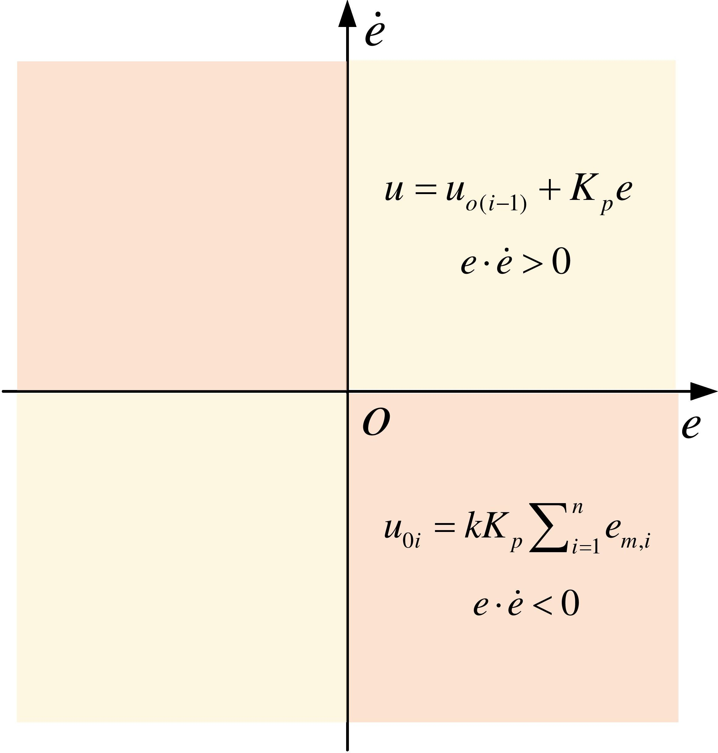
The prototype algorithm Eq. (7) first proposed the dual-mode control based on the combination of the open and closed loop and used the characteristics of the error phase plane to select and determine the control strategy online. As shown in Fig. 2, when a system error is in quadrant one or three, the controller will work in the proportional control mode; when an error is in quadrant two or four, the controller will work in the holding control mode. Paper [50] provides the details of the algorithm Eq. (7) for static and dynamic analysis.
Subsequently, with the research and development of Li et al. [63, 64, 65, 66], the dual-mode prototype algorithm evolved into a multi-mode control method combining multiple control strategies. Since the multi-mode control method can coordinate incompatible control quality requirements such as rapidity and smoothness, accuracy and robustness, it has reached high popularity. However, this approach causes chattering during mode switching. This situation is especially undesirable in practical applications.
Membrane computing (P System) is a branch of natural computing [67, 51, 68, 54, 69]. It is a computing model abstracted from the information processing cooperation of cell groups, such as cell function and structure, organs and tissues. It is an information processing inclusive space that can contain knowledge, such as control rules, and has the advantage of being easily parallelisable. This feature helps to improve the calculation speed of the controller [54]. Among the various categories of P systems, ENPSs and fuzzy reasoning spiking neural P systems are used for controller design in this paper; see [56].
ENPS
The ENPS [56, 57, 70] is a cellular P system that deals with numerical variables and allows multiple rules in each membrane. It is suitable to be used as the carrier of control rules in the design of a biped robot’s membrane controller.
The basic structure of a standard ENPS is defined as:
where,
an enzyme-free form similar to a numerical P system:
a form with enzymes:
Here,
Select rules that can be executed in each layer of the membrane structure. Combine the activated rules (freely). Operate these rules in all layers of the membrane system. Reassign the calculated value results to the defined variable object according to the value distribution rule, ending the value consumption process.
The fuzzy reasoning spiking neural P system (FRSNPS) [59, 60, 71] is a type of computational model generated by embedding fuzzy theory into P systems with the aim to solve the uncertainties faced by practical problems in the P system. It has the characteristics of direct graphic representation, parallelism, dynamics and uncertainty. Among them, ‘and’ regular neurons and ‘or’ regular neurons can be used to represent the fuzzy membership relation between input and output in fuzzy control.
The FRSNPS can be expressed as:
where,
in and out represent the set of input and output neurons, respectively.
(a) ‘And’ rule neurons; (b) ‘Or’ rule neurons.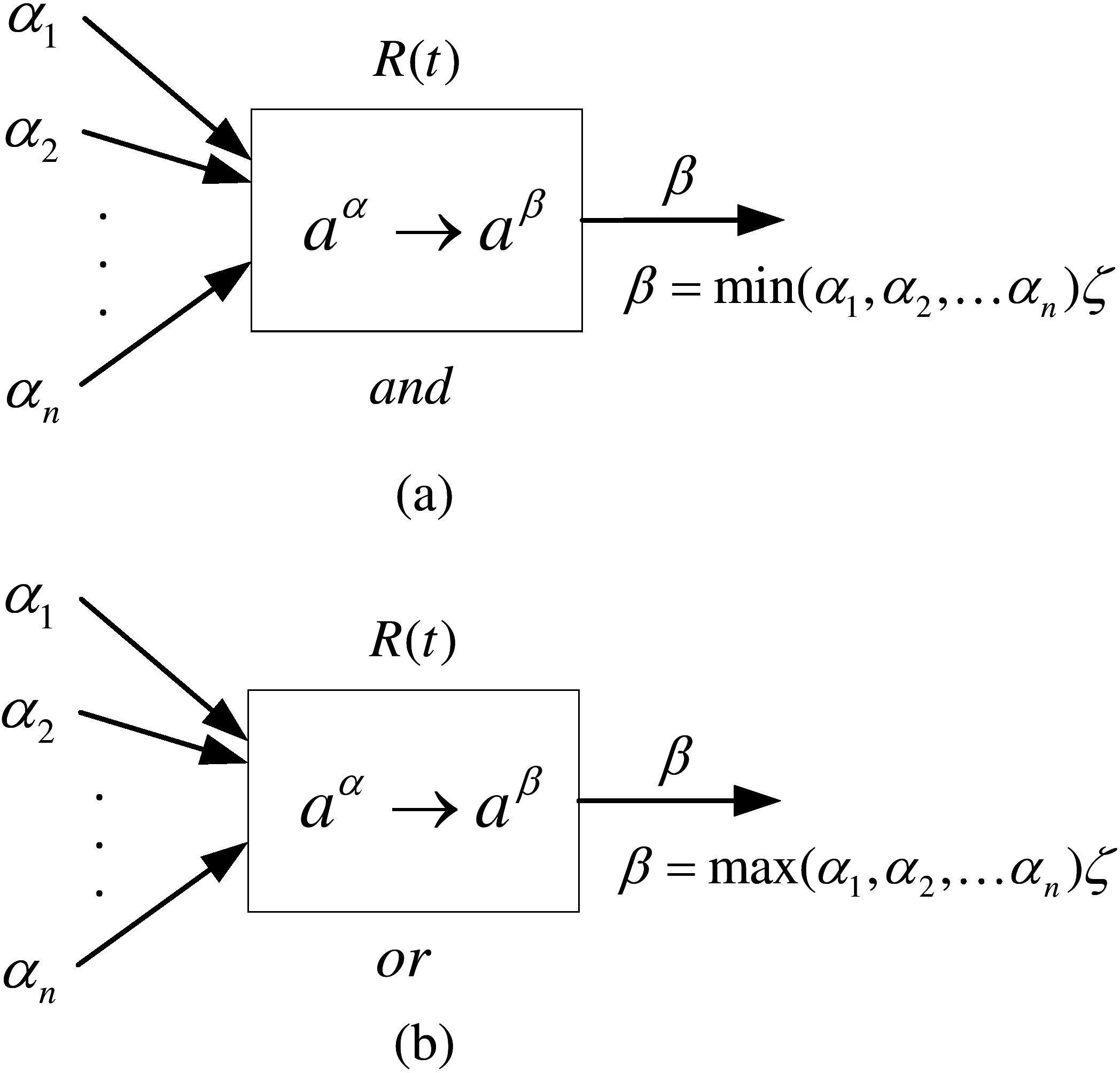
As shown in Fig. 3, (a) and (b) are conditional ‘and’ and ‘or’ rule neurons, respectively, which are used to represent fuzzy production rules with ‘and’ and ‘or’ types in fuzzy knowledge bases. The determining factor of the rule is defined as
Design of HF algorithm
As mentioned above, the joint angle of a biped robot is the controlled object, which is suitable to be controlled by HSIC with the advantages of low model dependence, high accuracy and strong robustness. Based on HSIC, the phase plane of joint angle error is designed first, as shown in Fig. 4.
The joint angle error phase plane, divided into three feature modes.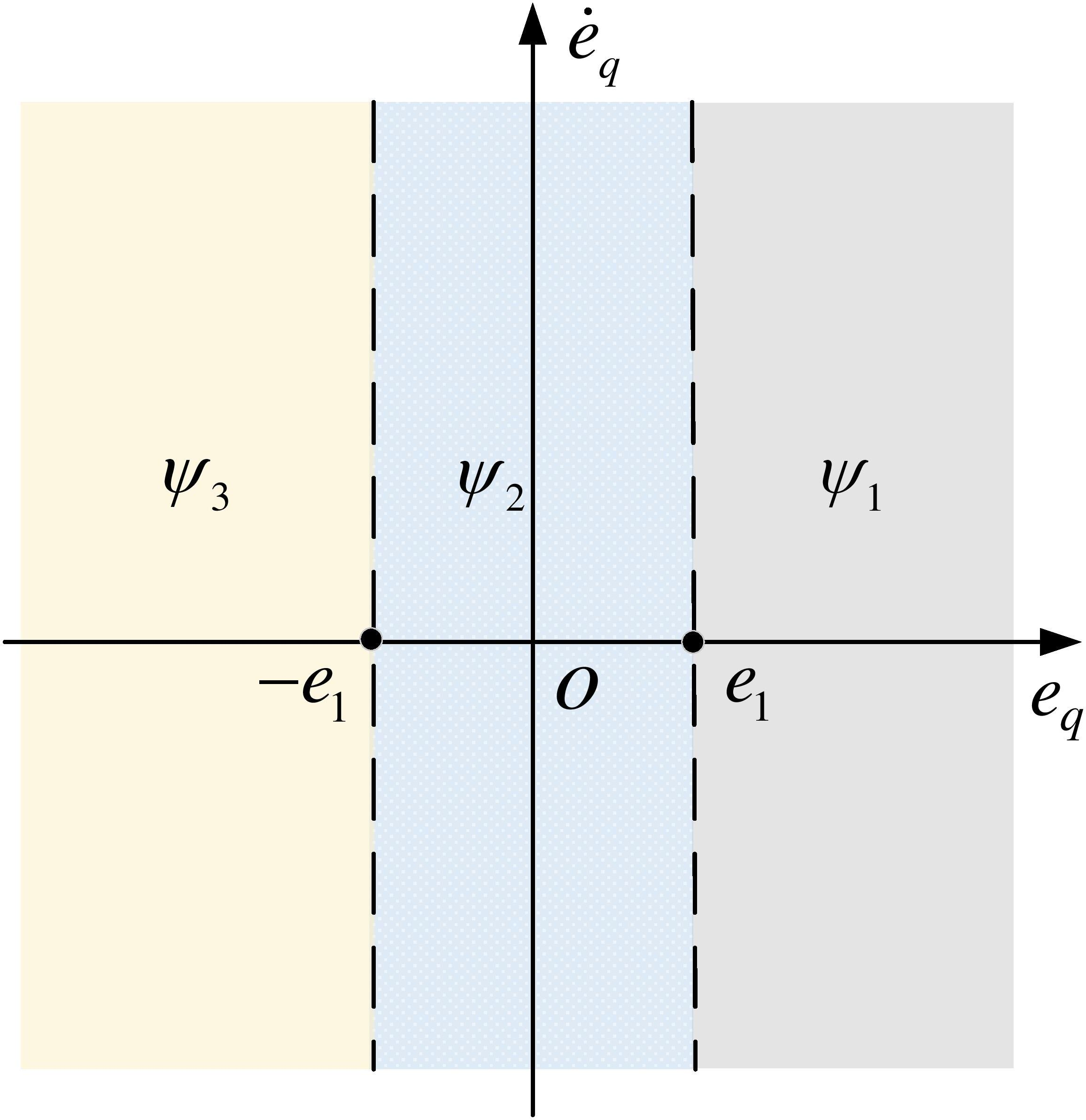
In Fig. 4,
Control law based on HSIC
In Table 1, three groups of PD coefficients are needed to set, where
In short, the selection of PD coefficients should follow the rules of
It can be seen from Fig. 4 that the three regions of the error phase plane have obvious boundaries. In contrast, while the errors and error change rates on both sides of the boundary are very small, different control strategies are adopted according to the control rules. Obviously, this control strategy is not conducive to the system’s stability, and it will make the control output chatter. Aiming to address this problem, several kinds of research on fuzzy rules to suppress the chattering of switching control have been investigated. Therefore, to obtain better control performance, the feature elements with a clear boundary are improved to fuzzy set representation, which aims to eliminate the influence of threshold boundary jump.
As shown in Fig. 5, considering the error threshold of
The joint angle error phase plane was improved by fuzzy control.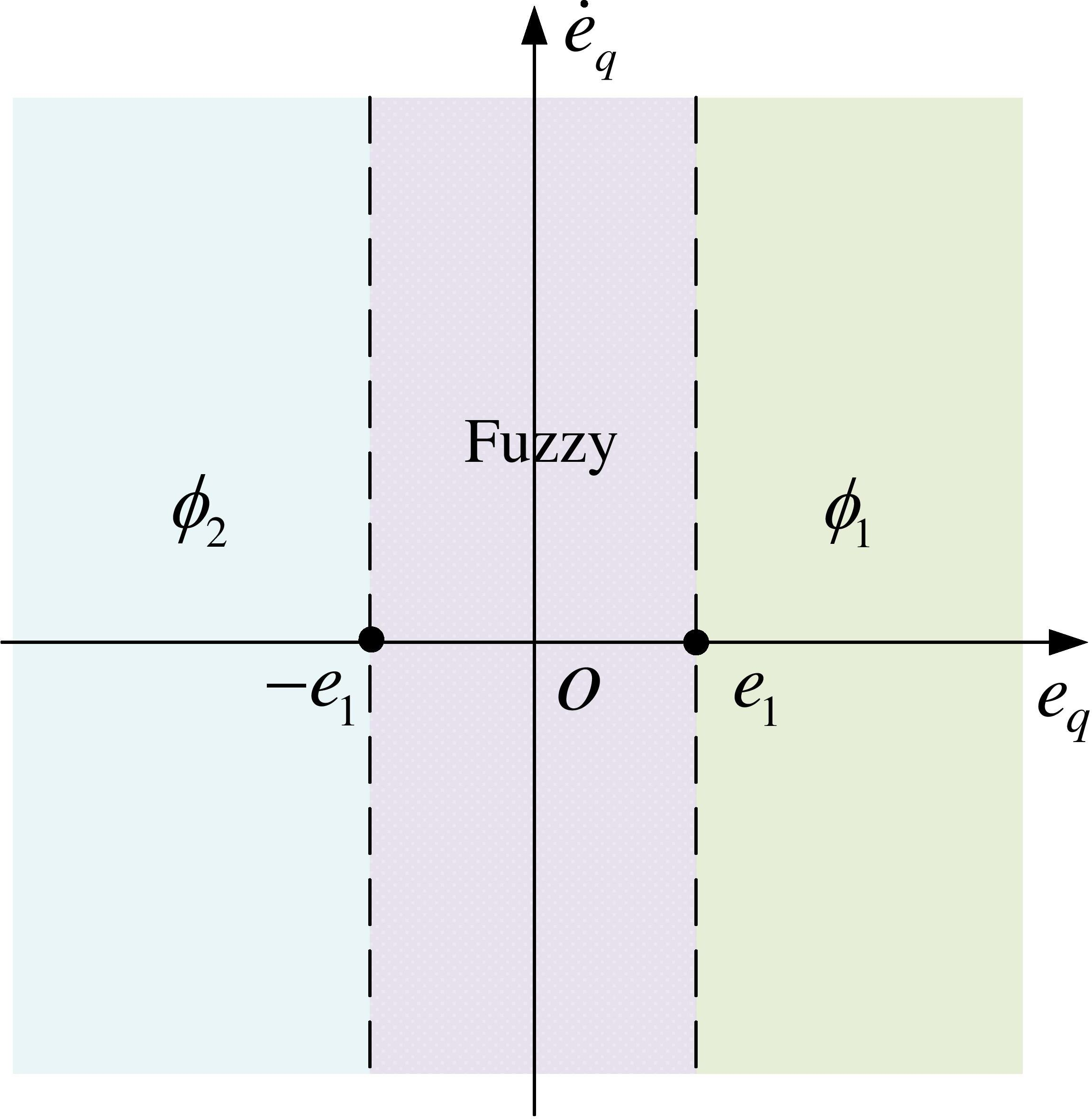
In an HFMC joint controller, ENPS is the container of the HF control rules. In the HF control rules, fuzzy control is designed by FRSNPS. The HFMC is shown in Fig. 6, and this nested membrane system accommodates control rules for three switching modes. In the HFMC, the fuzzy membrane controller (FuzzyMC) works as follows. Step 1: Membrane error (ME) and membrane error change (MEC) are parallel membranes and they can compute at the same time. After the calculation is completed, the membranes of ME and MEC are dissolved, and the results are released into the membrane of fuzzification. Meanwhile, the membrane of fuzzy_inference dissolves after the calculation is completed, and the results are released into mu_index. Step 2: the membranes of fuzzification and mu_index are parallel, they can compute simultaneously and the results are released to UF. Step 3: the membrane of UF dissolves after its calculation is completed, and the results are released into
PDMC_1, PDMC_2 and FuzzyMC are parallel relationships, and all three can compute simultaneously. PDMC_1 and PDMC_2 are similar to FuzzyMC in the computation process, and then, the three membranes dissolve and release the values into the HFMC. Ultimately, the HFMC makes the selection of control rules. In the calculation process of the membrane, it can see that the parallel relationship of membranes allows the calculation of multiple membranes to be performed simultaneously, which will save computation time.
For the convenience of design, the error
Finally, the dissolved HFMC outputs
where PDMC_1 corresponds to the phase plane
HFMC.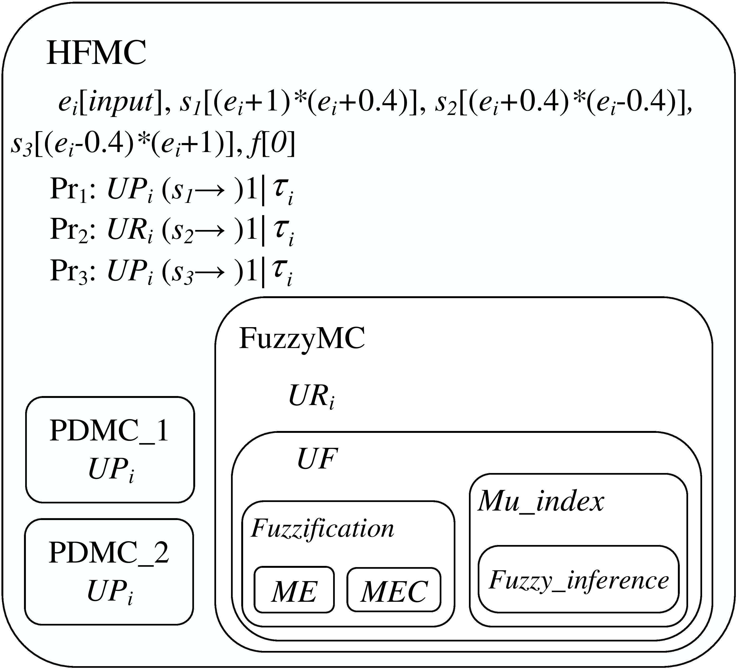
PD membrane structure.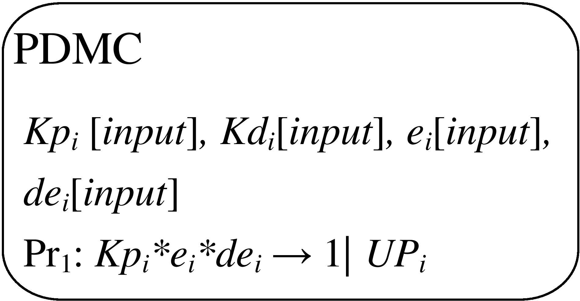
The membrane structure of fuzzification.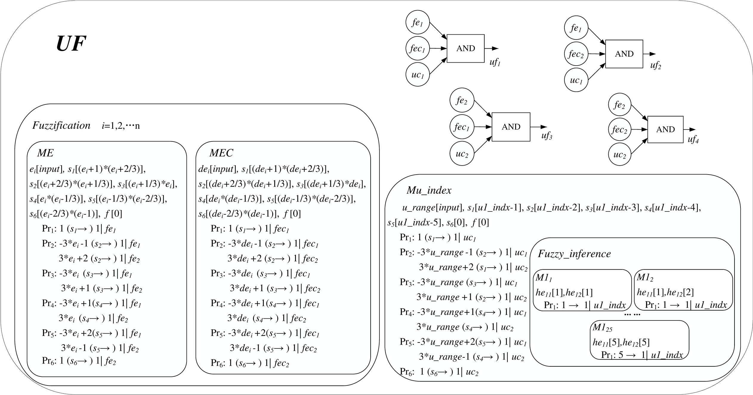
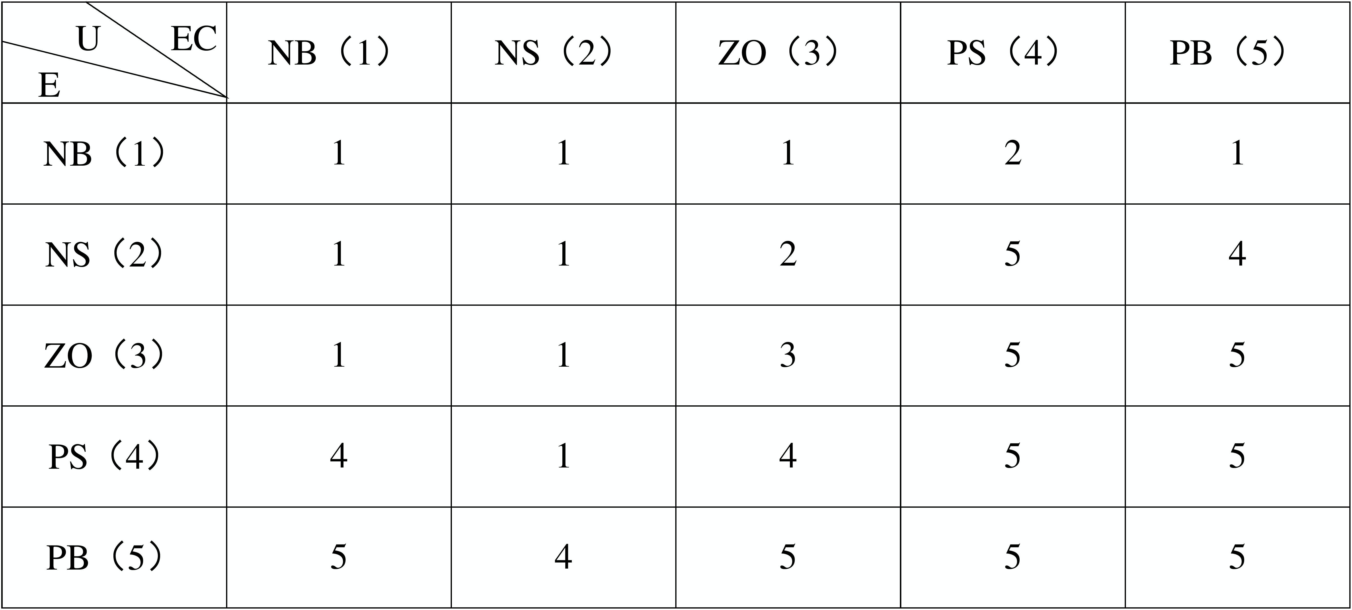
The fuzzy control rules are as follows [18]: first, the fuzzy sets of inputs and outputs are established, and the fuzzy membership are designed; second, the fuzzy control rules are established; finally, the fuzzy decisions and defuzzification are specified. Based on this control rule, in this paper, the same fuzzy sets and membership are used for both inputs and outputs (see Fig. 9).
Membership and fuzzy sets of inputs and outputs.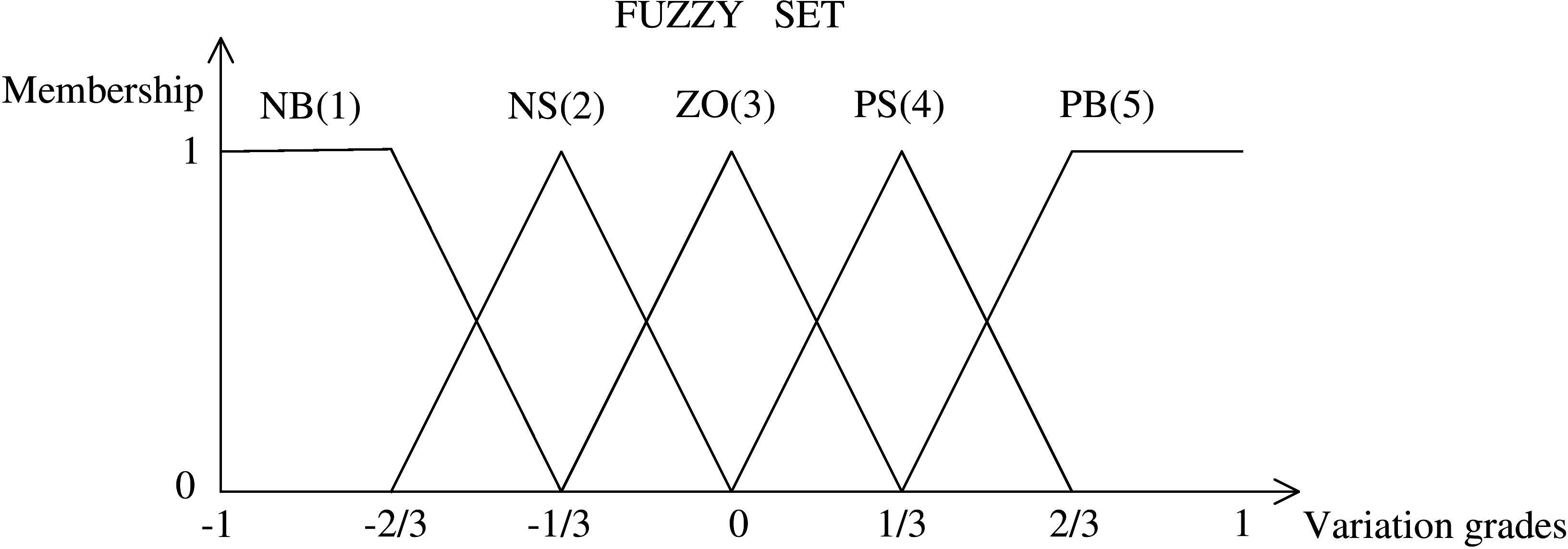
The design process of FuzzyMC is: 1) fuzzy inputting (fuzzification); 2) establishment of fuzzy control rules (mu_index); 3) formation of a fuzzy relationship UF; 4) obtainment of the fuzzy output set by fuzzy logic reasoning, and then the obtainment of accurate control output UR by the central average defuzzification method.
The UF of Fig. 8 contains two parts: one part is fuzzification for input fuzzification to establish fuzzy membership, and the other part, mu_index, is for output fuzzification to establish fuzzy membership. In fuzzification, ME and MEC fuzzify the input error and error derivative respectively and establish the membership (corresponding to Fig. 9). Meanwhile, in mu_index, fuzzy_inference establishes the fuzzy control rule (corresponding to Fig. 10), and then the fuzzy membership of the output rule is calculated by mu_index (corresponding to Fig. 9). After that, in UF, the ‘OR’ relation of input’s and output’s membership is the first step of fuzzy decision, the ‘OR’ relation in Fig. 11a is the second step of fuzzy decision and Fig. 11b is defuzzification.
In fuzzification (see Fig. 8), the input
Fuzzy control rule list.
The membrane structure of ur (a) and UR (b). In Fig. 8, ME and MEC are the solving process of membership degree of input The fuzzy_inference in Fig. 8 is the established fuzzy control rules of input and output, corresponding to 25 rules in Fig. 10. After this membrane is dissolved, the results are input to the mu_index to calculate the membership of the output. In Fig. 11a, Figure 11b is the defuzzification of

To verify the control effect of the HFMC, this paper designs the flat ground walking and slope walking simulation experiments and further compares them with PD and HSIC control methods. A five-link biped robot model (see Fig. 12) is built on Matlab R2019a based on [72]; the parameters are shown in Table 2.
Parameters of the biped robot
Parameters of the biped robot
Five-link biped robot model.
Planar and slope walking diagrams of the biped robot. (a) Planar. (b) Uphill. (c) Downhill.
Centroid velocity and displacement of slope walking. Angle tracking performance of joint 
The experimental model has four active joints and the corresponding control joint angles are
Afterwards, based on the current joint angle of the robot, the joint angle error
Experiment results
In this paper, three experiments are carried out: planar walking, uphill and downhill, as shown in Fig. 13.
Planar walking
The experiment lasted for 4 seconds, and the stability, accuracy and timeliness of HFMC control were proved by comparison with PD and HSIC. The experimental effect is illustrated by following the joint angle, joint angle error, centroid velocity and displacement, as shown in Figs 14–16.
Mean and standard deviation of joint angle error and centroid velocity (denoted as CV) error (mean
standard Deviation)
Mean and standard deviation of joint angle error and centroid velocity (denoted as CV) error (mean
Angle tracking performance of joint 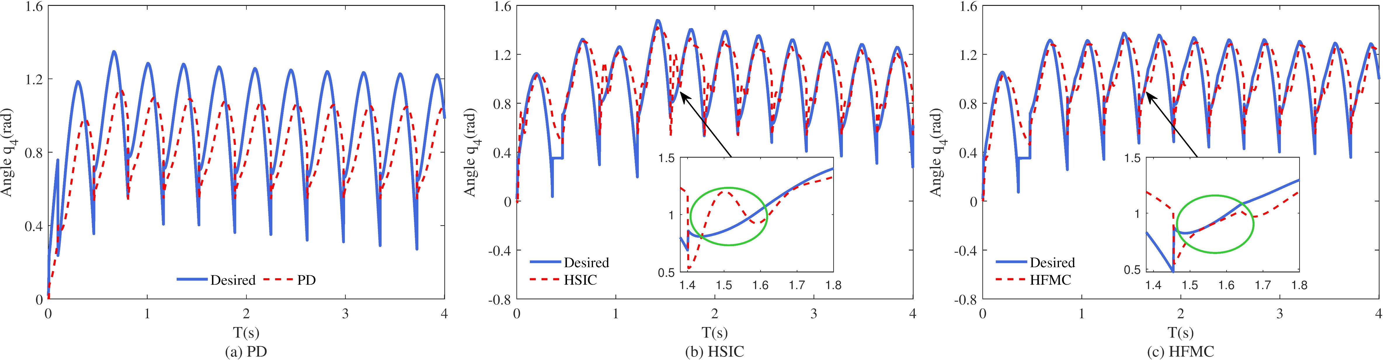
Figures 14–15 are the joint angles following the results of
In Fig. 14, it can be seen that the robot starts wobbling under PD control, while HSIC and HFMC start stably. In Figs 14c and 15, there is a control lag of PD, and the trajectory tracking effect is poor. The effect of HSIC is better than that of PD, but there is still the problem of control lag. It can be seen in Fig. 15 that the chattering is caused by the switching of the control mode of HSIC, which affects walking efficiency, while HFMC effectively inhibits the chattering. In general, the tracking accuracy and real-time performances of HFMC are optimal.
(a) Centroid velocity and (b) displacement for planar walking.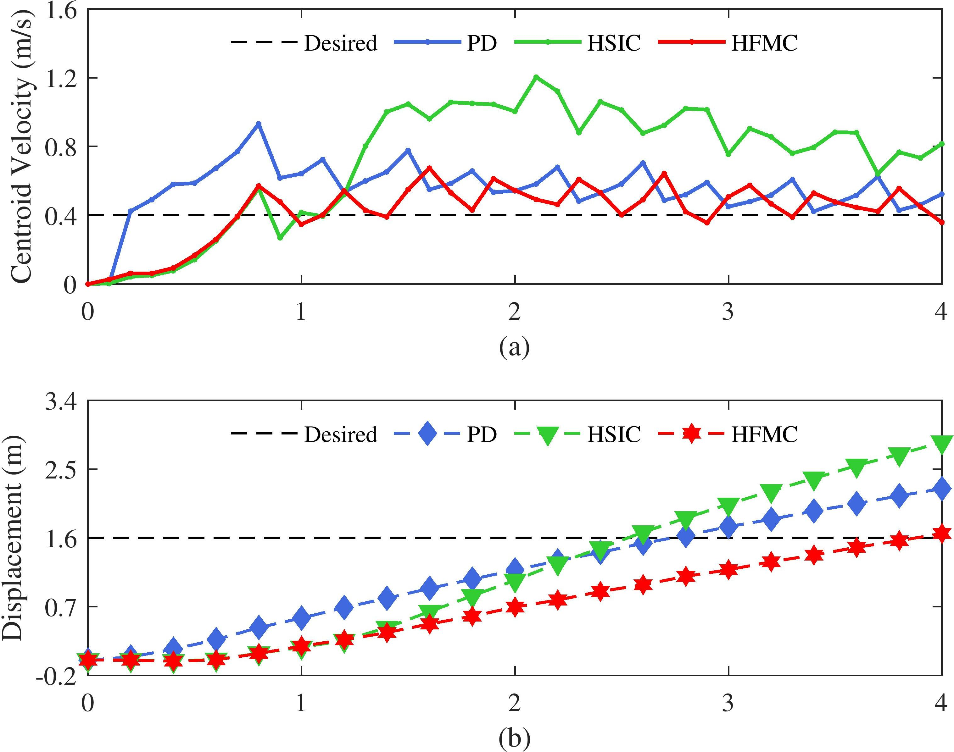
Figure 16 shows the centroid velocity and displacement. By comparison, the robot in Fig. 16a is difficult to start under PD control, and the velocity fluctuates greatly. The robot can start stably under HSIC and HFMC. However, the speed of HSIC increases after 1 s, which is far greater than the desired speed of 0.4 m/s. HFMC effectively controls the velocity within the desired speed range. As depicted in Fig. 16b, the robot smoothly reaches the desired displacement under HFMC, while PD and HSIC exceed the desired value of 1.6 m due to inaccurate speed control.
Table 3 shows the static analysis of joint angle and centroid velocity tracking errors. A comparison of the mean and standard deviation error data show that the joint angle error of HSIC is smaller than PD, while HFMC is smaller than PD and HSIC. The velocity of HSIC is the fastest, PD is the second and HFMC is the closest to the target value. The Wilcoxon test shows that the performance of HFMC is better than that of HSIC and PD.
According to synthetical evaluation, it can be concluded that the robot has a superior accomplishment under HFMC. It has good timeliness and a small joint angle following error. The robot starts stably, and the speed and displacement are controlled accurately.
This section includes both uphill and downhill experiments. The uphill experiments are carried out on a slope of 0
1) Uphill
In the uphill experiments, 90 independent runs of experiments were performed for each slope value, starting from 0
Performance of velocity, displacement and foot placement of uphill. (a–b) Centroid velocity and displacement at a slope angle of 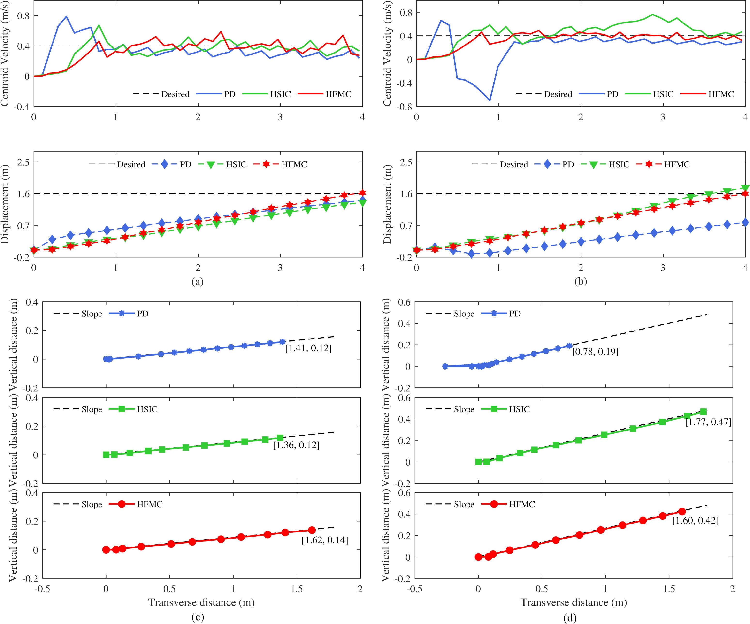
Figures 17a and 17b show the velocity and displacement of the centre of mass. In Fig. 17a, the robot’s starting speed increases rapidly under PD control, resulting in an unstable first step; HSIC is still not stable enough as the speed increases to 0.7m/s after the start and then decreases. On the other hand, the robot has a stable start and walks under HFMC. In Fig. 17b, the robot starts with a large swing under PD, which will cause the robot to fall easily. The robot starts relatively stable under HSIC, but the speed fluctuates significantly, rising to 0.8 m/s and then falling, while HFMC remains stable at the beginning and after walking.
In a comprehensive view of the displacement diagram, at 5
Performance of velocity, displacement and foot placement of downhill. (a–b) Centroid velocity and displacement at a slope angle of 
In Figs 17c and 17d, the black dotted line is the inclined plane, and the other three lines are the foot placement for the three controlled robots to walk along the inclined plane. At 5
2) Downhill
Similar to the uphill experiments, in the downhill experiments,
Figures 18a and 18b show the velocity and displacement. At
The mean centroid velocity (denoted as CV) (m/s) and displacement (denoted as D) (m) of the robot walking on the slope
In Fig. 18c, due to the fluctuation of velocity, the foot placement of PD appears uneven and smaller than the target value of [1.6,
Time (s) for PD, HSIC and HFMC on the various slope scenarios
In addition, in order to enrich the experimental results from multiple angles, the equal segment is divided with a difference of 5
To sum up, it can be ascertained that under the control of HFMC, the robot can not only walk on flat ground but also walk stably and accurately on slopes with different inclination angles under the same control parameters, which is sufficient to demonstrate the superiority of HFMC control performance.
In order to emphasise the benefits in terms of computational time of the proposed HFMC, time results are reported in Table 5.
Table 5 is the running time of a single joint controller, and it shows that HFMC outperforms, in terms of time, both PD and HSIC. These results indicate the potential of HFMC for real-time control.
The following link contains videos of the experiments and displays the effect of the various controllers under consideration on the robot’s gait:
This paper proposes a novel joint controller for biped robots, indicated with HFMC. The proposed approach combines the advantages of PD control, HSIC, fuzzy control and membrane computing. The main conclusions of this study are the following:
Chattering reduction: the multi-mode PD based on HSIC can reduce control error, but the Chattering phenomenon caused by mode switching needs to be avoided for better control. The integration of fuzzy control rules effectively solves this problem. Real-time control improvement: membrane computing has a parallel distributed structure and powerful computing power. The membrane controller HFMC combined with the control algorithm HF is a good choice to improve real-time control. HFMC retains the advantages of traditional PD, enhances the accuracy, stability and real-time of biped robot joint control and ensures excellent walking performance.
Future work will address the following issues: first, how to extend the proposed method to complex bipedal robots; second, conducting further research on HSIC and membrane computing to solve the adaptability and stability of biped robot movement in sloped, uneven and other complex environments.
Footnotes
Acknowledgments
This work was supported by the National Natural Science Foundation of China (61972324) and the Beijing Advanced Innovation Center for Intelligent Robots and Systems (2019IRS14).