
Abstract
This paper presents various aspects of propulsive performance of a dynamic azimuthing puller podded propulsor in open water condition derived from an experimental research. A model podded propulsor was instrumented to measure thrust, torque and rotational speed of the propeller, three orthogonal forces and moments, azimuthing angle and azimuthing rate of the unit. Experiments were carried out in which the azimuthing angle was varied dynamically at multiple azimuthing rates and propeller rotational speeds for different advance speeds. The model podded propulsor was capable of azimuthing or yawing continuously in the range of −180° to +180°, 0° (straight-ahead) being the design operating condition and positive azimuthing means a counter-clockwise rotation. The performance coefficients of the propeller and the pod unit showed a strong dependence on the propeller loading and azimuthing angle. The open water characteristics were mostly irregular for the astern thrust conditions in the azimuthing angle beyond the normal inflow condition and the fluctuation of the magnitude of the performance coefficients showed a considerable range. The azimuthing rate showed little or no effect on the performance coefficients in the range of azimuthing angles examined. Both at high and moderate propeller loading conditions, an increase in the shaft speed resulted in slight change in the performance coefficients and the change was more obvious as the azimuthing angle was increased. The increase in the performance coefficients due to the increase of propeller shaft speed was not noticeably affected by the change of azimuthing rate.
Keywords
Introduction
One of the attractive features of podded propulsor is that the entire unit can be rotated 360° in the horizon so as to direct the thrust vector in any direction. In dynamic azimuthing conditions, the podded propulsor with the propeller rotates about the vertical axis, z, (azimuthing) in a continuous motion at a certain azimuthing rate, while the whole pod unit moves forward at a specific advance velocity and propeller rotational speed. A study about the sources of failure [21] showed that bearings and seals were the sources of over 50% of the total mechanical failures, thus highlighting the importance of predicting bearing and other propulsion forces accurately. A thorough investigation of the hydrodynamics behind the fluctuation of the bearing forces and moments while operating in dynamic azimuthing conditions is required for a proper understanding of the issue.
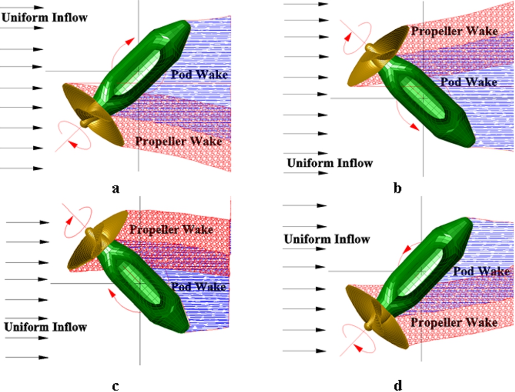
Conceptual propeller wash and pod wake at dynamic azimuthing conditions for a left-handed propeller: from top left clockwise, (a) clockwise azimuthing at the 1st quadrant (Port), (b) counter-clockwise azimuthing in the 4th quadrant (Starboard), (c) clockwise azimuthing in the 4th quadrant (Starboard), and (d) counter-clockwise azimuthing in the 1st quadrant (Port). (Colors are visible in the online version of the article;
In dynamic azimuthing conditions complex interactions between the propeller and pod-strut body is envisioned. The conceptual pod and propeller wash at different operating conditions under dynamic azimuthing is shown in Fig. 1. The figure shows the pod wake and the propeller wash due to the uniform inflow, the blade wake due to rotation and the interaction wake from the propeller and the pod. The figure shows that, the wake varies with the change of azimuthing direction as well as the angular location of the unit. At any instance during dynamic azimuthing conditions, the local inflow into the propeller blade (angle of attach at the blade) depends on three components, namely: contribution from the uniform inflow, contribution from the propeller rotation and contribution from the dynamic azimuthing. For example, in Fig. 1(a), the total inflow velocity is the addition of the contribution from the uniform inflow and the contribution from the propeller rotation with a deduction of the contribution from the dynamic azimuthing. In Fig. 1(d), the total inflow velocity is the addition of the contribution from the azimuthing, the contribution from the propeller rotation and the contribution from the uniform inflow. Thus, depending on the angular position of the pod, propeller rotation and azimuthing direction of the propulsor, the performance coefficients change even if the uniform inflow remains the same. Certainly, the propeller rotation has opposite effect on top and bottom blade pass in the opposite azimuthing position. A pod unit moving from −60° to +60° (counter-clockwise rotation) at a certain azimuthing rate and propeller rotational direction may results in different propulsive coefficients when the same unit moves from +60° to −60° (clockwise rotation), all of the kinematic parameters remains the same. These possible complex interactions between the pod-strut body and propeller with the change of azimuthing and shaft rotational directions necessitate further research on podded propulsor performance at various dynamic azimuthing conditions.
There are hardly any recently published works that address the behaviour of podded propulsors at dynamic azimuthing angles. Stettler [21] in his doctoral work investigated steady and unsteady dynamic manoeuvring forces associated with an azimuthing podded propulsor, and also provided supporting theoretical insight toward understanding their mechanisms and prediction. The work included quasi-steady vectored manoeuvring forces, as well as unsteady or transient manoeuvring forces. Akinturk et al. [1] presented results and analyses of an experimental study into the effects of static and dynamic azimuthing conditions on the propulsive characteristics of a puller podded unit in open water. The author presented results of pod performance in the range of −180° to 180° in static and dynamic azimuthing conditions for one propeller loading condition and azimuthing rate. The paper raised some interests amongst the readers on the effect of azimuthing direction, rate and shaft speed on the propulsive characteristics of pod in dynamic azimuthing conditions. The study presenting the effect of azimuthing direction and rate and propeller rotational speed on the pod performance has never been published.
The current work was the most recent part of a research program on podded propulsor performance. Amongst the hydrodynamic issues affecting performance that have been identified in the research program are questions regarding the effects of hub taper angle [14], pod-strut configuration [8], pod-strut interactions [6], and pod-strut geometry [16], pod gap [13], static azimuthing conditions [12] and scale effect on pod [11].
In the current study, a scale factor of 15.9 was used to design the model and experimental setup. The open water tests in dynamic azimuthing conditions were performed in accordance with the ITTC recommended procedure, Podded Propulsor Tests and Extrapolation [17], and the description provided by Mewis [19]. The tests were performed using a custom-designed dynamometer and pod system [10]. The pod unit with the propeller was rotated about the vertical axis passing through the centre of the strut in a continuous motion as the whole test unit moved forward with specific advance and propeller shaft speeds. The propeller and unit performance were measured and analyzed at dynamically varying azimuthing angles and rates under different operating conditions. The pod dynamometer system measured propeller shaft thrust (T), propeller shaft torque (Q), unit axial force (
Typically, a full scale podded propulsor azimuths at a rate of 2.5°/s at the vessel’s service speed, requirement from the SOLAS, [20]. During manoeuvring at slow speeds where less torque is required than in the full speed mode, the azimuthing rate is approximately 5°/s. Depending on the ratio of the maximum vessel speed to the maximum steering torque at the lower speeds, manoeuvring at 12°/s azimuthing rate can be considered as a special case [5]. With the scale factor of 15.9 and using the Froude scaling, the corresponding model scale azimuthing rates are 10°/s, 20°/s and 48°/s. For the present dynamic azimuthing study, the experiments were conducted at the model scale rates of 2°, 5°, 10°, 15° and 20°/s with azimuthing angles between 0° and ±60°, 0° being the straight-ahead condition. An azimuthing rate higher than 20°/s could not be achieved due to limitation of the instrumentation. These measurements were taken at propeller shaft speeds of 15 rps and 8 rps. Additionally, pod performance parameters were measured for azimuthing angles from −180° to +180° at 10°/s dynamic azimuthing rate. All of these measurements were made at different advance coefficients ranging from
Test matrix for systematic dynamic azimuthing podded propulsors’ tests
Test matrix for systematic dynamic azimuthing podded propulsors’ tests
The selection of propeller shaft speed and azimuthing rate was primarily done to evaluate their individual effects on the hydrodynamic performance of the pod unit in dynamic conditions. Investigating the phenomena like visible oscillations (resonance) at high turning rates, i.e. propeller shaft speed closer to azimuthing rat, was not within the scope of the present work. The authors understand that if the shaft rotational rate of the propeller and azimuthing rate of the pod unit are of the same ratio, interesting phenomena may occur. However, during the experimental design phase, emphasis was not given to study this phenomenon. Coincidently, there was one case where the propeller shaft rotational rate (15 rps) was equal to pod unit azimuthing rate (15°/s) but this did not show any resonance issue, see Section 3.4 for details. Note, the vortex shedding behind the strut at azimuthing condition was not analyzed as it was outside the scope of the current program. The instrumentation used was not sensitive enough to accurately measure the effect of vortex shedding from the strut.
The experiments included tests on a model propeller with a pod unit consisting of a pod shell and a strut. The propeller had a hub taper angle of −15°. The propeller was a left-handed propeller. The propeller was made of bronze and the skeleton of the pod unit was made of steel. The pod shell was made of ranshape. A description of the propeller characteristics is provided in Table 2. Details of the geometry of the propellers are presented in [18]. The geometrical particulars of the pod unit (pod-strut and the propeller) used in the dynamic azimuthing tests are shown in Table 3.
Geometric characteristics of the propellers used in the current study
Propeller and pod dimensions used in the current study
The experiments were performed using a custom-designed dynamometer and pod system. The equipment has two major parts: the pod dynamometer measures the thrust and the torque of the propeller at the propeller shaft very close to the hub, and the global dynamometer measures the unit forces and moments in three coordinate directions. Further details of the apparatus and the boat can be found in [10]. The tests were performed in the 200 m long Ocean, Coastal and River Engineering (OCRE-NRC) towing tank. The carriage is designed with a central testing area where a test frame, mounted to the carriage frame, allows the experimental setup to move transversely across the entire width of the tank. Figure 2 shows the pod dynamometer system installed in the towing tank facility.
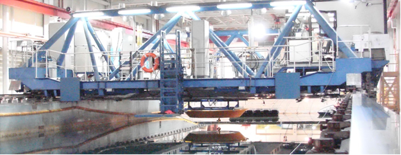
The pod dynamometer system installed in the towing tank facility. (Colors are visible in the online version of the article;
The global dynamometer was calibrated by using the method described in [7] and [5]. The definition of the forces, moments and co-ordinates that was used to analyze the data and present the results is shown in Fig. 3. A right handed coordinate system with positive Z downward is used for the carriage fixed system. The coordinate centre was situated 0.5 m vertically above the pod centre, which is at the intersection of the horizontal axis through the propeller shaft centre and the vertical axis through the strut shaft centre. Looking from top, a counter-clockwise rotation of the pod unit provides a positive azimuthing angle. The propeller forces, pod unit forces and moments are presented in the form of traditional non-dimensional coefficients as defined in Table 4.
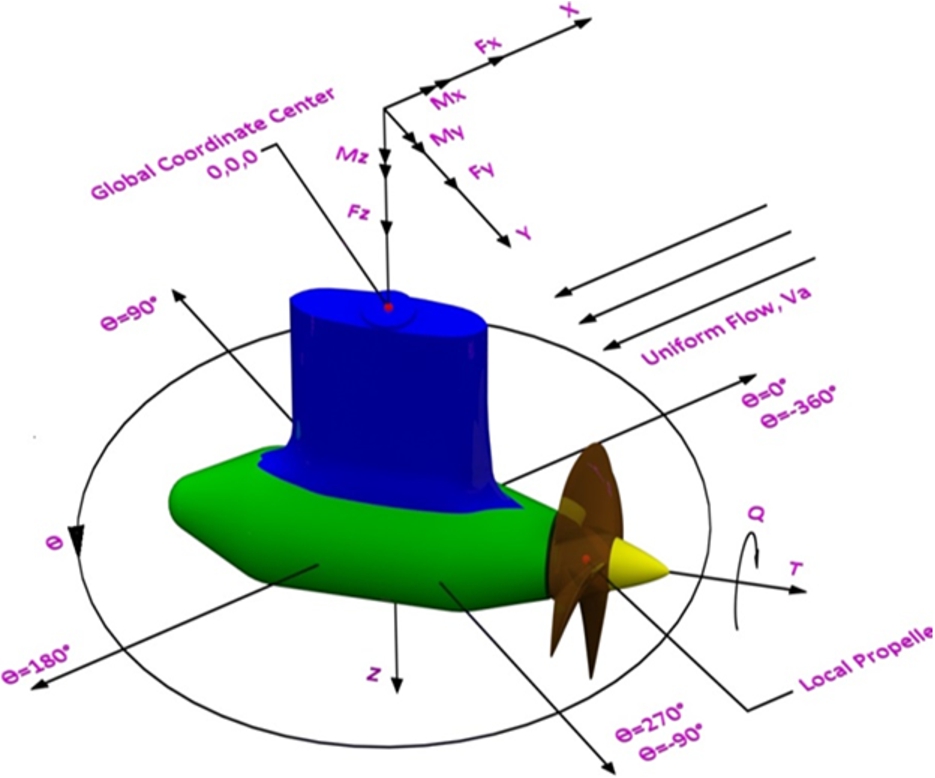
Definitions of forces, moments, coordinates of the puller azimuthing podded propulsors. (Colors are visible in the online version of the article;
Data reduction equations and definitions of parameters used to present the experimental data
Notes: T – propeller thrust; Q – propeller torque; ρ – water density; n – propeller rotational speed; D – propeller diameter;
The purpose of the model and the basin size generally determine the size of a propulsor model. It is often difficult to make a large propeller, pod housing and strut for such an azimuthing model experiments, due to the load limits of all the sensors, especially the thrust and torque sensors. The current pod model was designed for a twin-screw ship model. The authors realize that the propeller model was on the small side of the ITTC recommended sizes, even if it was tested at 15 rps of shaft rotational rate. In order to confirm minimum scaling effect, Reynolds Number dependent experiments were carried out at the beginning of this research program. Also, static azimuthing experiments were carried out with two separate units of different sizes (200 mm and 270 mm propellers), which are presented in [11]. It was concluded in [11] that the propulsive performance of the small propeller stabilizes at lower Reynolds Numbers than the large propeller. No significant effect of scale was evident for propeller thrust and torque. However, the variations of the unit force and moment coefficients with the change of propeller size for varied azimuthing conditions were very evident, which was attributed to the flow condition that prevails around the pod-strut body [11]. The propeller size may be more important for the measurements at small azimuthing angles when the flow is not fully separated, hence not fully turbulent. At large azimuthing angles, however, the flow starts to separate, which means the flow become fully turbulence. In such case, the Reynolds Number effect minimizes as the flow over the model propulsor becomes close to a full scale propulsor. Discussions on the effect of shaft speed, hence the Reynolds Number on the pod performance in dynamic azimuthing conditions are presented in Section 3.5.
In the dynamic azimuthing tests, the measurements were taken of the forces and moments acting on the propeller and the whole pod unit at different advance coefficients, and at different dynamic azimuthing rates. The data was acquired at a sample rate of 5000 Hz. When hydrodynamic tests are carried out up to a certain high frequency, it is often a challenge to separate the system response from the hydrodynamic excitations. This may be the case for the present dynamic model tests for the azimuthing propulsors. Correctly simulating the response of podded arrangement and driving system is essentially important for the measured data. Within those responses, the shaft torsion, bending and the gear meshing excitations during the model tests are the most relevant issues. Correctly simulating the structure and mechanical responses in model scale is extremely difficult. In order to separate the system response, carriage response and gear meshing excitations from the dynamic loads, pluck (hammer) experiments were carried out to find out the natural frequencies of the pod system as well as of the carriage. These effects were taken out in the presented data set using the Fast Fourier Transform (FFT) filtering technique.
In the FFT analysis, the signals for each of the measurements were decomposed to obtain the power spectrum in the frequency domain. After closely reviewing the spectrum, the high frequency noise (non-hydrodynamic) signals were removed from the original signal by filtering the Fourier transform of the signal, then using the inverse Fourier transform to reconstruct the signal. In the current analysis, each of the signals were filtered at 7.5 Hz to make sure the noise due to the system response, carriage response and gear meshing are removed from the pure hydrodynamic loads. The natural frequencies of the pod system and of the carriage were determined to be 15.8 Hz and 10.2 Hz, respectively. A properly designed measurement system would have a time constant less than 0.1 s. Note FFT based filtering actually removed the unwanted noise due to system and the carriage from the measurement; the accurateness of the obtained measured data was not compromised in this process.
When dynamic model tests are concerned, the mass and mass moment of inertia can become important. The material used for the propeller was bronze. It is generally recommended to make the propeller with light material so that the inertia cannot play any role to influence the system dynamics. To evaluate the effect of inertia (centrifugal effect), in-air dynamic azimuthing experiments (dynamic azimuthing in air at different azimuthing and propeller revolution rates) were carried out only to find out that the inertia effect was negligible. Note, the inertia effect in water might be slightly different and should be accounted for in future investigations.
Measurement repeatability in dynamic conditions
The first set of experiments involved the repeatability check of the measurements in dynamic azimuthing conditions in the range of −60° to +60° at different azimuthing rates. At least three repeats were completed at advance coefficient,
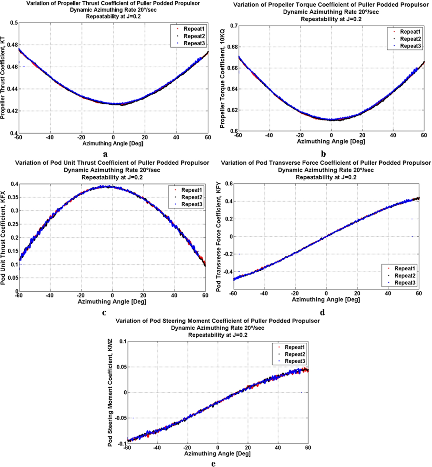
Repeatability of measurements on propulsive performance of the model pod unit in dynamic azimuthing conditions: (a) propeller thrust, (b) propeller torque, (c) pod unit thrust, (d) pod unit side force, and (e) pod unit steering moment. (Colors are visible in the online version of the article;
An azimuthing rate of 10°/s was used in this part of the study. The comparison was made at advance coefficient value of 0.2 and 0.5. In each of the figures in this section, black line represent the dynamic azimuthing data at
Figure 5(a) through (e) show a comparison of the propeller and pod unit performance characteristics at dynamic azimuthing condition in the azimuthing range from −180° to 180° at advance coefficient of

Effect of propeller loading on propulsive performance of the model pod unit in dynamic azimuthing conditions: (a) propeller thrust, (b) propeller torque, (c) pod unit thrust, (d) pod unit side force, (e) pod unit steering moment. (Colors are visible in the online version of the article;
Note, the unit thrust coefficients decreased for both azimuthing directions but the reduction was visibly stronger for positive azimuthing angles. A similar trend was found for all advance coefficients and within the range of azimuthing angles of ±90°. The unit thrust coefficients increased as the azimuthing angle was increased further beyond ±90°. When azimuthing in the negative direction, with a left hand propeller, the total inflow velocity in the addition of the contribution from the uniform inflow and the azimuthing direction with a deduction of the contribution from the propeller rotation. However, when azimuthing in the positive direction, the total inflow velocity in the addition of the contribution from the uniform inflow and the propeller rotation with a deduction of the contribution from the dynamic azimuthing; see Fig. 1. Essentially, the contribution from propeller rotation is higher than that of the dynamic azimuthing, which results in higher local inflow velocity for the positive azimuthing case. This can be the attributed to the higher reduction in unit thrust in the positive azimuthing direction. Section 1 presents a further discussion on this phenomenon.
The asymmetric characteristics of all the forces and moments with respect to the azimuthing angle may be attributed to the direction of rotation of the propeller and the unit, the azimuthing rate and possibly to the typical dynamic effects known as the ‘hysteresis effect’. When the podded propulsor is turning from −180° through 0° to +180°, the measured forces and moments will be different from that when turning the pod from +180° through 0° to −180°. The angle of attack at the blades changes with the change in azimuthing rate and direction, see Fig. 1. The hysteresis effect, if any, will be more pronounced on the unit forces and moments, but less pronounced on propeller forces and moments. The present research incorporated this study within the range of azimuthing angle of ±60° and is discussed below.
The propeller thrust and torque and pod unit thrust, side force and steering moment, in Fig. 6(a)–(e), were affected by the azimuthing direction in the range of −65 through 0° to +65°, both at advance confidents of
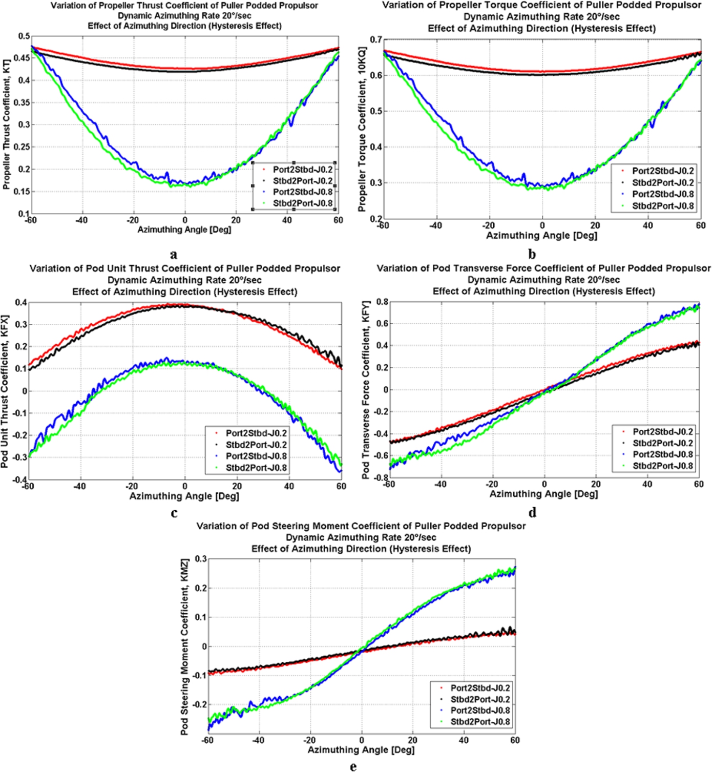
Effect of azimuthing direction (hysteresis effect) on propulsive performance of the model pod unit in dynamic azimuthing conditions, from top left clockwise: propeller thrust, propeller torque, pod unit side force, pod unit steering moment and pod unit thrust. (Colors are visible in the online version of the article;
The experimental study into the effect of azimuthing rate on the propeller and unit forces and moments at dynamic azimuthing conditions within the range of +60° to −60° was carried out for two advance coefficients of
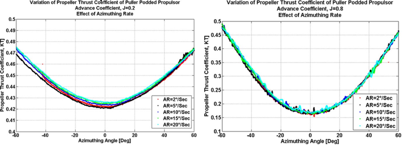
Effect of azimuthing rate on propeller thrust coefficient of the model pod unit in dynamic azimuthing conditions at advance coefficients of

Effect of azimuthing rate on propeller torque coefficients of the model pod unit in dynamic azimuthing conditions at advance coefficients of
For propeller thrust and torque coefficients, as shown in Figs 7 and 8, respectively, the azimuthing rate did not have any noticeable effect when the azimuthing rate was equal to or higher than 5°/s for positive azimuthing angles. This was observed for both advance coefficients. However, at the negative azimuthing angle, especially for
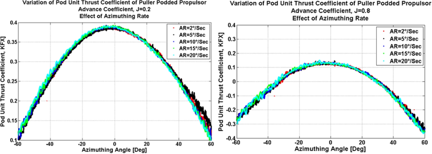
Effect of azimuthing rate on pod unit thrust coefficient of the model pod unit in dynamic azimuthing conditions at advance coefficients of

Effect of azimuthing rate on pod transverse force coefficient of the model pod unit in dynamic azimuthing conditions at advance coefficients of
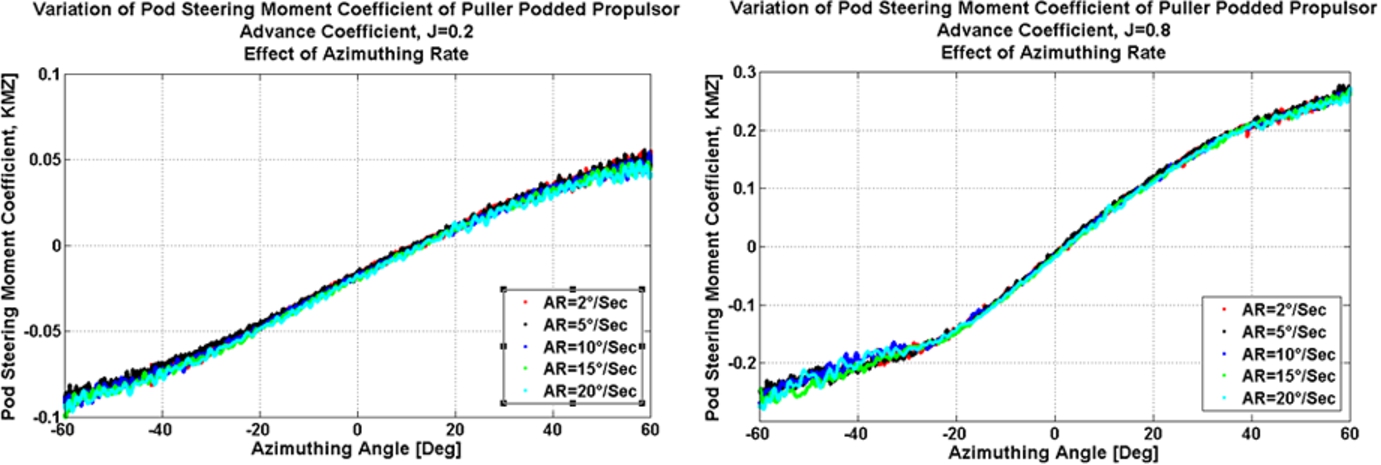
Effect of azimuthing rate on pod unit steering moment coefficient of the model pod unit in dynamic azimuthing conditions at advance coefficients of
The study of the effect of propeller shaft speed on the performance coefficients at different azimuthing rates and advance coefficients at dynamic azimuthing conditions is presented in this section. The study was carried out at two propeller shaft speeds of 8 and 15 rps and at the advance coefficients of
The propeller and pod the unit performance coefficients at the two shaft speeds with various azimuthing rates and advance coefficients are shown in Figs 12–16. It is observed that at both advance coefficients of 0.2 and 0.8 as the shaft speed was increased from 8 rps to 15 rps, the performance coefficients changed slightly.
The change of the performance coefficient values with the increase of propeller shaft speed can be attributed to three factors, namely: Reynolds Number, the added mass effects, and the measurement errors. The Reynolds Number based on the propeller blade chord length at 70% of the radius at the propeller speeds of 15 rps and 8 rps varied between
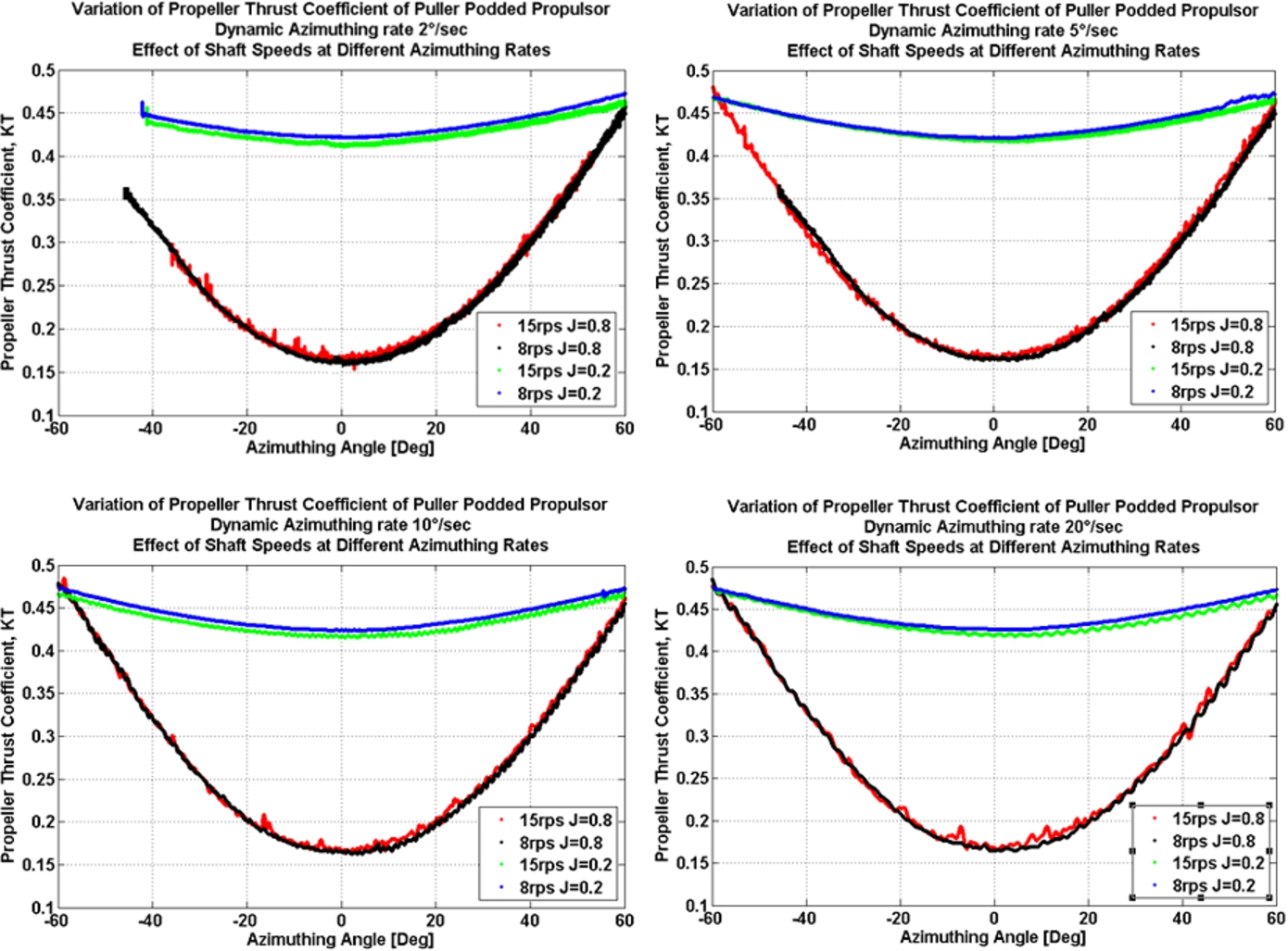
Variation of propeller thrust coefficient of the model pod unit with shaft speed and azimuthing rate in dynamic conditions. (Colors are visible in the online version of the article;
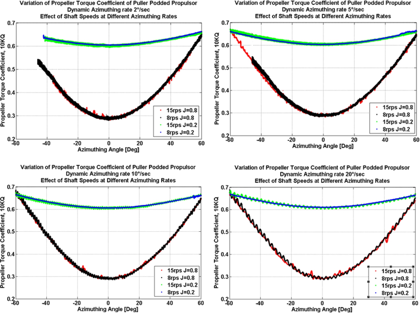
Variation of propeller torque coefficient of the model pod unit with shaft speed and azimuthing rate in dynamic conditions. (Colors are visible in the online version of the article;
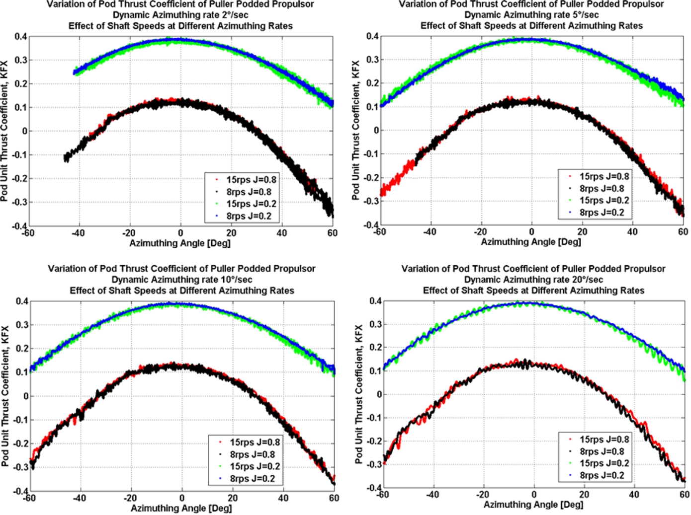
Variation of unit thrust coefficient of the model pod unit with shaft speed and azimuthing rate in dynamic conditions. (Colors are visible in the online version of the article;
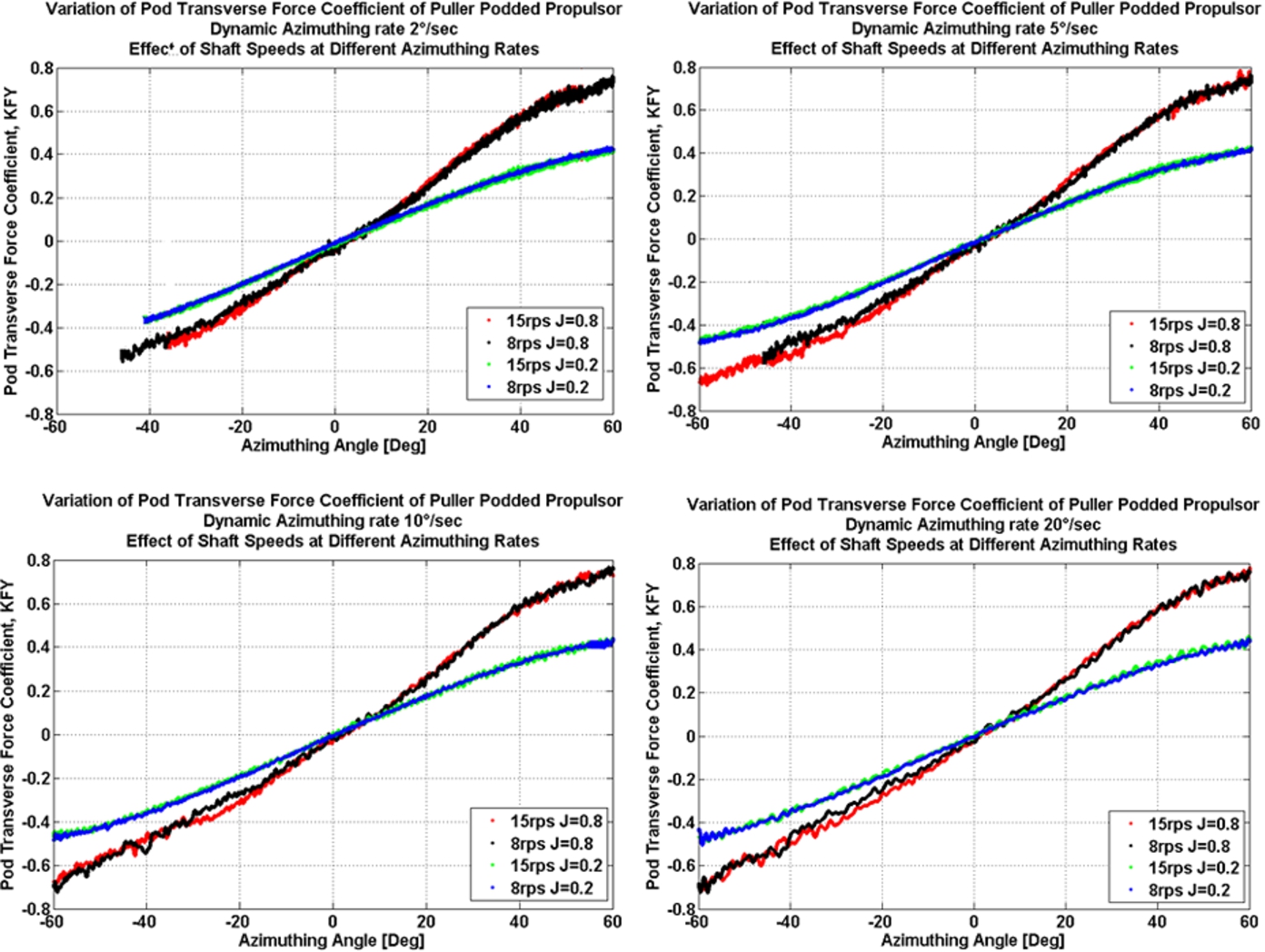
Variation of transverse force coefficient of the model pod unit with shaft speed and azimuthing rate in dynamic conditions. (Colors are visible in the online version of the article;
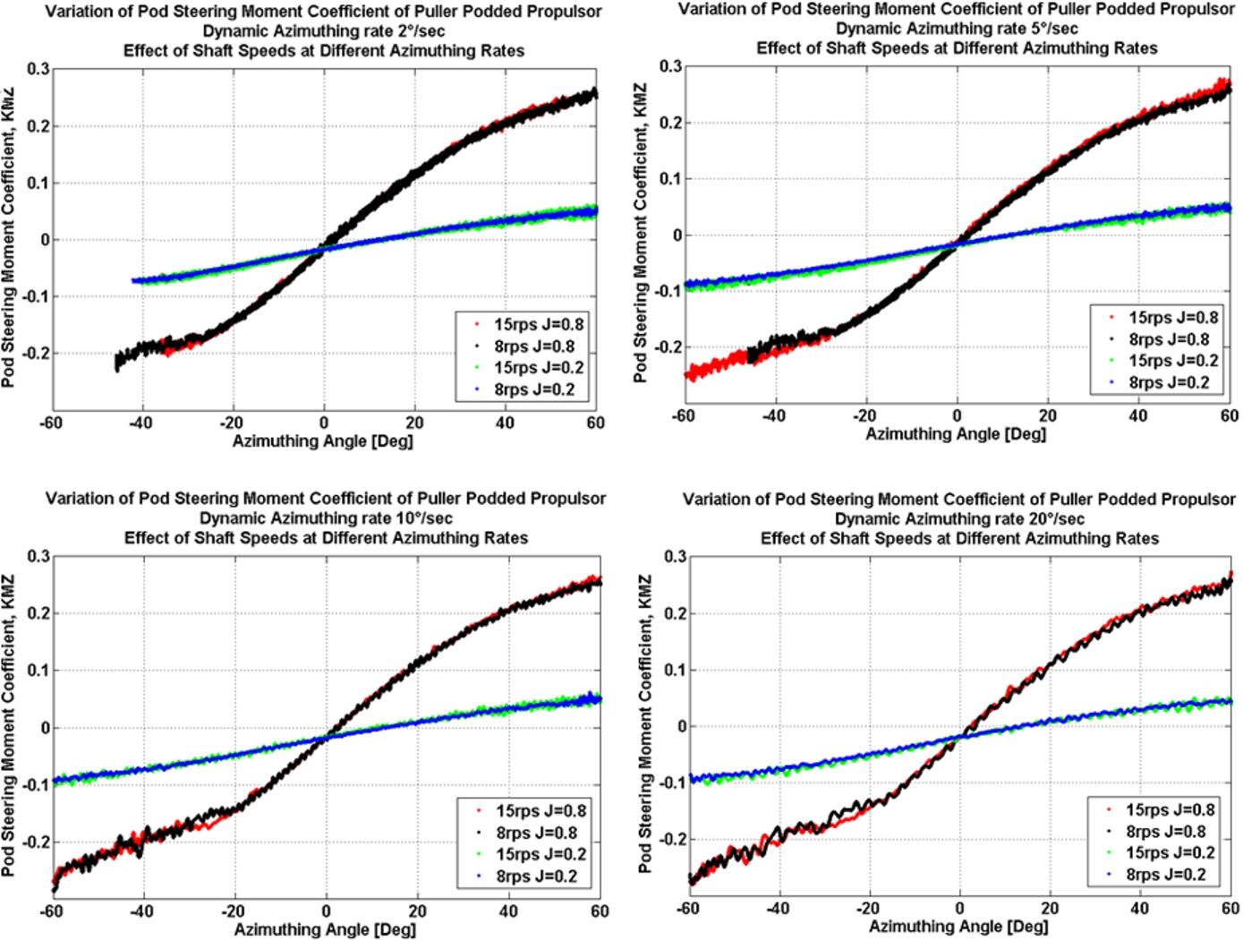
Variation of steering moment coefficient of the model pod unit with shaft speed and azimuthing rate in dynamic conditions. (Colors are visible in the online version of the article;
A brief discussion of the levels of uncertainty in the above results is given below. To assess the uncertainty in each set of experiments and to identify the major factors influencing these results, a thorough uncertainty analysis was conducted [9] and [15]. The techniques used were based on adaptations of uncertainty analysis techniques outlined in [2,10] and [4]. The dynamic nature of the experiments was not considered in the analysis.
The overall uncertainty in the non-dimensional performance coefficients of the podded propulsors required proper identification of all the variables contained within the data reduction expressions [4]. The experimental approaches used to obtain the data for each of the variables in the expressions were influenced by a variety of elemental sources of error. These elemental sources were estimated, and combined using the root-sum-square (RSS) method to give the bias and precision limits for each of the variables. The error estimates used in the determination of the bias and precision errors in this study were considered to be 95% coverage estimates. The bias uncertainty and the precision uncertainty were combined using the root-sum-square (RSS) method using the following equation to provide estimates of overall uncertainty levels in these variables. The overall uncertainty was thus considered to be a 95% coverage estimate. The resulting error estimates for the podded propulsor tests are given in Table 5:
Overall uncertainties (in percentage terms) in advance coefficient, propeller thrust and torque coefficients and pod unit thrust, transverse force and steering moment coefficients for the podded propulsor
Overall uncertainties (in percentage terms) in advance coefficient, propeller thrust and torque coefficients and pod unit thrust, transverse force and steering moment coefficients for the podded propulsor
The primary element of the uncertainty of the propeller performance coefficients was the bias error (90% or more of the total uncertainty for the pod dynamometer system). To reduce the overall uncertainty in the final results, the primary focus should be to reduce the bias error in the equipment. However, for the global performance coefficients, generally, the primary element of the uncertainty was precision error (about 60% or more of the total uncertainty). The uncertainty analysis results provided strong evidence that the experimental data obtained using the pod dynamometer system presented the true performance characteristics of the model scale podded propulsors under consideration.
An experimental study of shaft thrust and torque, unit thrust and transverse force, and steering moment, of a model puller podded propulsor at different dynamic azimuthing conditions and advance coefficients was undertaken in open water conditions. A custom made dynamometer system was used to measure forces and moments of the pod unit at different dynamic azimuthing conditions in the range of −180° to 180° azimuthing positions. The results supply some fundamental information with respect to manoeuvring loads from the pod and dynamic behaviour of the pod loads.
The propeller thrust and torque coefficients of the puller propeller increased when the azimuthing angles were increased from straight-ahead condition (0° angle) both in positive and negative azimuthing angles. The maximum propeller coefficients were observed at the azimuthing angles of ±120°. There was some scatter at the large azimuthing angles, which can be attributed to the unsteady nature of the reverse wash and separation (at azimuthing angles greater than ±90°). The data at different advance coefficients clearly show regular non-linear trends, which can be associated with the changing wake characteristics as the azimuthing angle changes. Small asymmetries in location and magnitude of the maxima might be due to the influences of propeller rotation direction and the interaction between the propeller wash and the pod-strut body. Propeller thrust and torque coefficient showed similar trends at corresponding azimuthing angles and advance coefficients.
The unit thrust coefficients decreased for both azimuthing directions but the reduction was visibly stronger for positive azimuthing angles. A similar trend was found for all advance coefficients and within the range of azimuthing angles of ±90°. The unit thrust coefficients increased as the azimuthing angle was increased further beyond ±90°. The transverse force coefficient of the propulsor with left-handed propeller showed strong dependency on propeller loading and azimuthing angle. The nature is similar to that of a classical rudder. For all advance coefficients, the transverse force coefficients increased with both positive and negative azimuthing angles from straight-ahead condition. The maximum transverse force coefficient was found in the range of ±60° to ±90°. The steering moment coefficient showed nonlinear changes with advance coefficients and azimuthing angle. The steering moment coefficient increased with the larger azimuthing angles up to ±90°. For further increase in azimuthing angle up to ±180°, a decrease in steering moment was observed. These were observed for all advance coefficients except at the bollard pull condition.
The fluctuation of the magnitude of the performance coefficients for the advance coefficient showed a considerable range and care should be taken while designing the propeller and pod bearings, which would be subjected to the fluctuating forces.
The azimuthing rate did not show any conclusive effect on the performance coefficients in the range of azimuthing angles from +60° to −60°. The slight difference in the performance coefficients with the change of azimuthing rate that was observed, especially in the azimuthing range of 0° to −60° was within the limit of uncertainty bar, hence was not significant.
The propeller and the unit performance coefficients changed slightly but inconsistently with the change of propeller shaft speeds. The change in the performance coefficients due to the increase of propeller shaft speed was not noticeably affected by the change of azimuthing rate. The minor difference in the performance coefficients due to the change in the propeller shaft speed might be attributed to measurement error. This demonstrates that the propeller size was sufficiently large to have minimal Reynolds Number effect on the experimental data.
The uncertainty analysis results provided strong evidence that the experimental data obtained using the pod dynamometer system presented the true performance characteristics of the model scale podded propulsors under consideration. It is demonstrated that the pod apparatus can replicate the measurement in the dynamic azimuthing conditions in the rage of −60° to +60° within acceptable accuracy.
Footnotes
Acknowledgements
This study on podded propellers is a joint project between the National Research Council of Canada, Transport Canada and Memorial University. The authors are indebted to Oceanic Consulting Corporation for allowing time and resources to complete the analysis and presentation of the paper. Special thanks are extended to the members of Design and Fabrication and Experimental Facilities at the National Research Council of Canada’s Ocean, Coastal and River Engineering.