
Abstract
In the process of marine salvage, the capsized ship is normally required to go through a process of righting firstly, which essentially means bringing the deck to point upwards. Calculation of the righting force is the key to achieving success in designing schemes. At present, the righting force calculation relies on the use of empirical formulae. However, their accuracy and reliability is not high. In this paper, a mathematical model of the flooding quantity and righting force was established based on the hydrostatic theory applied to the ship. A three-dimensional ship model was built via General Hydrostatics software (GHS) to simulate the uprighting process of a capsized and damaged ship. Four typical uprighting processes concerning capsized ships were simulated, namely the case where about 50% of the superstructure volume was filled with water (Case 1), where about 50% of the engine room volume was filled with water (Case 2), where the superstructure was detached (Case 3) and where a large amount of air in the damaged compartments existed (Case 4). Simulation results show that the proportion between the maximum righting moment and the maximum righting moment in the opposite direction is 0.459, 0.486, 0.424 and 0.346 for cases A, B, C and D, respectively. So a larger righting force moment in the opposite direction is needed to prevent the ship from being damaged again or from capsizing again. The shear force is not always increasing with the flooding quantity or displacement. The effect of flooding water distribution is more obvious than the flooding quantity and displacement for a ship with many damaged compartments when the trim angle variation is very small. Thus, the righting force can be efficiently reduced by designing reasonable uprighting schemes.
Introduction
Capsized ships should be uprighted before reflotation [27]. The uprighting model calculates the righting force and the ship’s mechanical distribution. The calculation accuracy is critical in marine salvage engineering. Furthermore, a lot of data processing work is involved in the salvage calculation, which makes the process time-consuming and error-prone. Computer-assisted marine salvage calculations can mitigate these problems because they can quickly collect a large amount of data and complete calculations that are more accurate.
According to statistics, making calculations using simulation software is more than twice as fast as traditional calculations, and is much more accurate [23]. Liu et al. [12] developed a software program using Microsoft Visual Basic 6.0, Microsoft Excel 2000, and Microsoft Access 2000, which can solve the weight of a ship in water and help design the configuration scheme of pontoons. Liu et al. [10] devised software that can help design the layout scheme of a worksite for marine salvage engineering. Liu et al. [11] discussed the feasibility of a PDA (personal digital assistant) application in rescue salvage and diving. Furthermore, Huang et al. [6] designed a computer program to speed up ship uprighting computation. These programs have significant theoretical and functional value for marine salvage projects.
Table of symbols
Table of symbols
Ship stability and floatation must be determined before salvage. The space position of a floating ship is determined by its heeling angle, trim and draft. Lin et al. [9] used a damaged ship’s insubmersibility and the Green formula to determine its floating condition. Li. [7] studied the floating condition, stability and insubmersibility of a lumber carrier, and completed a simulation.
The flooding process can be regarded as a quasi-static process. Rodrigues and Soares [18] presented a generalized adaptive mesh pressure integration technique for carrying out numerical modeling of the progressive flooding of floating bodies. The analysis and comparison of data suggest that the simulation results are correct and reliable. Rodrigues and Soares [19] applied a progressive flooding algorithm to calculate the global vertical loads of a shuttle tanker in full cargo condition. It turned out that the probability of increasing the loads during the intermediate flooding stages is higher than at the initial and final conditions. Wang et al. [25] investigated the longitudinal strength of ships with damaged parts due to grounding or collision accidents. Based on the theoretical analysis, new formulations were derived for the dimensionless hull girder strength calculation. It was found that the section modulus to the deck is the most sensitive indicator of the side damage, and the section modulus to the bottom is the least sensitive. Varelal et al. [22] described a simulation system to support emergency planning and taking decision for damaged ships. From the simulation result, it was found that a quasi-static approach is realistic, and does not oscillate heavily due to a sudden ingress of water in one of its several compartments. Water ingress/egress through the damaged breach contributes to the development of complicated phenomena during the flooding process. The damage areas, the time of damage creation and the air ventilation are key factors in determining the final state of the ship [13].
Damaged compartments obstruct ship movement and negatively affect hull structure. Uneven hull stress threatens the ship’s structural integrity during uprighting. Rodrigues et al. [20] conducted a comparative study based on the intact scenario and the damaged scenario. The results indicate that the maximum vertical bending moment of the damaged scenario would reach between 2.0 and 2.5 times that of the intact scenario. On the accidental voyage, the ship was not fully loaded; therefore, additional hydrostatic calculations were carried out by taking into consideration the ship’s actual draught [1]. Garrè and Rizzuto [4] calculated the still water bending moment acting on a tanker struck in a collision by using Bayesian networks, the global still water bending moment and the characteristics of the hole in the hull. The corresponding flooded compartments and the maximum hogging and sagging moments were thus obtained. Primorac et al. [17] developed a statistical model of the still water bending moment of a double hull oil tanker damaged in collision or during a grounding accident. The maximum bending moment was calculated using a commercial hydrostatic software. The static component of the total bending moment is a function of the longitudinal location on the hull girder and of the flooding configuration [16]. In the actual flooding case, it is impossible to externally specify the flooding stages of the various compartments. Papanikolaou et al. [15] applied the numerical time domain simulation method, which overcomes this problem, enabling the continuous monitoring of the progressive flooding of the various compartments. This was carried out, for specified damage openings and geometry of compartment doors and of internal arrangements.
As the size of the tanks increases, the free surface effect that becomes more and more prominent, is highly regarded by industry and academiae. Scholars studied this problem by carrying out a theoretical analysis, numerical simulations and model tests. Guo and He [5] computed three examples for the same spherical tank using the optimum method. The results prove that the method is rather effective. Couser [3] investigated the effect of tank breadth: where we have a height ratio (b/h), narrow tanks characterized by a b/h < 1.0. The effective FSM was found to increase dramatically as the Heeling angle passes through 90°. For broad tanks, b/h > 3.0, the effective FSM gets reduced rapidly compared with the upright FSM at Heeling angles above 30°.
According to the theoretical study carried out, there are only a few studies based on the uprighting process of damaged ships and the relevant papers are more rare. In this paper, a theoretical study on the uprighting process of damaged ships is given by applying the method of added weight. Further, four uprighting processes were simulated by GHS and the factors that influence the uprighting process were obtained.
Analysis method
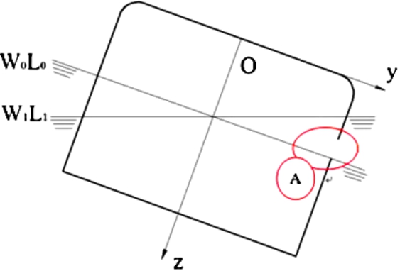
Figure 1 shows a longitudinal schematic diagram of a capsized ship. Figure 2 shows a transverse schematic diagram of a capsized ship. The rectangular coordinate system of the damaged ship was established. The origin O exists in the cross area of the base plane, the midship section, and the longitudinal mid-section. The axes’ directions are as follows:

The longitudinal diagram of damaged ship.
The transverse diagram of damaged ship.

The diagram of damaged compartment.
Figure 3 shows a flooded damaged compartment, which is not filled with water because of air. Water will flow into the damaged compartment when the ship starts to sink. For the sake of simplicity, it is assumed that the damaged compartment sinks vertically. Consequently, the area of free surface (S) in the compartment is constant. The initial distance between waterline of compartment and opening is
Bernoulli’s equation along a streamline between point 1 and point 2 is given by:
Where
We assume that:
Here k is the function of μ, S and A.
The flow velocity through the opening, solved from equation (1) and equation (2), is:
The instantaneous water height:
Where
The time derivative for the volume of water corresponds to the negation of the volumetric flow through the opening:
Equation (6) can be obtained from equation (3) and equation (5):
The initial condition is:
The volume of water in the compartment is increasing. This can be solved analytically:
When a time period t has elapsed, the water level has increased to
So, the discharge coefficient is obtained from equation (8) and equation (9):
The inflow quantity of the damaged compartment of the ith value is given by:
The total water quantity of the damaged compartments of the ith value can be obtained as follows:
Where
Thus, the total flooding quantity which can be solved during uprighting is as follows:
Here,
This part of the work in the paper ignores the variation of trim. Consequently, the position of the ship is represented by the heeling angle φ and the draft (Fig. 4). W is the vessel’s weight and the coordinates of the center of gravity are given by (
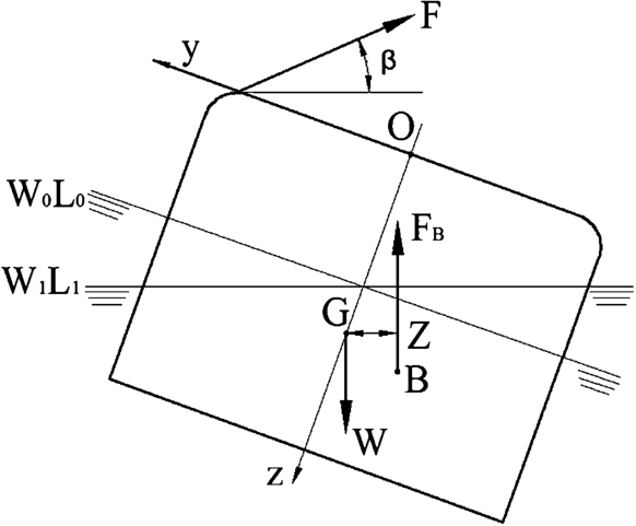
The force diagram of the uprighting process.
When the floating wreck is steady, the equilibrium of the weight-buoyancy is obtained:
Here, g is the acceleration of gravity and ∇ is the intact vessel’s volume.
Suppose that the righting force F acts on the capsized ship. It is a multi-stage process for righting a ship, and every stage is in a nearly stable state. The force equilibrium is obtained as follows:
Where β is the angle between the righting force and sea surface.
Where,
Where, (
Here,
The righting force formula can be obtained based on Equations (16) and (17):
Manual calculations, the table method, experiential formulae, and semi-empirical formulae are used to calculate the righting force in traditional marine salvage engineering. Manual calculations uses simple formulae to obtain approximate results. The table method sets project numbers, names, parameters, and costs in an excel table which is used to solve the stress of the hull. The results from the experiential formula must be revised in practice because they are not obtained based on exact mathematical derivations. The experiential formula can only provide a reference for calculation. The semi-empirical formula is obtained by theoretical derivation; the value range can be calculated as a practical reference. Traditional calculation methods have limited significance in salvage engineering because the process is slow and imprecise, and cannot determine the exact righting force [8]. The problems can be solved by using GHS software [14].
The GHS tools fall into two groups which are involved in performing a hydrostatic analysis. One tool corresponds to a tool for building a model of a vessel and the other is the tool used for analyzing the model. In phase one, the buoyant part of the hull must be defined in a suitable manner which satisfies the degree of precision. Internal subdivisions and tankage arrangements may be specified as well as non-buoyant superstructure for calculations. Phase two produces hydrostatic/stability evaluation data based on the model. This data may include tables and curves of hydrostatic properties, as well as stability and tank characteristics.
Establishment of the ship model
Simulation accuracy depends on the ship model quality. Some principles should be obeyed during the modeling process: twisted hull lines must be avoided to decrease computing errors; the changing active model area must be encrypted to improve solution precision; the line segment quantity in areas with little changes in model intensity should be controlled to expedite calculations. There are two methods for that can be used GHS software modeling: the interface operation and an editor program. This paper explores the editor program method.
The hull model must be established based on ship line plans. When creating a vessel model, the buoyant part of the hull must be defined in a manner suitable to the degree of necessary precision. The hull is divided into different sections. For common ships, the hull can be represented by 21 frames. However, for those ships with a complex surface, more frames are needed; the longitudinal coordinate of every section should be determined. The section consists of many points, which can be obtained by the transverse and vertical coordinates of points. Then, compartment models are built based on the compartment diagram. Here, compartment permeability and cargo loads can also be set.
Take Fig. 5 for example, where the origin O crosses the area of the base plane, the midship section, and the longitudinal mid-section, which is 8.6 m away from the bow. The axis direction is as follows:
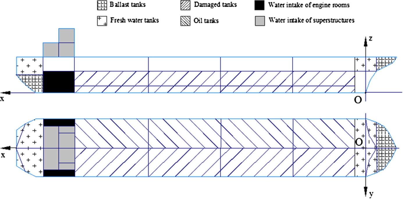
Hull and compartments.
The principal dimensions of the intact ship
According to the principal dimensions, loading condition and ship lines, the floatation and stability can be solved quickly by using GHS. Highly accurate results can be obtained by increasing the offset table values.
According to related literature and actual real salvages, some ships will still float on water even if some compartments are damaged. The ship lines, cargo and superstructure affect the uprighting process. Water flow, tide, and wind are also important factors to consider [2,24,26]. In traditional calculations for righting capsized wrecks, calculation results are often inaccurate because the equation only analyzes certain stages of the uprighting process [21,28]. The four uprighting processes were simulated using GHS software to study the factors that relate to uprighting:
Case A: The ship listed 169.15° to starboard, had a trim of
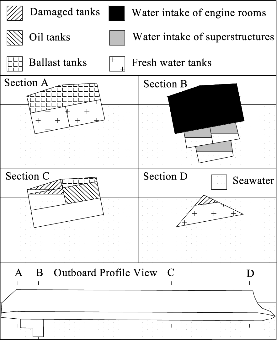
State of case A capsized ship.
Case B: The ship listed 166.33° to starboard, had a

State of case B capsized ship.
Case C: The ship listed 170.19° to starboard, had a 0.09° trim, and an origin draft of
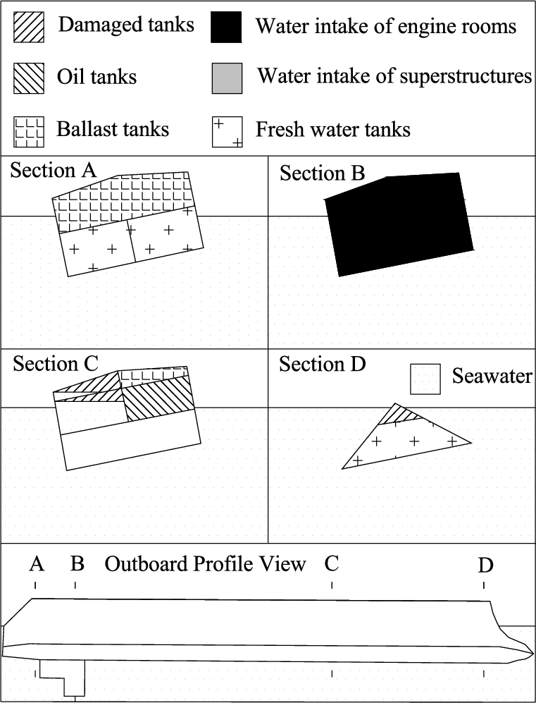
State of case C capsized ship.
Case D: The ship listed 169.39° to starboard, had a
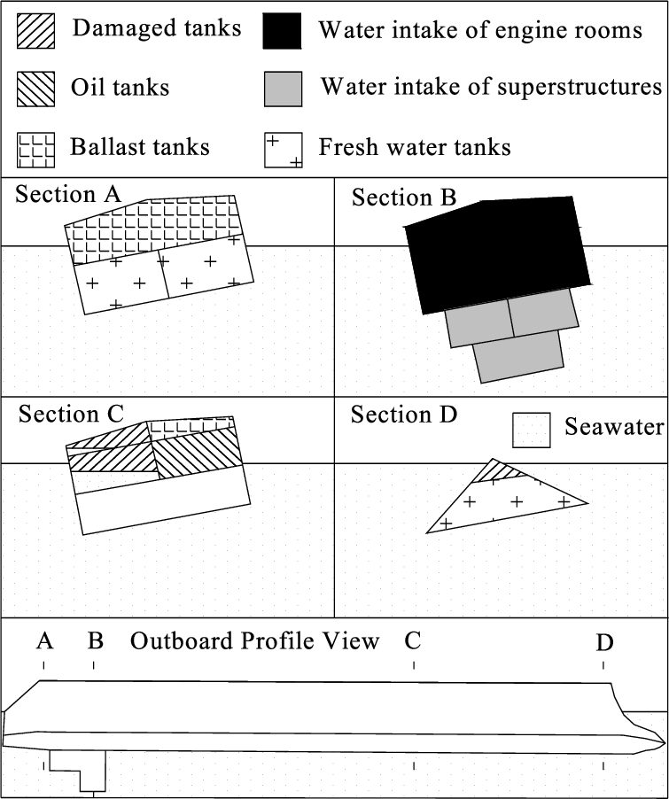
State of case D capsized ship.
Comparison of the righting force during uprighting
Static stability of the capsized ship determines the difficulty of uprighting (Fig. 10). Negative values of the curves represent the stability of the ship in upright conditions. Negative stability is helpful during the uprighting process, because the ship is prone to return to the neutral position without the righting force. Then a moment in the opposite direction is needed to maintain a steady speed, which prevents the ship from being damaged again or from capsizing again.
The proportion between the maximum righting moment and the maximum righting moment in the opposite direction was 0.459, 0.486, 0.424 and 0.346 for cases A, B, C and D, respectively. So a greater righting force moment in the opposite direction was needed. In later phases of the process, the righting force moment was needed to maintain the balance of the ship.
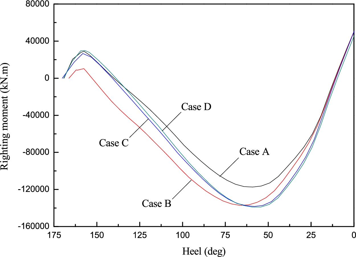
The static stability curves of capsized ships.
In the simulation, the righting force values of the four cases are given as follows: For case A it is 6000 KN, for case B it is 4800 KN, for case C it is 8000 KN, and for case D it is 8400 KN.
Comparison of trim during uprighting process
The trim angle of the hull changes during uprighting. Free water greatly intensifies this problem. Figure 11 shows the trim variation during uprighting, indicating positive trim for the stern, and negative trim for the bow. During uprighting, the changes of the trim angle for the four cases are 1.12°, 1.04°, 0.59° and 1.21°, respectively. This is relatively smaller than the heeling angle variation. For case C, the trim change was relatively small because the superstructure was detached.
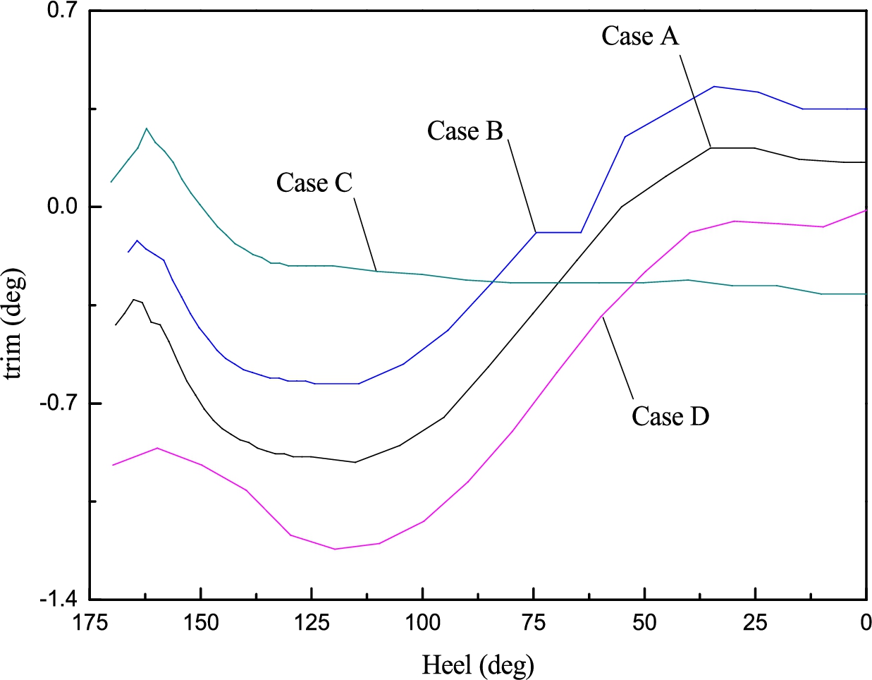
Trim variation during uprighting.
During uprighting, the flooding quantity of the damaged compartments changes with the heeling angle (Fig. 12). For the first three cases, the compartments’ openings are bigger. There is a large amount of water in the damaged compartments; the flooding quantity is less affected by the superstructure. For the fourth case, the compartments’ opening is small and there is a small amount of water in the damaged compartments because air cannot be released completely.

Variation of total flooding quantity of damaged compartments during uprighting.
Greater reserve buoyancy could ensure wreck insubmersibility. Because damaged compartments cannot be repaired, displacement changes when water is flow into and out of the damaged compartments during uprighting. Figure 13 represents the corresponding relation of displacement and original draft. Total displacement 1 represents the displacement of the enclosed space of the hull with superstructure, and total displacement 2 represents the displacement of the hull without superstructure. In light of the simulated data, the displacement of all cases did not exceed the permitted value during uprighting. The displacement variation tendency agrees with the origin draft for all cases. The damaged compartments were automatically drained of water during the beginning of the process. The quantity of flooding water increased quickly when the opening was beneath the water level.
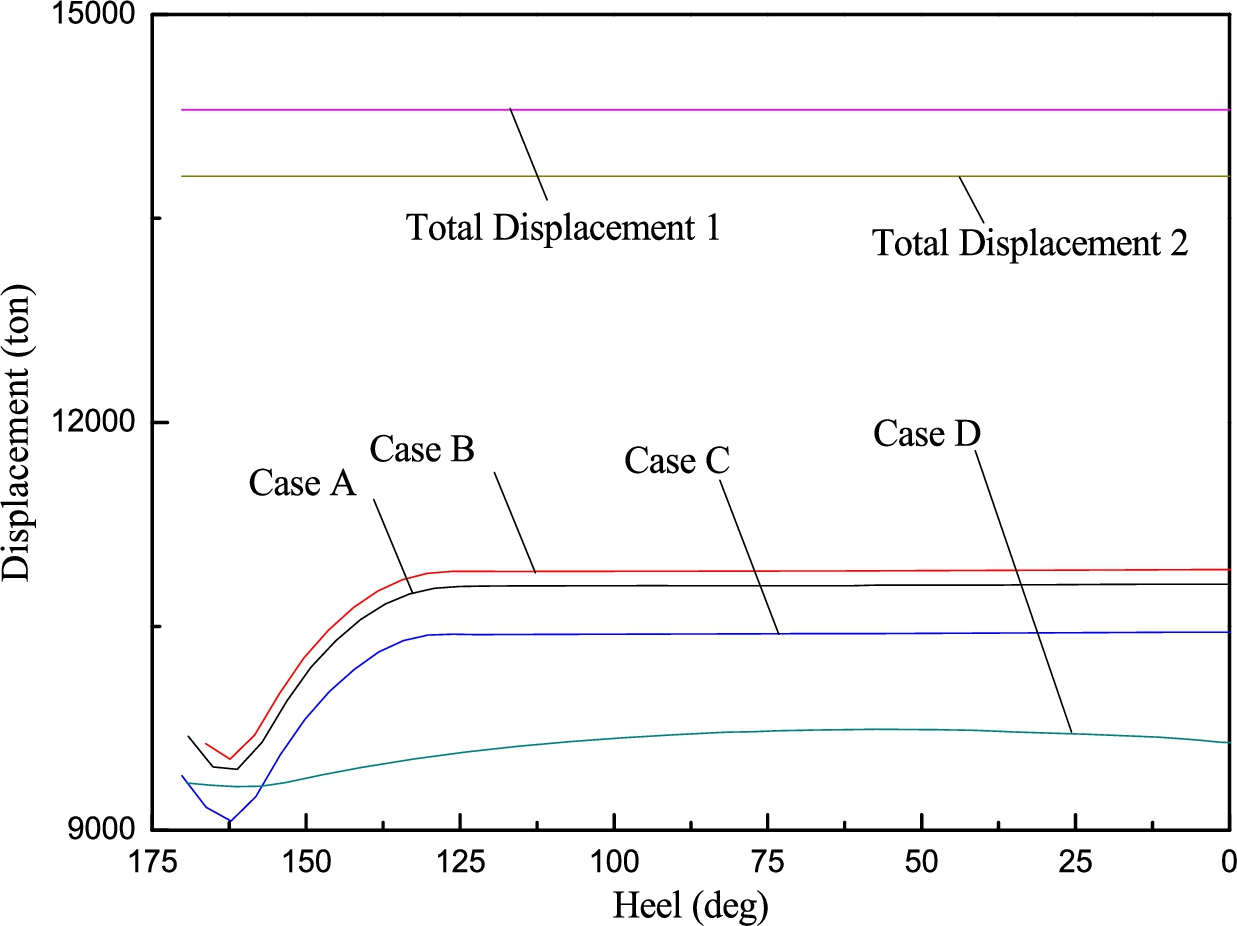
Displacement variation during uprighting.
The longitudinal load of hull exceeds the approved stress and this may bring about a serious accident. Thus, the strength analysis of hull is related to the success or failure of the salvage project.
Figure 14 presents the changes of the maximum shear force along the longitudinal direction for all cases. The maximum shear forces were all located at the same position, and the distance between the position and origin was 88.9 m, which was near the ship stern. The maximum shear force for the first two cases had the same change tendencies, which was relatively small. The first two had relatively a uniform loading in the hull. The superstructure of case C was detached, but the shear force rose obviously in the middle and latter part of the process. The load distribution in case D is different from the others due to the air cushion effect. The maximum shear force does not increase with flooding quantity or displacement.
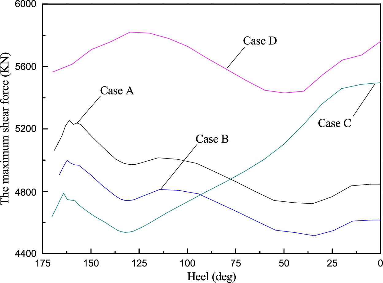
Variation of the maximum shear force during uprighting.
Salvaging damaged ships is a quite complex engineering task, especially when the damaged compartments cannot be repaired. The main work and results of this paper are as follows:
The uprighting process can be divided into numerous static states. In general, the flooding quantity of the damaged compartment which is not filled with water because of air is not easily obtained. According to the Bernoulli Equation, the flow velocity of the opening is obtained and the flow coefficient can be further deduced. At last, the righting force is solved by calculating the flooding quantity.
Four typical uprighting processes concerning capsized ships are simulated using General Hydrostatics software (GHS). The results show that the effect of flooding water distribution is more obvious than flooding quantity and displacement for a ship with many damaged compartments when the trim angle variation is very small. Take case C for example, where a higher shear force was developed without too much flooding water.
During the uprighting process, a righting force moment in the opposite direction is needed to maintain a steady speed, which prevents the ship from being damaged again or from capsizing again. The righting force moment in the opposite direction can be larger than the righting force moment in the positive direction. The proportion between the maximum righting moment and the maximum righting moment in the opposite direction was 0.459, 0.486, 0.424 and 0.346 for cases A, B, C and D, respectively.
Footnotes
Acknowledgements
The authors thank the anonymous reviewers for their valuable remarks and comments.
This paper is funded by the Fundamental Research Funds for the Central Universities (3132016354, 3132016069), the Key Technology and Demonstration of Helicoper Rescue Ability Promotion of Severe Sea Condition (2013328225080), and National Sci-Tech Support Plan (2014BAK05B06).