
Abstract
During the design process of an offshore vessel, the DP system is not representing one of the primary constraints for the general arrangement of the vessel. Usually the location of the thruster devices is driven by the internal spaces available, i.e. the thrusters position is not optimised to reach the maximum capability. This is also true for a conversion of an existing vessel. Nowadays almost all offshore vessels require the installation of a DP system on board, means that it could be worthy to study more in detail the arrangement of the thrusters in such a way to maximise the capability of the vessel to keep position with a determined amount of power installed on board. In the present work a procedure aimed to find an optimal thruster location on the hull during early design stage will be presented. Using a quasi-static approach for DP capability evaluation, an optimisation procedure based on genetic algorithm has been developed, considering the constraints given by the vessel geometry. The discussion is supported by a test case on a reference vessel, were the original layout is compared with two possible optimised configurations.
Introduction
The thruster’s locations of a Dynamic Positioning (DP) System are usually related to particular issues due to the internal subdivision of the offshore vessel where the device should be installed. In fact the general arrangement is studied to optimise the internal spaces needed to primary operations of the vessel [22], like the drilling area for a drill-ship or the pipe launching line for a Pipe-Lay Vessel (PLV). For converted ships the problem of thruster’s disposal is of secondary importance. Once a conversion of an existing vessel is investigated, the thruster location is coming from the free spaces resulting after the installation of the new equipments, often leading to asymmetric configurations [16]. Another issue is related to the size of the steerable devices [21]. Due to regulations given by Classification Society, the necessity to grant a particular Class notation for multiple failure cases [5,6] requires the installation of more power then that purely necessary for vessel operations.
In a preliminary design stage of a new built offshore vessel, once the final configuration of the thrusters is approximately known, it is convenient to perform dedicated DP calculations to roughly evaluate the current system capability. It is usual to represent the obtained results in form of DP capability plots [20], where the DP system performance is represented as the maximum sustainable wind speed at each encounter direction. In particular, it is possible to asses the real limiting environment for operations including also the DP capability [12], highlighting that the power installed on board is lower/higher than necessary. Because the number of devices installed on board cannot be reduced due to redundancy requirements, a dedicated study can be carried out to improve the total efficiency of the DP system. For this purpose a complete time domain simulation is not recommended due to its intrinsic complexity, while a quasi-static approach can give a sufficiently accurate capability estimation for preliminary design stage with a relatively short calculation time.
At present it is really difficult to find an analytical formulation for the DP capability as function of the thruster’s position and rated power. To this purpose, the area of the capability plot has been used to compare different design solutions, the best ones having the larger areas. Alternatively, other targets can be used by the designer according to his experience, as, for example, the case of the lowest maximum sustainable wind speed for all the calculated directions. Here, in order to maximise the capability plot area, an optimisation procedure based on genetic algorithms (GA) has been used and, for each generated thrusters configuration, a complete DP calculation has been carried out to determine the final area of the capability plot and thus rate the overall DP capability of the vessel.
As well known, the capability plot shape and area are strongly influenced by the thrust allocation algorithm used for the calculations [14], while the calculation complexity of the most powerful procedures [13], is not adaptable with the GA based optimisation procedure selected for thruster positioning. So less complicated thrust allocation approaches have to be used, at the preliminary design stage, to avoid too much computation effort, as for example a procedure based on pseudo-inverse matrix. In such a case, thruster-thruster interactions are not directly considered in the thrust allocation procedure, but those effects can be implicitly included by imposing a limiting distance between thrusters (e.g. 4 thruster diameters [7]). As a first step, the location of any single device can be optimised to improve the total capability of the vessel without changing the thruster sizing. Another step can be to change the thrusters size without changing their position or manage a combination of the previous two possibilities.
To better understand the impact of this procedure on the final design, the proposed method has been applied on a PLV vessel under conversion, highlighting the differences in terms of thruster configurations that can be obtained when adopting different strategies.
DP calculations
The core of quasi-static DP calculations is the thrust allocation process, which is carried out by solving the static equilibrium between external loads and thruster delivered forces. When considering a system composed by N thrusters, the equilibrium with respect to the pivot point O [3], is given by:
Experience shows that it is convenient to consider the components in x and y direction of delivered thrust instead of magnitude and direction of the thrust vectors. It follows that system (1) is linear, being then potentially easier to be solved in the classical matrix form
Thrust allocation
The adopted method is the one using the pseudo inverse matrix [23], where the selected mathematical process needed to evaluate
This kind of optimisation is really simple and straight forward, but it is subjected to some limitations as the solution does not ensure that all the thrusters reach at most their saturation level. In fact, solve equation (3) will not ensure that the thrusters satisfy the constraint given by the maximum available trust. Once the solution allocates more thrust than what is available on a thruster, it is possible that the other devices have still some additional thrust to deliver before reaching saturation. For this reason the actual procedure has been modified by implementing recursive calculation that allows to satisfy the initial constraints, respecting the maximum available thrust per each thruster.
Thrust determination
To satisfy the equilibrium system (2) it is necessary to evaluate the thruster’s delivered thrust at each condition. The amount of thrust needed to stationkeeping purposes is given by the thrust allocation algorithm, however this value should be compared with the maximum available thrust in the analysed condition. Usually the maximum available thrust is given for an undisturbed bollard pull condition. This value should be reduced according to multiple thrust reduction effects [10,17] that may occur during DP operations as: thruster-thruster, thruster-hull and thruster-current interactions.
This kind of reductions can be evaluated in multiple ways [4,8], according to the level of accuracy needed by the calculation. In the present study, since the evaluation of DP in early design stage is investigated, simple formulations have been considered to evaluate thruster-hull and thruster-current interaction effect, considering the indications given by ABS [1].
As mentioned, thruster-thruster interaction effects have been neglected from the thrust evaluation process in order to accelerate computation time adopting the pseudo-inverse matrix approach. This is the actual limit of the proposed procedure, that could lead to possible overestimations of the capability performances for particular thruster configurations. However, as first approximation, additional constraints can be added to the thruster position, in such a way to avoid closely spaced installations. In that case, the simplification on the thrust allocation becomes less significant in terms of reliability of the obtained result for an early design stage.
Environmental and external loads
To perform the DP calculations with equation (1), it is necessary to evaluate the quasi-static loads acting on the vessel, means the environmental and, in case, other external loads. Here, the environmental loads are given by wind, waves and current, together with the possible external loads given by mooring lines, raisers or connected pipes. In such a way the requested forces and moment can be rewritten as:
To face this kind of issue suitably it is possible to consider load coefficients in non-dimensional form, obtaining more flexibility when vessels of the same typology should be analysed. It means that if some measurements are available for a vessel, then it is possible to use them also for other similar ships as a first guess.
Before carrying out the DP calculations it is necessary to define which kind of environmental conditions have to be considered for preliminary capability calculations. In fact the environmental loads can be combined in several different ways, for example by changing the mutual directions or the relative contributions according to the guidelines of the classification rules [3,6]. Despite the guidelines are differing for some peculiarities regarding load coefficients, they almost agree with the fact that environmental loads should be considered concurrent, means coming from the same direction. This assumption has been considered in all the present calculations, together with a constant current velocity of 2.0 kn and a wind-wave correlation for the North Sea [20]. In such a way by increasing stepwise the wind speed it is possible to determine the maximum wind velocity that the DP system is able to face, taking automatically into account the changes in the corresponding wave loads.
Dynamic allowances
The nature of a quasi-steady DP calculation, lead to an overestimation of the final stationkeeping capability of a vessel in comparison with a time domain simulations [18]. To overcome this issue, in early design stage DP analysis dynamic allowances are used [19]. In such a way all the dynamic effects neglected by quasi-steady approach are taken into account, considering an addition to the environmental and external loads. In case time domain calculations have been carried out on the same or on a similar vessel, than a specific allowance can be evaluated [11], otherwise standard allowances can be used. In the present study, the dynamic allowances have been considered with an increase of the 25 % of the environmental and external load, as suggested by DNV-GL [7] for preliminary calculations.
Optimisation strategy
The purpose of the strategy is to obtain an optimal thruster disposition in order to increase the total DP capability of the vessel. To do that an optimisation procedure has been implemented to maximize the goal. The allocation procedure used to solve the station-keeping problem (1) requires by itself a dedicated optimisation strategy. For such a reason the complete problem to be solved refers to an optimisation process that should run multiple optimisations related to thrust allocation at each step.
The problem of optimal thruster position on the hull bottom in the sense of maximum DP capability is not easy to model because multiple sub-problems can rise up once different constraints are given. Through this study only the simple problem of location is considered, selecting to keep the thruster size as a constant. Limitations in terms of feasible positions can be set for each thruster or only for someones, letting the other positions free to change. Within the strategy, the thruster-thruster interaction effect can be implicitly avoided by assuming their minimum distance as a constraint. Questions can rise up for the optimal selection of thruster sizing and so on. Based on this kind of considerations more details can be added to the function that should be optimised as objective of the stated problem.
Objective function
Once the problem to solve has been defined, means the optimum location of thrusters with a fixed rated power, it is necessary to define what is the objective function to optimise within the assumed constraints. Since the capability of the DP system is considered a function of the maximum wind speed that the thrusters can face at each angle of environment, here the assumed function to optimise is the inner area of the capability plot, which is certainly representative of the overall capability of the DP system.
Because the unknowns of the problem are the
Genetic algorithm
A promising approach to solve the stated optimisation problem is based on genetic algorithms [9]. In fact, it deals with a problem where the objective (5) of the optimisation process is coming from a simulation in which the unknown positions are modifying the output but are not explicitly a part of the objective function. In fact the thruster locations
By using alternative optimisation techniques the problem would be the same, because locations are present only in the constraints definitions of the optimisation problem. For such a reason it is necessary to explore the possible changes of equation (5) inside the feasible thruster location space on the vessel.
GA can be suitably used to find the solution inside the design space, trying to search an optimal value for the selected objective. Being heuristic adaptive search algorithms, the GA are based on the evolutionary ideas of selection and genetics. So they represent a suitable exploitation of a random search aimed to solve constrained or unconstrained optimisation problems. Even though the process is based on a randomised generation procedure, the algorithm itself is not random at all, using the history of consecutive generations to direct the search into the optimal values region inside the search space. Once the space search is consistently wide or the search is involving multi-modal state space or n-dimensional surfaces, then a genetic algorithm can provide more benefits than conventional optimisation techniques [15].
The procedure starts with the generation of a feasible population, to do that firstly the longitudinal thruster coordinates
After the determination of the initial population, all the individuals are evaluated according to the objective function given by equation (5) and the reproduction procedure can start. During the first iteration, the offsprings are generated in order to maintain the best individuals. From the second iteration and next, the generation step is substituted by the crossover an mutation procedure. The evolution procedure can be summarized in the scheme presented on Fig. 1, where the main processes provided at each generation step are schematically shown.
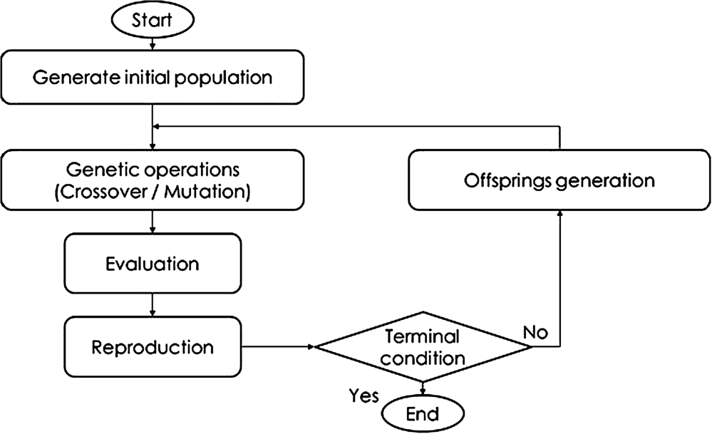
Evolution scheme of a GA for optimum solution search.
In particular the crossover procedure has been implemented according to an exponential scheme, considering two crossover probability factors that are used to combine the chromosomes of four different distinct individuals. The children resulting from crossover and mutation are then compared according to objective function (5). In case that function value is higher than the one of respective parents, then the individuals will replace the parents in the next generation. This kind of process is repeated until a suitable final value for the objective function is reached.
The simulation study has been carried out on the Pipe Lay Vessel (PLV) shown in Fig. 2. This vessel has been selected because it presents a particular non-symmetrical thruster disposition and has been designed with thrusters of different size. The vessel is equipped with a total of 7 thruster devices, 6 azimuthal thrusters and a fixed bow tunnel thruster. As assumption, only the 6 steerable devices are used during DP operation while the tunnel thruster is not considered in the calculations. Environmental loads are available for wind, waves and current.
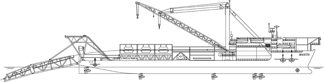
Profile view of the PLV vessel under analysis.
Geometric characteristics of PLV vessel
The main geometric characteristics of the PLV vessel are summarized in Table 1. Due to general arrangement constraints, the thrusters are located in an unusual way, partly non-symmetric (see Table 2 and case TS-00 in Fig. 9). Thrusters 2–5 are on the flat of bottom, while 6 and 7 are at the stern on the inclined buttocks and are used also for propulsion. The fore group of steerable devices consists of two closely spaced thrusters at different longitudinal positions, having a spacing higher than four diameters. Instead of a standard division in stern and fore thrusters, two thrusters are located more close to midship at different longitudinal positions and on the opposite sides of the ship (thruster 5 on starboard side and thruster 4 on port side). In such a way the thruster location is non-symmetric with respect to longitudinal axis. The only couple of symmetric thrusters with respect to the longitudinal direction are the two stern thrusters, mainly because they are used also for standard propulsive duties of the vessel and not for DP purposes only.
It must be noted that also the size of the thrusters is different, not in terms of dimensions (propeller diameter is fixed) but in terms of power. In fact the thrusters located close to midship have a lower available power with respect to the others.
Thruster and pipe location and main characteristics for case TS-00
Thruster and pipe location and main characteristics for case TS-00
The vessel has been designed for S-lay operations with a stinger mounted in non-symmetric position. To properly take into account the pipe-lay operation in DP calculations, a fixed external load due to pipe tension has been considered, acting on the vessel with coordinates and magnitude given in Table 2. Data are available for the environmental loads from dedicated experiments on model scale for the selected S-lay operational mode, granting a sufficiently accurate estimate of vessel’s DP capability.
The search of optimal location ensuring the maximum capability for the vessel has been divided in two different cases in agreement with the fact that the two back thrusters 6 and 7 are not dedicated exclusively to the dynamic positioning, but are also used to ensure the propulsion during transit. Therefore, see Fig. 2, the two stern thrusters are not located on the flat of bottom of the vessel, but are integrated with the stern buttocks like in any propulsive configuration.
For such a reason, considering the retractile thrusters installed on the flat of bottom, according to the designers request it has been decided to keep fixed the position of propulsive thrusters in both the tested hypotheses. In the first case (TS-01), the remaining four thrusters are moved during the optimisation process while in the second case (TS-02), a completely independent DP system is supposed to be mounted on the vessel by considering the propulsion system independent from the DP.
First case (case TS-01)
In the first case TS-01 we examine a vessel with the same thruster configuration of the original vessel, considering two propulsive thrusters
With these preliminary considerations, the total amount of unknowns is 8, being representative of two spatial coordinates of four thrusters on the flat of bottom. To ensure that the thrusters will be located on the flat of bottom, each time that a thruster is located in a determined longitudinal position, the transverse bounds are automatically updated according to the available outreach.

Genetic algorithm convergence diagram for case TS-01.
Having 8 unknowns, each population is composed by 64 individuals. Due to the complexity of the objective function, it is not granted that the function values of the best individual will change at each iteration, for such a reason, the exit point of the algorithm is set to a predetermined number of iteration runs, keeping as optimum the final value of the objective function. After several tests it has been found that 5000 consecutive iterations are ensuring convergence for the algorithm. The algorithm convergence diagram for the specific case is shown in Fig. 3, highlighting that a total increase of objective function of about 9% has been found during the optimisation process (see Fig. 4). The final obtained thruster configuration is presented in Fig. 9 and Table 3 in graphical and tabular form. In this case, the fore thrusters 2 and 3 maintain a relative spacing of the four diameters, without the need to consider the additional constraints as per equation 8.

DP capability plot comparison between cases TS-00 and TS-01, resulting from optimisation procedure.
Power and optimal thruster positions TS-01, TS-02 and TS-02*
The second analysed case TS-02 refers to a new idealised configuration, where a dedicated DP system is assumed for the vessel, considering the installation of a set of 6 retractile thrusters on the flat of bottom (2–5, 8 and 9). The total installed power is then comparable with the previous configuration, because the thrusters 6 and 7 are used for propulsion only, so they are switched-off during DP operations. The constraints on the transverse position of each thruster are automatically implemented as function of longitudinal position, according to the flat of bottom geometry.
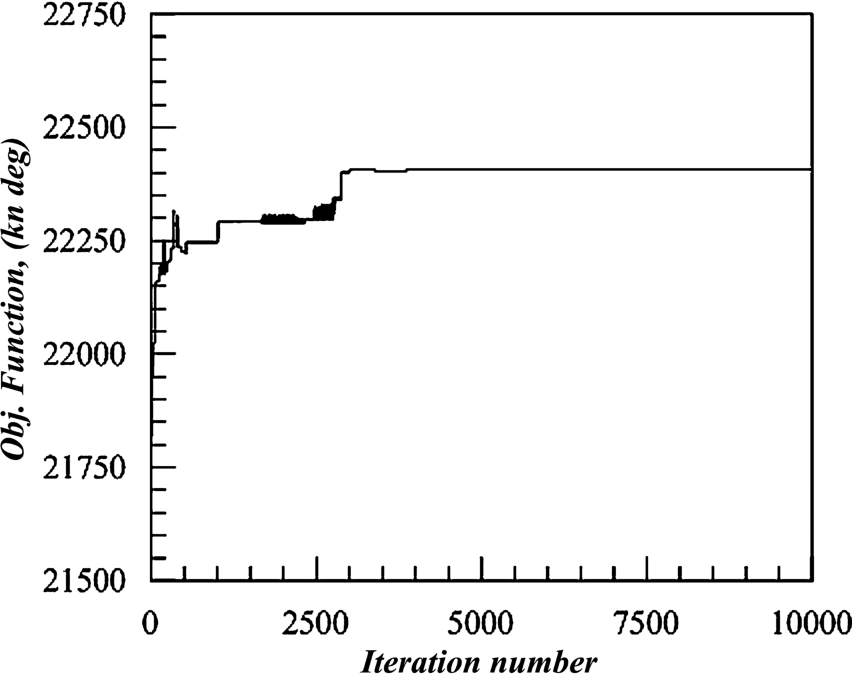
For this case, the total number of unknowns is 12, so each population is composed by 96 individuals. As for the previous tested case a set of trial rounds has been carried out to find the necessary iteration number to reach convergence. Having increased the unknowns, for the specific case a total number of 10000 iterations has been considered for the genetic algorithm procedure. The specific convergence diagram for this case is reported in Fig. 5, the optimising process led to a capability increase of about 6% in objective function (see Fig. 6) by adopting a configuration as per Fig. 9. However, as it can be observed in Fig. 9, the thrusters are located in two distinct groups, one in the fore-ship and one in the aft, being too close to each other. This is due to the simplifications used on the allocation algorithm, that is not considering the presence of thruster-thruster interaction effects and forbidden zones. For such a reason, it has been selected to study another case, imposing position constraints between the thrusters according to equation (8), in order to avoid finally not reliable solutions.

Genetic algorithm convergence diagram for case TS-02.
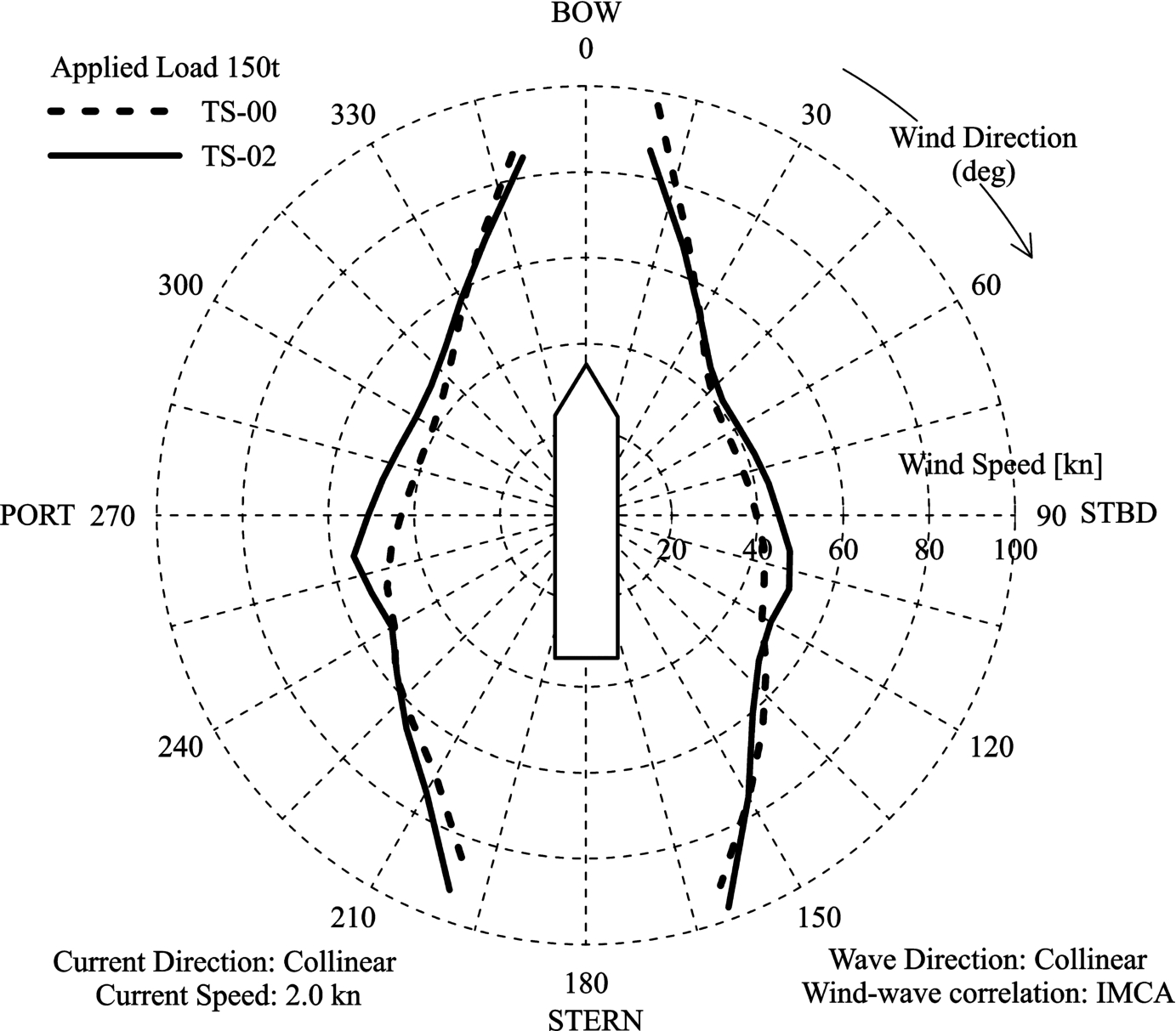
DP capability plot comparison between cases TS-00 and TS-02, resulting from optimisation procedure.
Case TS-02* refers to the same configuration as TS-02, considering the installation set of 6 retractile thrusters on the flat of bottom (2–5, 8 and 9), having the same size as the previous case. In addition to the transverse position constraints according to bottom geometry, additional constraints have been imposed per each thruster, imposing that the thruster centre of rotation should be distant more than 4 propeller diameters to all the other thrusters. This kind of constraint has been selected to overcome to the thruster allocation algorithm simplifications, neglecting thruster-thruster interactions and forbidden zones. In fact, it is usually considered that thruster interaction effects drastically decrease when thrusters are located at a distance higher than about 4 diameters [7].
Also in this case, having 12 unknowns and populations composed by 96 individuals, 10000 iterations have been considered for the genetic algorithm procedure. The convergence diagram is reported in Fig. 7, having a lower capability than the case TS-02 (see Fig. 8), but still increasing the objective function value of about 3.5% compared to original configuration. The final thruster layout can bee seen in Fig. 9 and Table 3, showing that the fore and aft groups are spaced according to the selected constraints.
Genetic algorithm convergence diagram for case TS-02*.

DP capability plot comparison between cases TS-00, TS-02 and TS-02* resulting from optimisation procedure.

Thruster positions for cases TS-00, and optimal thruster positions TS-01 and TS-02.
By comparing the solutions obtained from the examined cases, several considerations can be draw out. As first, the first solution TS-01 is giving a higher DP capability compared to the original thruster configuration. That means the original thruster configuration was not the best possible choice for the selected vessel. Also the second option, represented by case TS-02 is giving a higher capability area compared to the original one, however the solution was not feasible, since the thruster are resulting too close to each other. Considering the additional constraint to avoid interaction on the thruster mutual location (case TS-02*) the capability area is still higher than the original one.
Comparing the first two optimised solutions TS-01 and TS-02, it can be highlighted that condition TS-02, the one with equal thrusters, is increasing the capability of the vessel for beam seas conditions (Fig. 6), without losing a lot of area for head seas while condition TS-01, the one obtained by changing only 4 thrusters, is gaining area for stern and stern quartering directions (Fig. 4). However, while considering the feasible solution TS-02*, the capability increase in the side area is lower (Fig. 8) as expected due to interactions; this is mainly due to the fact that the thrusters are no more closely grouped in the fore and aft part of the flat of bottom.
Finally comparing the solution TS-01 with TS-02*, it can be stated that, for the analysed vessel, the configuration with the two main propulsive thruster adopted for DP is more favourable than the one with 6 thruster mounted on the flat of bottom.
Conclusions
The presented procedure for the optimal thruster disposal on an offshore vessel is giving the possibility to find thruster configurations that can improve the total DP capability of the vessel. An improvement with respect to the original thruster disposal has been found for both two tested configuration, with a capability increase of about 9% in the first case and 6% in the second one in term of DP plot area. Since the second case was not feasible, due to the close proximity of the thrusters, additional constraints have been added, determining a feasible solution that is still 3.5% better than the original one.
Due to the high number of calculations needed to determine the thruster location objective function a simple thrust allocation algorithm has been used to obtain the capability of each generated individual. By doing that, the number of calls to the thrust allocation function is reduced with respect to more complex allocation algorithms, decreasing the time needed to evaluate a capability plot for each individual. With the current settings, the calculation of a single capability plot requires about 0.2 seconds, by using a more complex thrust allocation the time is increasing up to more than 1 second. On a single calculation this is not appreciable, but once as per case TS-02, about 10000 iterative generation are needed to ensure convergence the total calculation time will increase from 1.5 days to about one week. A more complex thrust allocation will increase the reliability of the final result, however, it will increase also the calculation time.
To decrease the calculation time, the thruster location objective function can be studied fo the most representative environmental condition. This allows the investigation of a configuration with minimal fuel consumption resulting from a more advanced thruster allocation strategy. The procedure as it is here presented, being capable to work with multiple thruster position constraints, could be also used to study a combined optimisation between thruster position and general arrangement of the vessel. This will give to the designer the possibility to evaluate different solution in a recursive way.
Conflict of interest
None to report.